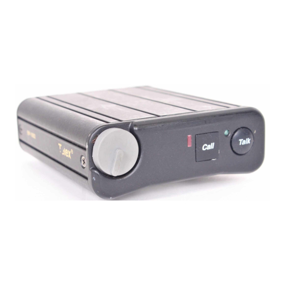
Telex BP-1002 Operating Instructions Manual
Belt packs
audiocom intercom system
Hide thumbs
Also See for BP-1002:
- Operating instructions manual (24 pages) ,
- Operating instructions manual (10 pages) ,
- Operating instructions manual (20 pages)
Summary of Contents for Telex BP-1002
- Page 1 Telex Operating Instructions BP-1002/BP-2002 Belt Packs ® Audiocom Intercom System 93507740-000 Rev G 05/2005...
-
Page 3: Fcc Statement
INTRODUCTION The Audiocom® BP-1002 and BP-2002 are microprocessor controlled one- and two-channel intercom belt packs. An internal switch and jumper setting allows the units to be used with Clear-Com ® components, if desired. Other internal switch and jumper settings allow the unit to be uniquely configured to the operator’s requirements. - Page 4 Software IMPORTANT - Please read this document carefully before using this product. THIS DOCUMENT STATES THE TERMS AND CONDITIONS UPON WHICH TELEX COMMUNI- CATIONS, INC. (the ‘COMPANY’) OFFERS TO LICENSE THE INSTALLED SOFTWARE OR PRO- GRAM (the ‘SOFTWARE’) FOR USE WITH THE PRODUCT IN WHICH IT WAS INSTALLED. YOU ARE AGREEING TO BECOME BOUND BY THE TERMS OF THIS AGREEMENT.
-
Page 5: Operation
• Via the local-power (pin 2) of the intercom channel connector The BP-1002 belt pack receives power externally, via the intercom channel. Both the BP-1002 and BP-2002 will pass system power through to subsequent belt packs that are “daisy chained” together. - Page 6 Then, use a small flat-blade screwdriver to increase or decrease your voice level while talking into themicrophone. (This control is accessible by removing one screw of belt clip.) 6. H : This connector accepts a four-wire Telex® boom-microphone headset. EADSET ONNECTOR 7.
-
Page 7: Operating Modes
The BP-2002 belt pack may also be powered from an optional power supply (18-30 VDC) connected between pin 2 (+) and pin 1 (-) of the intercom channel connector. 8. I : On the BP-1002, the intercom channel is connected via a pair of 3-pin NTERCOM HANNEL ONNECTORS connectors (one male and one female). -
Page 8: Internal Switches, Jumpers And Adjustments
INTERNAL SWITCHES, JUMPERS AND ADJUSTMENTS There are several internal switches, jumpers and an adjustment that affect operation. These are described below. To gain access to the switches, jumpers and the adjustment, disconnect all power and line connections. Remove two screws from the top of each side and two screws from bottom of each side. - Page 9 NOTE: On the BP-1002, jumper JP6 must always have pins 2 and 3 shorted. Side Tone Adjustment (R145) The side tone adjustment is accessible either internally (refer to Figure 2) or by removing the belt clip mounting screw (callout 5 in Figure 1).
- Page 10 c t i c t i & : c i & : c i & & & & & & & & & ® ® ® & l l a , y l ® & , e l l l a , y l ®...
-
Page 11: Connector Pin Configurations
Pin 2 Headset microphone high Pin 3 Headphone high Pin 4 Headphone low Intercom Channel Connectors BP-1002 Type: One XLR-3M and XLR-3F pair (callout 8 in Figure 1) ® Audiocom Mode (Internal switch SW1 and jumpers JP4, JP5, JP2 and JP1 set to BAL position) -
Page 12: Specifications General
SPECIFICATIONS GENERAL: Power Requirements: Channel supplied: 24 VDC nominal, 45 to 70 mA Local-power: (BP-2000 only) 24 VDC nominal (18 to 30 VDC), 45 to 70 mA Environmental Requirements: Storage: -20ºC to 80ºC; 0% to 95% humidity, non-condensing Operating: -15ºC to 60ºC; 0% to 95% humidity, non-condensing Dimensions: 5.0"... -
Page 13: Headphone Amplifier
Unbalanced Intercom Channel: Output Level: 480 mVrms ±10% Input Impedance: 200 ohm ±5% Bridging Impedance: greater than 10,000 ohm Call Signalling: Send: 12 ±3 VDC Receive: 4 VDC minimum HEADPHONE AMPLIFIER: Voltage Gain: 20 ±3 dB from the line Maximum Output: 60 mW into 150 ohm Frequency Response: 200 Hz to 8 kHz with no more than 4 dB deviation... - Page 14 Figure 4. Board Number 9040-7740-000. : y l : y l Default Settings...
- Page 15 TO PREVENT DAMAGE TO THE EQUIPMENT, THESE MODIFICATIONS SHOULD ONLY BE MADE BY QUALIFIED TECHNICIANS. If desired, the Mic-Kill and Call signal features can be disabled in the BP-2002/BP-1002 by remov- ing a surface-mounted capacitor from the printed circuit board. Perform the following: 1.
- Page 16 Figure 3. Printed Circuit Board...
-
Page 17: Factory Service
ARRANTY EPAIRS for warranty repair must be sent prepaid and will be returned prepaid. - Equipment that is not under warranty must be sent prepaid to Telex. If ARRANTY EPAIRS requested, an estimate of repair costs will be issued prior to service. Once your approval for repair, and repair of equipment is completed, the equipment will be returned on a collect basis.


Need help?
Do you have a question about the BP-1002 and is the answer not in the manual?
Questions and answers