Table of Contents
Advertisement
Advertisement
Table of Contents

Summary of Contents for Asiatelco U270V
-
Page 1: User Manual
User Manual Gateway U270V... -
Page 2: Important Notice
Important Notice Due to the nature of wireless communications, transmission and reception of data can never be guaranteed. Data may be delayed, corrupted (i.e., have errors) or be totally lost. Although significant delays or losses of data are rare when wireless devices such as the router are used in a normal manner with a well-constructed network, the router should not be used in situations where failure to transmit or receive data could result indamage of any kind to the user or any other party, including but not limited to personal injury, death or loss of property. -
Page 3: Table Of Contents
TABLE OF CONTENTS Introduction ..................5 Product Overview ................5 Using your Router ................6 3.1 Package Contents ..................6 3.2 Router Interfaces ..................6 3.3 LED ......................6 3.4 RJ-45 Switch ....................7 3.5 Other Features ..................... 7 3.6 Setting up your hardware ................8 Configuring your Router .............. - Page 4 Technical Specification ............... 40 Certification ..................41...
-
Page 5: Introduction
In minutes, you will be able to connect your computers to the Internet and you will be able to make a phone call using VoIP. The following is a list of features that make your new U270V router an ideal solution for your home or small office network. Implementation of these features depends on the particular service provider and account features you have chosen. -
Page 6: Using Your Router
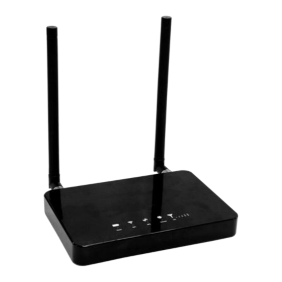
3.2 Router Interfaces The U270V is designed to be placed on a desktop or wall mounted. All the ports at the back of the router are for better organization and utility. The LED indicators are easily visible on the top of the router to provide you with information about network activity and status 3.3 LED... -
Page 7: Switch
Power On(Yellow) Only charger plug or Full charged Blinking(Yellow) Charger plug in and charge for battery Blinking (Red) Battery in and no charger plug in the battery is in low status, WIFI On(Yellow) WIFI has turned on Blinking(Yellow) Active data passed through Wi-Fi WIFI has turned off Blinking(Yellow) WPS is activated. -
Page 8: Setting Up Your Hardware
3.6 Setting up your hardware Make sure your router is not connected to any power source and that all the LEDs are OFF. How to setup the antennas for maximized performance: ① Antennas are located on both sides of the router. ②... -
Page 9: Configuring Your Router
a suitable network the Connect LED is lit yellow. Refer to the Signal LED’s for acquired signal strength and band. Locate the Ethernet cable that is included with your router. Plug one end of the cable into any Ethernet port on your router. Plug the other end of the cable into the networking port on your computer. -
Page 10: Status
Figure 4-2-1Dashboard Page 4.3 Status In this section you will find the status pages for Wi-Fi & LAN, 4G, Software versions, Device List, UPnP and VoIP. Figure 4-3-1 Status 4.3.1 WAN Status On the WAN Status page you can see WAN IP Address, WAN Primary DNS and WAN Secondary DNS information... -
Page 11: Wifi Lan Status
Figure4-3-1-1 WAN Status 4.3.2 WiFi & LAN Status On this page you can see Wi-Fi & LAN information such as SSID, Channel, Security mode, LAN IP and DHCP Server information. Figure 4-3-2-1 WiFi LAN Status 4.3.3 4G Status In the 4G Status menu you can see LTE information like Connection Status, SIM Status, SIM numbers, Radio levels, MIMO status and frequency of the LTE network you are connected to. -
Page 12: 4Software Status
4.3.4 Software Status On this page you can see installed IDU- and LTE software versions. Figure 4-3-4-1 Software 4.3.5 Device List In the device list you can see information regarding currently connected devices like hostname, MAC address, IP address, expiring time and connection type. -
Page 13: Settings
4.4 Settings The Settings section consists of three main menus named Basic Settings, Advanced Settings and System Settings. Figure4-4-1 Settings 4.4.1 Basic Settings Figure4-4-1-1 Basic Settings 4.4.1.1 LAN Settings On the LAN Settings page all settings for the internal LAN can be viewed and changed. -
Page 14: Subnet Mask
Figure 4-4-1-1-1 LAN Settings IP Address Enter the IP address of your router (factory default: 192.168.0.1). Subnet Mask Subnet mask is an address code that determines the size of a network. The subnet mask is by default set to 255.255.255.0 (/24) and cannot be changed. ... - Page 15 Specifies the amount of time in seconds a host will keep the assigned IP address. When the lease time is up the host will be assigned a new IP address. Static IP IP/MAC binding function, the router will assign a static IP address to a host with a MAC address matching with what is specified.
- Page 16 Figure 4-4-1-2-2 WiFi standard Network Name (SSID) To identify your wireless network, a network name called SSID (Service Set Identifier) is used. You can set it to anything you like and you should make sure that your SSID is unique if there are other wireless networks operating in your area.
- Page 17 WPA-PSK/WPA2-PSK a) WEP Security Mode Security Mode: OPEN, SHARED Key Format: Hexadecimal and ASCII formats are provided. Hexadecimal format stands for any combination of hexadecimal digits (0-9, a-f, A-F) in the specified length. ASCII format stands for any combination of keyboard characters in the specified length.
- Page 18 Figure 4-4-1-2-6 Default WiFi Security Figure 4-4-1-2-7 WPA-PSK Figure 4-4-1-2-8 WPA-PSK/WPA2-PSK 4.4.1.3 Multiple SSID On this page you can add multiple SSID’s to be used when connecting to your WLAN. New SSID’s will be displayed in the rule table and can be edited or deleted. Maximum rule count is 5.
- Page 19 Figure 3-4-1-3-2 Add New Rule Figure 4-4-1-3-3 Rule Table 4.4.1.4 WPS Settings On this page, you can modify WPS settings. This feature can make your wireless client within a few minutes automatically synchronized with the WLAN and establish the connection via Wi-Fi. ...
- Page 20 your WLAN. Enter the PIN of client device (1) Wireless clients choose enrollee mode, the wireless client software will randomly generate a PIN code. Then click on the tool interface "PIN" button. (2) Input the PIN code which got from the wireless client and click the “Apply” button on this “WPS”...
-
Page 21: 2Advanced Settings
4.4.2 Advanced Settings Figure 4-4-2-1Advanced Settings 4.4.2.1 MAC Filtering MAC filtering is a security tool that allows you to configure internet restrictions for specified devices based on MAC address. MAC filtering is disabled by default so it must be enabled before filters can be configured. If you choose the “Allowed”... - Page 22 Figure4-4-2-1-3 Add Rule Figure4-4-2-1-4 Rule Table 4.4.2.2 IP/Port Filtering IP/Port filtering is a security tool that allows you to configure internet restrictions for specified devices based on IP addresses and port number(s). IP/Port filtering is disabled by default so it must be enabled before filters can be configured.
- Page 23 Figure4-4-2-2-2 Enable IP/Port Filtering function Dest IP Address Enter the IP address of the IP packet destination. Source IP Address Enter the IP address of the IP packet source. Protocol Define what protocol to be filtered. Dest Port Range Define port numbers to be filtered (port 80 is for http).
-
Page 24: Content Filtering
Figure 4-4-2-2-4 Rule Table 4.4.2.3 Content Filtering On this page you can configure content filtering and the content filtering schedule. Content Filtering Content filtering blocks all traffic to and from web browsers containing words or URL’s specified in the rules. Figure 4-4-2-3-1 Content Filtering page Figure 4-4-2-3-2 Add New Rule ... -
Page 25: Port Forwarding
Figure 4-4-2-3-3 Configure Filtering Schedule Figure 4-4-2-3-4 Content Filtering Rules 4.4.2.4 Port Forwarding By opening ports in your router traffic from the internet can be routed to a specific device and application in your LAN. This is often used by servers or devices that needs remote management Figure 3-4-2-4-1 Port Forwarding page... -
Page 26: Virtual Server
Figure 4-4-2-4-2 Port Forwarding Setting IP Address Enter the IP address of the device in your LAN. Port Range Enter a fixed port number or a range of ports to be opened. This value has to match the application running on the local device (web servers often use port 80). -
Page 27: Vpn Passthrough
Figure 4-4-2-5-2 Virtual Server Setting IP Address Enter the IP address of the local device. Public Port Enter the port number to be used on the WAN side. Private Port Enter the port number to be used on the LAN side. Protocol ... -
Page 28: Demilitarized Zone
Figure 4-4-2-6-1 VPN Passthrough Note: VPN Passthrough does not mean the router can create VPN endpoints. VPN pass through is a feature that allows VPN traffic created by other endpoints to "pass through" the router. 4.4.2.7 Demilitarized Zone On this page you can configure a De-militarized Zone (DMZ) to separate internal network and Internet. - Page 29 Figure 4-4-2-8-1 Dynamic DNS setting 4.4.2.9 Routing On this page you can add new static routes to the routing table of the router. Figure4-4-2-9-1 Rule Table Figure 4-4-2-9-2 Configure the static routing settings Destination Enter the address of the network or host to be reached from the router. ...
-
Page 30: Wireless Clients
Interface Define if the gateway is on the LAN or WAN side. RIP When RIP is enabled the router will learn new routes from nearby devices. Figure 4-4-2-9-3 New rule table 4.4.2.10 Wireless Clients On this page you can see the detailed information about connected wireless devices, such as IP address, MAC address, MCS and RSSI. - Page 31 Figure 4-4-2-10-2 Kicked Wireless Stations 4.4.2.11 IP Whitelist On this page you can activate IP Whitelist. When IP whitelist is active internet traffic is only permitted to devices specified in the whitelist. Figure 4-4-2-11-1 IP Whitelist page Figure 4-4-2-11-2Enable IP whitelist function Figure 4-4-2-11-3Add new rule Figure 4-4-2-11-4 Rule Table...
-
Page 32: 3System Settings
4.4.2.12 Bridge Mode On this page you can enable bridge mode. By enabling bridge mode your WAN IP address will passed to the first device connected to the router with an Ethernet cable. Figure 4-4-2-12-1 LTE Bridge Setting page Figure 4-4-2-12-2Enable bridge mode 4.4.3 System Settings Figure 4-4-3-1 System Settings 4.4.3.1 Firmware Upgrade... - Page 33 Figure 4-4-3-1-1 Firmware Upgrade Remote Upgrade The remote upgrade feature will automatically scan a dedicated server for available firmware upgrades. If the device is running on battery the upgrade will be blocked if battery levels are 20% or lower. This feature can be disabled. Figure 4-4-3-1-2Remote Upgrade ...
- Page 34 external attacks. Figure 4-4-3-2-2System Security Settings page Remote management(via WAN) Enables or disables the possibility to access the web interface over the internet. Remote management(via Wi-Fi) Enables or disables the possibility to access the web interface over WiFI ...
- Page 35 On this page you can back up your custom configurations and store them locally in your device. The configurations-file can be used to restore your personal settings if lost or to add them on another U270V router. Figure 4-4-3-6-1 Backup & Restore 4.4.3.7 Watchdog...
-
Page 36: System Log
in order to rule out the router as the root cause of the failure. Figure 4-4-3-7-1 Ping Watchdog page Figure 4-4-3-7-2 Enable Ping Watchdog URL or IP address to ping Define what URL or IP to ping. Number of ICMP Request per ping group Define the number of ICMP requests to be sent for every ping. -
Page 37: 1Apn Settings
changes, reboots and if any firmware upgrades have been made. Figure 4-4-3-8-1 System Log page 4.5 4G The 4G section has two submenus, APN settings and PIN Management. Figure 4-5-1 4G 4.5.1 APN Settings On this page you can configure the router to connect to a custom APN. Faulty configurations will make internet connection unavailable. -
Page 38: Pin Management
Figure 4-5-1-1 LTE APN page 4.5.2 PIN Management On this Page you can enable or disable the use of PIN lock. Your PIN code can be found on the back of the SIM card shipped in the router package and you will be prompted to enter it on boot. -
Page 39: Voip Call Function
Figure 4-5-2-3 PUK Management page 5 VoIP Call Function Note Your router’s LTE and VoIP accounts must be properly activated for VoIP call functions to work. To setup your wired, landline phone for VoIP calling, plug the phone’s RJ-11 cable into the “TEL” port on your router as shown below. Consequently, you must first disconnect the phone from the fixed phone line, and connect it to the router instead. -
Page 40: Activating Voice Over Ip
5.1 Activating Voice over IP In order to use Voice over IP you must have an account with Net1. If you do not have the service pleasecontact Customer Service. 5.2 Placing Voice Calls 1. Turn on the router. 2. Lift the handset from your phone. 3. - Page 41 7 Certification...
Need help?
Do you have a question about the U270V and is the answer not in the manual?
Questions and answers