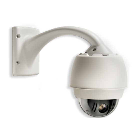
Bosch VG4 Series Installation Manual
Autodome modular camera system
Hide thumbs
Also See for VG4 Series:
- Installation manual (108 pages) ,
- Firmware update manual (42 pages) ,
- Manual (36 pages)
Table of Contents
Advertisement
Advertisement
Table of Contents

Related Manuals for Bosch VG4 Series


Summary of Contents for Bosch VG4 Series
- Page 1 AutoDome Modular Camera System VG4 Series Installation Manual...
- Page 3 This manual describes how to install and mount the VG4 series AutoDome Modular Camera System. The manual details the methods to mount the VG4 series to a wall, corner or mast; to a roof parapet or pipe; or in the ceiling.
-
Page 4: Customer Support And Service
For additional information, see www.boschsecurity.com Related Publications Refer to the latest Bosch Security Systems, Inc. Databook for the most up-to-date datasheets. To obtain a copy of the Databook, please contact your local Bosch representative. You can also visit the Bosch Security Systems World Wide Web site at: http://www.boschsecurity.com to view a cur- rent listings of our publications. -
Page 5: Table Of Contents
Control-only Cables ........................... 54 Alarms and Relay Connections......................... 57 Alarm Inputs .............................. 57 Configuring Supervised Alarms (inputs 1 and 2) ..................57 Configuring Non-supervised Alarms (inputs 1 through 7) ................. 58 Bosch Security Systems, Inc. Installation Manual F01U010921 | 1.0 | 2006.10... - Page 6 | Table of Contents AutoDome Modular Camera System Alarm Outputs............................59 Glossary ..............................61 Index ................................. 71 F01U010921 | 1.0 | 2006.10 Installation Manual Bosch Security Systems, Inc.
-
Page 7: Important Safeguards
9. Safety Check - Upon completion of servicing or repairs to the unit, This will prevent damage to the unit due to lightning and power line ask the service technician to perform safety checks to ensure proper surges. operating condition. Bosch Security Systems, Inc. - Page 8 IEC Publication 227 or IEC Publica- temperature requirements. tion 245. 2. Mechanical Loading - When rack-mounting the equip- ment, ensure that a hazardous condition is not created by uneven mechanical loading. Bosch Security Systems, Inc.
-
Page 9: Safety Precautions
ON-OFF switch is in the ON position. The case, the user may be required to take adequate measures. power cord is the main power disconnect for all units. Bosch Security Systems, Inc. - Page 10 Le cas échéant, l’utilisateur devra prendre commutateur est réglé sur ON. Le débranchement les mesures nécessaires pour y remédier. du cordon d'alimentation permet de couper l'ali- mentation des appareils. Bosch Security Systems, Inc.
- Page 11 à la norme EN60950. Cordons d’alimentation 220-240 V, 50 Hz Les cordons d’alimentation 220-240 V, 50 Hz, d’entrée ou de sortie, doivent être conformes à la dernière version de la publi- cation IEC 227 ou IEC 245. Bosch Security Systems, Inc.
- Page 12 | Bosch Security Systems, Inc.
-
Page 13: Installing The Pendant Arm Wall, Corner, And Mast (Pole) Mounts
Verify that all the parts listed in the Parts List below are included. If any items are missing, notify your Bosch Security Systems Sales or Customer Service Representative. See Customer Support and Service on page iv. - Page 14 Chapter 1 details how to install an AutoDome Pendant Arm to a wall, a corner, or to a mast (pole). Any variations to the installation procedures are noted. See Chapter 2 for Roof (Parapet) or Pipe mount installation or Chapter 3 for In-Ceiling mount installation. F01U010921 | 1.0 | 2006.10 Installation Manual Bosch Security Systems, Inc.
-
Page 15: Pre-Installation Checklist
– Socket wrench and 9/16-in. socket – Banding tool (Bosch P/N TC9311PM3T) - if installing a mast (pole) mount Pre-installation Checklist Determine the location and distance for the Power Supply Box based on its voltage and current consumption. See Chapter 4: Cable and Wire Standards for wiring information and distances. -
Page 16: Mount Power Supply Box
For a Mast or a pole installation: You must use a banding tool (sold separately) for a mast or pole installation. Follow the instructions provided with the banding tool to securely mount the Mast Plate to the pole. Contact your Bosch Sales Representative to order Banding Tool P/N TC9311PM3T. -
Page 17: Route Wires And Attach Connectors
Figure 1.5 on page 9 for the connector locations. Attach the supplied 3-pin Power Plug to the incoming power wires. See connector P101 in Table 1.1 on page 9 for wire connections. Bosch Security Systems, Inc. Installation Manual F01U010921 | 1.0 | 2006.10... - Page 18 NOTICE! If “daisy chaining” a series of AutoDomes, a terminating resistor is required in the last dome of the series. The Bosch Power Supply Box is supplied with a 110 Ω terminating resistor located between the biphase terminals C- and C+ (pins 1 and 2) of the P106 control connector.
-
Page 19: Power Supply Box Connections
(RS-232/485) (RS-232/485) Ground P107 24 VAC Power Dome Dome Earth Heater Heater (Arm Harness) 24 VAC 24 VAC Ground (24 VAC) (24 VAC) Table 1.1 Power Supply Box Connections Bosch Security Systems, Inc. Installation Manual F01U010921 | 1.0 | 2006.10... -
Page 20: Attach Pendant Arm To Power Supply Box
WARNING! Serious injury or death can occur if the hinge pins of the Pendant Arm are not fully engaged (locked) to the Power Supply Box. Exercise caution before releasing the Pendant Arm. F01U010921 | 1.0 | 2006.10 Installation Manual Bosch Security Systems, Inc. -
Page 21: Make Connections In Power Supply Box
P107 on the right side of the box. Connect the incoming video coax cable to the BNC connector from the Pendant Connec- tor Harness and slide its plastic cover over the connector. Bosch Security Systems, Inc. Installation Manual F01U010921 | 1.0 | 2006.10... - Page 22 10. After making the harness connections to the Power Supply Box, rotate the Pendant Arm to close and seal the Power Supply Box and tighten the two (2) captive screws to 10-12 N-m (90-105 in.-lbs). F01U010921 | 1.0 | 2006.10 Installation Manual Bosch Security Systems, Inc.
-
Page 23: Assemble Pendant In Packing Box
Rotate the yellow locking tab of the Camera Module clockwise (approximately 60 degrees) until the Camera Module locks in place. NOTICE! The Camera Module must be able to rotate freely when installed in the housing. Bosch Security Systems, Inc. Installation Manual F01U010921 | 1.0 | 2006.10... - Page 24 Place the bubble over the Camera Module and rotate it clockwise (approximately 1/8 turn) until it locks in place. You will hear an audible click when it locks. Fig. 1.11 Attach bubble F01U010921 | 1.0 | 2006.10 Installation Manual Bosch Security Systems, Inc.
-
Page 25: Attach Pendant To Arm And Tighten
Hold the Pendant housing in position while tightening the two (2) 5-mm Allen head mounting screws on top of the housing to 10-12 N-m (90-105 in.-lbs). Bosch Security Systems, Inc. Installation Manual F01U010921 | 1.0 | 2006.10... - Page 26 See the figure below. Rotate the Bubble Assembly counterclockwise approximately 20 degrees until the bubble assembly releases from the Pendant Housing. Fig. 1.13 Pendant Bubble Release Opening F01U010921 | 1.0 | 2006.10 Installation Manual Bosch Security Systems, Inc.
-
Page 27: Installing Roof Parapet And Pipe Mounts
Verify that all the parts listed in the product's Parts List below are included. If any items are missing, notify your Bosch Security Systems Sales or Customer Service Representative. See Customer Support and Service on page iv. - Page 28 The VG4-A-9230 Series are stationary mounts intended for rooftop parapet vertical walls. They are made of light weight aluminum with a corrosion-resistant finish and are used for all Bosch AutoDome systems up to a rated load of 29 kg (64 lb). These mounts can be fitted to the inside or outside of parapet walls and can swivel for ease of positioning and for servicing the AutoDome.
-
Page 29: Pre-Installation Check List
Choose the appropriate mounting kit to use depending on the location of the AutoDome: Parapet (Roof) mount or the Pipe mount. CAUTION! Select a rigid mounting location to prevent excessive vibration to the AutoDome camera. Bosch Security Systems, Inc. Installation Manual F01U010921 | 1.0 | 2006.10... -
Page 30: Mount Power Supply Box
Attach the 3/4-inch (20-mm) watertight pipe fittings (not supplied) to the holes of the Power Supply Box through which you will run the power, video, and control data wires. F01U010921 | 1.0 | 2006.10 Installation Manual Bosch Security Systems, Inc. -
Page 31: Attach Cover Door
NOTICE! After all wiring is complete, close the cover door and tighten the two (2) captive screws on the cover door to 10-12 N-m (90-105 in.-lbs) to ensure the Power Supply Box is watertight. Bosch Security Systems, Inc. Installation Manual F01U010921 | 1.0 | 2006.10... -
Page 32: Route Wires And Attach Connectors
Power Supply Box. NOTICE! Fiber Optic Models require that the Biphase control wires be routed from the Power Supply Box P106 connector out to the Pipe Interface Board P105 connector. F01U010921 | 1.0 | 2006.10 Installation Manual Bosch Security Systems, Inc. -
Page 33: Wiring The Power Supply Box
Cable and Wire Standards for fiber optic specifications. NOTICE! You will need a barrel connector (not supplied) to connect the BNC connector from the Pipe Interface Board coax cable to the Fiber Optic Module BNC connector. Bosch Security Systems, Inc. Installation Manual F01U010921 | 1.0 | 2006.10... - Page 34 IN/OUT IN/OUT IN/OUT IN/OUT LINE NC NEUT GND TXD RXD C+ C- ST CONNECTOR (FIBER) Data IN/OUT Power In POWER IN DATA IN/OUT Fig. 2.5 Optional Fiber Optic Module F01U010921 | 1.0 | 2006.10 Installation Manual Bosch Security Systems, Inc.
- Page 35 (RS-232/485) (RS-232/485) Ground P107 24 VAC Power to Dome Dome Earth Heater Heater Dome Plug 24 VAC 24 VAC Ground (24 VAC) (24 VAC) Table 2.1 Power Box Connections Bosch Security Systems, Inc. Installation Manual F01U010921 | 1.0 | 2006.10...
-
Page 36: Installing The Vg4-A-9230 Roof Parapet Mount
Parapet arm for the AutoDome to clear the top of the wall when it is swung into position. Provide enough slack in the wires to rotate the pipe arm over the roof and back when camera maintenance is required. F01U010921 | 1.0 | 2006.10 Installation Manual Bosch Security Systems, Inc. - Page 37 LTC 9230/01 Roof Mount Plate to the roof and then attach the Parapet Wall Bracket to the Roof Mount Plate. Insert the Parapet Pipe Arm into the mounting bracket until it bottoms in the bracket. Bosch Security Systems, Inc. Installation Manual F01U010921 | 1.0 | 2006.10...
- Page 38 Make sure all surfaces are clean and dry. Apply a bead of sealant completely around the leading threads of the male fitting. Force the adhesive into the threads to thoroughly fill all voids. F01U010921 | 1.0 | 2006.10 Installation Manual Bosch Security Systems, Inc.
- Page 39 1/4-inch stainless steel eye bolt (not supplied). Loop the guy-wire through the eye bolt and attach both ends to anchor spots on the roof. See Figure 2.9 on page 28. Bosch Security Systems, Inc. Installation Manual F01U010921 | 1.0 | 2006.10...
-
Page 40: Installing The Vg4-A-9543 Pipe Mount
WARNING! You must thread the Dome Cap onto the pipe until it is tight, then secure it with the set screw. Failure to do so can result in damage or serious injury or death. F01U010921 | 1.0 | 2006.10 Installation Manual Bosch Security Systems, Inc. -
Page 41: Wire Pipe Interface Board
UTP Video WIRE GAUGE CHART #1: AWG 26-16 #2: AWG 26-16 #3: AWG 18-14 TO AUTODOME Fig. 2.12 Pipe Interface Board Connections WARNING! 24 VAC Class II power supply only. Bosch Security Systems, Inc. Installation Manual F01U010921 | 1.0 | 2006.10... - Page 42 Chapter 5: Alarms and Relay Connections for more details on wiring alarms and relays. NOTICE! A slot located at the top of the Interface Board is provided to tie the wires to the circuit board with a cable tie. F01U010921 | 1.0 | 2006.10 Installation Manual Bosch Security Systems, Inc.
- Page 43 Pendant Mounting PENDANT MOUNTING Screws (2) SCREWS (2) Interface Board INTERFACE BOARD Retaining Screws (3) RETAINING SCREWS (3) Fig. 2.14 Pipe Interface Board to Dome Cap Assembly Bosch Security Systems, Inc. Installation Manual F01U010921 | 1.0 | 2006.10...
-
Page 44: Assemble The Pendant In Packing Box
Rotate the base of the Camera Module clockwise (approximately 60 degrees) until the yellow tab locks in place. NOTICE! The Camera Module must be able to rotate freely when installed in the housing. F01U010921 | 1.0 | 2006.10 Installation Manual Bosch Security Systems, Inc. - Page 45 Place the Bubble Assembly over the Camera Module. Using both hands firmly rotate the Bubble Assembly clockwise (approximately 1/8 turn) until it locks in place. (An audible click can be heard when it locks.) Fig. 2.16 Attach the Pendant Bubble Assembly Bosch Security Systems, Inc. Installation Manual F01U010921 | 1.0 | 2006.10...
-
Page 46: Attach Pendant To Pipe And Tighten
Parapet Arm in position. See Figure 2.8 on page 27 for an illustration. CAUTION! Do not over tighten the bolts. The maximum torque is 34 N-m (25 ft-lb). F01U010921 | 1.0 | 2006.10 Installation Manual Bosch Security Systems, Inc. -
Page 47: Make Connections In Power Supply Box
Fig. 2.18 Pendant Bubble Release Opening Firmly rotate the bubble counterclockwise approximately 20 degrees until the bubble assembly releases from the Pendant Housing. Bosch Security Systems, Inc. Installation Manual F01U010921 | 1.0 | 2006.10... - Page 48 | Installing Roof Parapet and Pipe Mounts AutoDome Modular Camera System F01U010921 | 1.0 | 2006.10 Installation Manual Bosch Security Systems, Inc.
-
Page 49: Installing The In-Ceiling Mount
Verify that all the parts listed in the product's Parts List below are included. If any items are missing, notify your Bosch Security Systems Sales or Customer Service Representative. See Customer Support and Service on page iv. - Page 50 AutoDome Pendant Arm to a Wall, Corner, or Mast (or pole), or see Chapter 2 for instructions to install a Parapet (Roof) or Pipe Mount AutoDome system. F01U010921 | 1.0 | 2006.10 Installation Manual Bosch Security Systems, Inc.
-
Page 51: Pre-Installation Check List
A minimum of 216-mm (8 1/2-inch) of air space above the ceiling is required to install the In-Ceiling Mount. Dimensions 176.8 DIA. 6.96 210.7 8.30 150.2 5.91 19.0 94.0 0.75 3.70 153.9 6.06 204.3 8.04 inches Fig. 3.2 In-ceiling Dimensional Outline Bosch Security Systems, Inc. Installation Manual F01U010921 | 1.0 | 2006.10... -
Page 52: Prepare Drywall Ceiling For Installation
Use the bracket Base Plate as a template or cut a 178 mm (7 in.) hole in the center of the ceiling tile with a drywall utility saw or Jig Saw. Fig. 3.4 Cut Hole in Ceiling Tile F01U010921 | 1.0 | 2006.10 Installation Manual Bosch Security Systems, Inc. - Page 53 Tighten the four (4) securing screws to the Bracket Assembly. Fig. 3.5 Tighten Bracket Securing Screw Secure the Bracket Assembly to an overhead securing point with a safety wire. Fig. 3.6 Secure Bracket Assembly Bosch Security Systems, Inc. Installation Manual F01U010921 | 1.0 | 2006.10...
-
Page 54: Wire The Interface Box
To connect supervised alarms and relays, attach the appropriate wires to their terminals on the P104 connector on the Pipe Interface Board. See Chapter 5: Alarms and Relay Con- nections for more details on wiring alarms. F01U010921 | 1.0 | 2006.10 Installation Manual Bosch Security Systems, Inc. -
Page 55: Interface Box Connections
P101 24 VAC Line Earth Neutral J102 Video BNC Connector Input J101 UTP/Ethernet Connector Input Table 3.1 Interface Box Wire Terminals WARNING! 24 VAC Class II power supply only. Bosch Security Systems, Inc. Installation Manual F01U010921 | 1.0 | 2006.10... -
Page 56: Attach Housing To The Interface Box
Figure 3.12 on page 47 for an illustration of this process. F01U010921 | 1.0 | 2006.10 Installation Manual Bosch Security Systems, Inc. -
Page 57: Secure Housing To Ceiling
CAUTION! Over torquing the Ceiling Clamps can damage the clamp or ceiling. Only tighten the clamp until it contacts the ceiling and you start to feel some resistance. If using a power screwdriver, set the torque level to the lowest setting. Bosch Security Systems, Inc. Installation Manual F01U010921 | 1.0 | 2006.10... -
Page 58: Align And Install Camera Module
CPU Module and press the camera base onto its connector. Then rotate the camera clockwise (approximately 60 degrees) until it locks in position. Fig. 3.13 Install Camera Module and Bubble F01U010921 | 1.0 | 2006.10 Installation Manual Bosch Security Systems, Inc. -
Page 59: Attach Bubble
Then rotate the bubble counterclockwise approximately 1/4 turn until it releases from the In-Ceiling Housing. See the figure below for an illustration. Lockscrew LOCK SCREW Fig. 3.15 Bubble Release Screw Bosch Security Systems, Inc. Installation Manual F01U010921 | 1.0 | 2006.10... - Page 60 | Installing the In-Ceiling Mount AutoDome Modular Camera System F01U010921 | 1.0 | 2006.10 Installation Manual Bosch Security Systems, Inc.
-
Page 61: Cable And Wire Standards
60 / 55 58 m (190 ft) 36 m (119 ft) 23 m (75 ft) 1. Standard heater module Table 4.1 Maximum Wire Distances from Power Supply to AutoDome Pendant Bosch Security Systems, Inc. Installation Manual F01U010921 | 1.0 | 2006.10... -
Page 62: Video And Control Cables
Bilinx control data can also be sent over the same two video wires (1 & 2). Bilinx is a Bosch 2- way communication protocol that allows remote control, configuration and updates over a passive UTP cable. - Page 63 4 km (2.5 miles) Minimum Bandwidth 20 MHz (Video - 850 nm / Control - 1300 nm) Requirement Bosch LTC 4629 Fiber Receiver at controller end of system Terminal Connector Single Mode Fiber Type 9/125 mm, low loss single glass fiber...
-
Page 64: Control-Only Cables
Control-only Cables Biphase (Shielded 2-wire, half-duplex, multi-drop, 5000 ft. cable limit) Biphase is the standard Bosch protocol used to send Pan/Tilt/Zoom control over 2-wire shielded twisted pair (STP) terminated with a 110 Ω terminal resistor. The AutoDome has a 110 Ω termination resistor between the Biphase C+ and C- terminals. - Page 65 Fig. 4.4 Connections for RS232 Operation Switch SWITCH Location LOCATION LEDs LEDs RS232 RS232 CPU Module Board CPU MODULE BOARD Fig. 4.5 Position of CPU Switch for RS232 Operation Bosch Security Systems, Inc. Installation Manual F01U010921 | 1.0 | 2006.10...
- Page 66 Fig. 4.6 Connections for RS485 Operations SWITCH Switch Location LOCATION LEDs LEDs RS485 RS485 CPU Module Board CPU MODULE BOARD Fig. 4.7 Position of CPU Switch for RS485 Operation F01U010921 | 1.0 | 2006.10 Installation Manual Bosch Security Systems, Inc.
-
Page 67: Alarms And Relay Connections
From the AutoDome main menu, select Alarms Setup>Inputs Setup, and set the Alarm Input # to N.O.S. See the table below for contact and condition details. AutoDome Programmed N.O.S. Contact Alarm Condition Open Normal Closed Alarm Cut or brake Tamper Bosch Security Systems, Inc. Installation Manual F01U010921 | 1.0 | 2006.10... -
Page 68: Configuring Non-Supervised Alarms (Inputs 1 Through 7)
From the AutoDome main menu select Alarm Setup>Inputs Setup, and set Alarm Input # to N.O. See the table below for contact and condition details. AutoDome Programmed N.O. Circuit Alarm Indication Open Normal Closed Alarm Table 5.2 N.O. Non-supervised Conditions F01U010921 | 1.0 | 2006.10 Installation Manual Bosch Security Systems, Inc. -
Page 69: Alarm Outputs
@ 150 ma. Connect the appropriate stripped wire to the open connector (1, 2, or 3) of the transis- tor. Connect the appropriate stripped wire to the ground (GND) connector. Bosch Security Systems, Inc. Installation Manual F01U010921 | 1.0 | 2006.10... - Page 70 | Alarms and Relay Connections AutoDome Modular Camera System F01U010921 | 1.0 | 2006.10 Installation Manual Bosch Security Systems, Inc.
-
Page 71: Glossary
Advanced Diagnostics Bosch’s combination of built-in On Screen Displays (OSD) and status LEDs that are used to check critical camera parameters such as internal temperature, input voltage levels, and network connectivity. - Page 72 A communications format that allows remote control, configuration and updates to be performed over the video cable (Coax or Passive UTP). Biphase Pan/Tilt/Zoom protocol for Bosch products. Cable Category Application and bandwidth rating system for UTP cabling. Categories 1 through 6 are based on EIA/TIA-568-B standards.
- Page 73 IEEE 802.3 standard. The Ethernet standard supports 10Mbps, 100Mbps and 1000Mbps (Gigabit) data transmission rates. EnviroDome AutoDome with environmental protection that allows it to be used outdoors in almost any climate. Bosch Security Systems, Inc. Installation Manual F01U010921 | 1.0 | 2006.10...
- Page 74 The standard measure of the lens aperture, which is the iris diameter, divided by the focal length of the lens. The lower the maximum aperture (or F-Number), the more light that passes through the lens. F-Stop See F-Number. F01U010921 | 1.0 | 2006.10 Installation Manual Bosch Security Systems, Inc.
- Page 75 100 IRE. The International (SI) unit of measurement of the intensity of light. It is equal to the illumination of a surface one meter away from a single candle. Bosch Security Systems, Inc. Installation Manual F01U010921 | 1.0 | 2006.10...
- Page 76 Since each dome camera manufacturer’s PTZ protocols are unique, multi-protocol support is needed to support third party dome systems. AutoDome cameras support the Pelco “D” and “P” protocols and well as Bosch’s own Bi-phase protocol (See Bi- phase).
- Page 77 Television Lines or TVL. The higher the TVL rating, the higher the resolution. RS232/485 A communication interface for third party control and firmware upgrades to the AutoDome products. Bosch Security Systems, Inc. Installation Manual F01U010921 | 1.0 | 2006.10...
- Page 78 255.255.0.0 subnet mask. Class C addresses (8 bits for the subnet and 24 bits for the host address) use a subnet mask of 255.255.255.0. F01U010921 | 1.0 | 2006.10 Installation Manual Bosch Security Systems, Inc.
- Page 79 Virtual Masking A unique Bosch technology that allows for the creation of “invisible” motion masking areas. These invisible masks are similar to privacy zones, but only the AutoDome’s AutoTrack II and Video Motion Detection algorithms can see them. This allows the AutoDome to ignore areas of unwanted motion.
- Page 80 | Glossary AutoDome Modular Camera System XF-Dynamic A highly accurate 15-bit digital signal processing technology from Bosch that extends the dynamic range of Dinion cameras to optimally capture the detail in both the high and low light areas of the scene simultaneously, maximizing the information visible in the picture.
-
Page 81: Index
52 parts 4 communication protocol pendant arm, corner or mast 3 biphase 54 pipe 17 RS232 55 roof parapet 17 control data I/O plug 8 copper wire 51 Bosch Security Systems, Inc. Installation Manual F01U010921 | 1.0 | 2006.10... - Page 82 59 relay connectors 8 RG-11U 52 RG-59/U 52 RG-6/U 52 RJ45 44 roof parapet mount 17 dome cap 29 parts 18 power supply box location 19 wall bracket 27 F01U010921 | 1.0 | 2006.10 Installation Manual Bosch Security Systems, Inc.
- Page 84 5600 JB Eindhoven Singapore 577180 Phone: +31 40 2577 200 Phone +65 6319 3450 Phone +1 800 289 0096 Fax: +31 40 2577 202 +65 63139 3499 +1 585 223 9180 nl.securitysystems@bosch.com www.boschsecurity.com www.boschsecurity.us www.boschsecurity.nl © Bosch Security Systems, Inc., 2006 www.boschsecurity.com...
Need help?
Do you have a question about the VG4 Series and is the answer not in the manual?
Questions and answers