Table of Contents
Advertisement
Advertisement
Table of Contents

Related Manuals for FUTABA 4GRS

Summary of Contents for FUTABA 4GRS
- Page 1 NSTRUCTION ANUAL 1M23N29602 Digital Proportional R/C System...
- Page 2 This page includes extensive programming, use, set up and safety information on the 4GRS radio system and is updated regularly. Any technical updates and US manual corrections will be available on this web page. If you do not find the answers to your questions there, please see the end of our F.A.Q.
- Page 3 • No part of this manual may be reproduced in any form without prior permission. • The contents of this manual are subject to change without prior notice. • This manual has been carefully written. Please write to Futaba if you feel that any corrections or clarifica- tions should be made.
-
Page 4: Table Of Contents
Table Of Contents For Your Safety As Well As That Of Others ......8 Explanation Of Symbols ...............8 2.4GHz System Precautions ............8 Receiver Mode Precautions ............8 Operation Precautions ..............9 NiMH/NiCd Battery Handling Precautions ........10 Storage And Disposal Precautions ...........10 Other Precautions ...............11 Before Using ..............12 Features ..................12 Set Contents ................14... - Page 5 Initial Set-Up ...............37 Preparations (Transmitter) ............37 Receiver Type Check (RX MODE) ..........37 For Your Safety How To Link Receiver Type Change & .........38 As Well As Throttle Mode Check ..............41 That Of Others Trims Initial Set-Up ..............41 Function Map ..............43 Operation Of Screen ..............43 Before Selecting the Menu Screen ............43...
- Page 6 Dual ESC Mixing "DUAL ESC" ...........82 Special mixing used with Crawler and other 4WD type vehicles Gyro Mixing "GYRO MIX" ............84 Used to set the Futaba car rate gyro. CPS Mixing "CPS MIX" ..............86 Controls the Futaba CPS-1 channel power switch.
- Page 7 Alarm Setting if Tx is left switched ON Item which displays the basic menu screen in katakana characters for Japanese use Throttle stick adjustment HOME screen display mode setting For Your Safety Adjuster "ADJUSTER" ..............113 As Well As Steering wheel and throttle trigger correction That Of Others Telemetry "TELEMETRY"...
-
Page 8: For Your Safety As Well As That Of Others
Under other conditions, the set will not operate, or the specified performance will not be displayed even if it operates. In addition, it may cause servo trouble. Futaba will not be responsible for damage, etc. caused by combination with the products of other companies. -
Page 9: Operation Precautions
Operation Precautions Warning Do not operate outdoors on rainy days, run through puddles of water or use when visibility is lim- ited. Should any type of moisture (water or snow) enter any component of the system, erratic operation and loss of control may occur. -
Page 10: Nimh/Nicd Battery Handling Precautions
NiMH / NiCd / LiFe Battery Handling Precautions (Only when NiMH/NiCd /LiFe batteries are used) Warning Never plug the charger into an outlet of other than the indicated voltage. Plugging the charger into the wrong outlet could result in an explosion or fire. Never insert or remove the charger while your hands are wet. -
Page 11: Other Precautions
Always use only genuine Futaba transmitters, receivers, servos, ESCs (electronic speed controls), NiMH/NiCd batteries and other optional accessories. Futaba will not be responsible for problems caused by the use of other than genuine Futaba parts. Use the parts specified in the instruction manual and catalog. -
Page 12: Before Using
ESC at the front and rear are controlled independently. -Gyro mixing (GYRO MIX) The sensitivity of Futaba car rate gyros can be adjusted from the T4GRS. -CPS-1 mixing (CPS MIX) LED lighting and flashing control using our CPS-1 channel power switch can be matched to steering and throttle operation by switch only. - Page 13 -ESC-Link function (MC-LINK) This is a dedicated function which allows setting of the contents of the Link software which makes possible Futaba speed controller (ESC), MC950CR, MC850C, MC851C, MC602C, MC402CR, etc. variable frequency and other data changes by T4GRS. -Tension adjustment function The tension of the steering stick &...
-
Page 14: Set Contents
Always use only genuine Futaba transmitters, receivers, servos, ESCs (electronic speed con- trols), NiMH, NiCd, Li-ion batteries and other optional accessories. Futaba will not be responsible for problems caused by the use of other than Futaba genuine parts. Use the parts speci- fied in the instruction manual and catalog. -
Page 15: Transmitter T4Grs
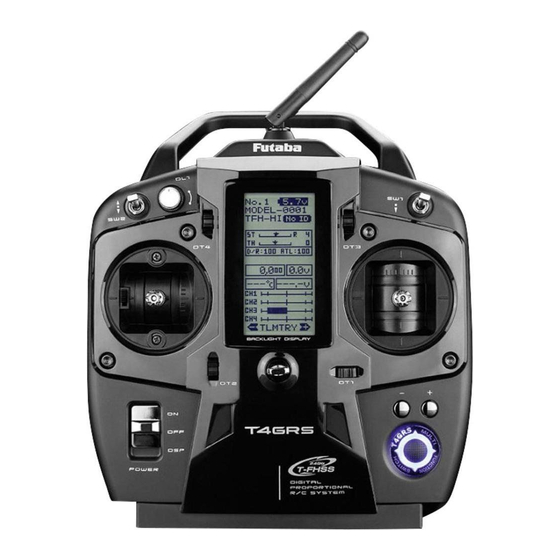
Transmitter T4GRS Nomenclature Antenna Digital Dial 1 (DL1) (default CH4) Switch 2 (SW2) Switch 1 (SW1) (default CH3) Digital Trim 4 (DT4) Digital Trim 3 (DT3) (default ATL) (default dual rate) LCD screen Steering stick Throttle stick Digital Trim1 (DT1) Digital Trim 2 (DT2) (default steering trim) (default throttle trim) -
Page 16: Battery Replacement Method
Battery Replacement Method (4 AA Size Batteries) Load the four batteries in accordance with the po- Battery cover larity markings on the battery holder. Battery Replacement Method Remove the battery cover from the transmitter by sliding it in the direction of the arrow in the figure. -
Page 17: When Using The Optional Battery
When Using The Optional Battery When using an optional rechargeable battery, replace the battery as described below. -Always use the optional HT5F1800B or FT2F1700BV2/2100BV2 rechargeable battery. -The type of power source used must be set by system setting. -When the transmitter will not be used for a long time, remove the battery. Battery Replacement Method Refer to the previous description and remove the transmitter battery cover. -
Page 18: When Charging The Optional Battery
Remove the battery cover. When the battery will not be used for a long time, Disconnect the battery from the 4GRS to prevent it from deteriorating we recommend that it be kept in about the half capacity state in- Balance charging cannot be done through the stead of fully charged. -
Page 19: Low Battery Alarm
Because the low battery alarm voltage of a dry cell battery is different from that of a rechargeable battery pack (genuine Futaba option), the type of power source used must be set by system setting. Warning When a low battery alarm is generated, cease operation immediately and retrieve the model. -
Page 20: Power & Display Switch
Power & Display Switch The power switch and display switch of the T4GRS are inte- grated. In the PWR ON mode, radio waves are transmitted and in the DISP mode, model data, settings can be checked without transmitting radio waves. In addition, some setting menus may only be displayed in the DISP mode. -
Page 21: Display When Power Switch Is Turned On
Display When Power Switch Is Turned On Power switch turned on Battery voltage display Telemetry function :ON/OFF Receiver -> Transmitter: The reception strength is shown. Model number Model name (10 characters) ST :Steering trim display TH :Throttle trim display The current receiver mode is D/R :Steering D/R display displayed. -
Page 22: Stick Operation Ch1 Ch2
Stick Operation CH1 CH2 (CH1: Steering stick, CH2: Throttle stick,) Throttle Stick Function: Controls the speed of the model as well as the direction of travel - forward or reverse. Steering Stick Function: Turns the model right or left. Servo operation of steer- ing channel (CH1)can be checked. -
Page 23: Switch Dial Operation Ch3 Ch4
Switch Dial Operation CH3 CH4 (CH3: Switch SW2, CH4: Dial DL1) The three-position switch SW2 will result in the servo arm moving to three differ- ent positions when operated. Note that this function cannot be assigned to the spring return switch SW1. Rotating the Dial (DL1) will proportionally control a servo on CH4. -
Page 24: Digital Trim Operation
Digital Trim Operation DT1 DT2 (Initial settings: DT1: Steering trim, DT2: Throttle trim,) Operated by the lever: Push the lever to the left or right (up or down) The current posi- tion is displayed on the LCD screen. Steering trim display Throttle trim display •... -
Page 25: Stick Lever Head Adjustment
Stick Lever Head Adjustment The length of the lever head of the steering and throttle sticks can be adjusted. Lever head B Lever head A Adjustment Unlock lever head "A" by turning it counterclockwise. Adjust the head to the length best for you, then lock the heads by turning lever head "A"... -
Page 26: Stick Tension Adjustment
Stick Tension Adjustment Make this adjustment when you want to change the steering stick or throttle stick spring tension. Adjustment Remove the battery from the transmit- ter. Using Phillips screwdriver, as shown in a figure, four screws are removed, and a rear case is removed. -
Page 27: Mechanical Throttle Stick Stroke Adjustment
Mechanical Throttle Stick Stroke Adjustment Make this adjustment when you want to reduce the throttle stick range at the full power or brake/reverse positions. Stick stroke adjustment Make this adjustment by turning the adjusting screw above the stick with a Phillips screwdriver. •... -
Page 28: Neutral Adjuster Operation
mark (fig-4) is displayed, pressing the (JOG) button. ADJUSTER THROTTLE An internal check is performed automatically. When each adjust- N5 5 N7 3 ment point is within a fixed range, correction is performed and "COMPLETE!" (fig-5) is displayed. COMPLETE! If an adjustment point is not within a fixed range, correction is CANCEL Ke y not performed and the correction data is not updated. - Page 29 [ RT ] ton up or down operation. CONTRA BK-LHT LHT-TM LHT-PW UP or DOWN (Selection of your 4GRS neutral position) BATT D RY 4 BUZZER Use the (+) and (-) buttons to select either 5:5 or OPE-TM MENU 7:3.
-
Page 30: Changing To Ratchet Type Throttle Stick
Changing to Ratchet Type Throttle Stick Changing the throttle stick from the self-centering type to ratchet type that stops at an arbitrary position. (To make this modification, the optional ratchet plate must be purchased.) Adjustment Remove the battery from the transmitter. Rear case Using Phillips screwdriver, as shown in a fig- ure, four screws are removed, and the rear... -
Page 31: About Transmitter Antenna And Receiver
About Transmitter Antenna and Receiver About The Transmitter Antenna Position the antenna vertically Antenna to the ground. Antenna Moving Range Warning Position the antenna vertically to the ground. In other positions the operating range may be reduced. Never hold only the antenna. Hold the grip handle. -
Page 32: Receiver Terminology
Under other conditions, the set will not operate, or the specified performance will not be displayed even if it operates. In addition, it may cause trouble with servos and other equipment. Futaba will not be responsible for damage, etc. caused by combination with the products of other companies. -
Page 33: Installation
Installation Receiver and Servo Connections Connect the receiver and servos as shown below. Connect and install the receiver and servos in accordance with "Installation Safety Precautions" on the next page. The figure shown below is an example. The method of connecting the motor controller to the motor and battery depends on the motor controller used. -
Page 34: Installation Safety Precautions
Installation Safety Precautions Warning Receiver (receiver antenna) Do not cut or bundle the receiver antenna wire. Do not bundle the receiver antenna wire together with the motor controller lead wire. Keep the receiver antenna wire at least 1cm away from motor, battery, and other wiring carrying heavy current. Install the receiver antenna holder as closely as possible to the receiver. - Page 35 Warning Connector Connections Be sure the receiver, servo, battery and connectors are fully and firmly connected. If vibration from the model causes a connector to work loose while the model is in operation, you may lose control . Servo Installation When you install the servos, always use the rubber grommets provided in servo hardware bags.
- Page 36 Warning Electronic Speed Control Install the heat sinks where they will not come in contact with aluminum, carbon fiber or other parts that conduct electricity. If the FET Amp (Electronic speed control) heat sinks touch other materials that conduct electricity a short circuit could occur.
-
Page 37: Initial Set-Up
Initial Set-Up Preparations (Transmitter) Before setting the Transmitter functions, check set the following items first. (Display when power switch turned on) When the power switch is turned on, the currently selected model number is displayed. Check if this number is the model number you want to set-up. To change the model number, use the Model Select function. -
Page 38: Receiver Type Change
If the receiver used and the RX type settings are different, change the RX type using the "RX MODE" function. Which RX type is set can be checked at the HOME screen. T-FHSS Normal speed T-FHSS High speed S-FHSS Normal speed S-FHSS High speed FHSS T-FH (NORM) - Page 39 *When using an FHSS (R603GF/R2004F, etc.) or S-FHSS(SFH) system (R2104GF, R204GF-E, etc.) receiver, after the end of setting up to here set the transmitter power switch to OFF and go to "Receivers other than T-FHSS" . Bring the transmitter and receiver to within 50cm of each other (do not allow the anten- nae to touch) and turn on the receiver power.
- Page 40 Precaution: If there are many Futaba 2.4GHz systems (T-FHSS/ S-FHSS/ FHSS) turned on in close proximity to your re- ceiver then it might not link to your transmitter. In this case, even if the receiver’s LED stays solid green, unfor- tunately the receiver might have established a link to one of other transmitters.
-
Page 41: Throttle Mode Check
Throttle Mode Check *This function is not available in "TH-STK : F10 mode". The throttle servo travel can be set to 5:5 or 7:3 for throttle stick operation as required by the throttle mode function . F5/B5 F7/B3 7 : 3 5 : 5 Forward side Brake side... - Page 42 - Steering dual rate (DT3) check At initial set-up, steering dual rate (D/R) is assigned to the DT3. Operate the lever and check if the D/R value displayed on the screen changes. After checking D/R, set the steering dual rate to 100%. - Throttle ATL (DT4) check At initial setting, throttle ATL (ATL) is assigned to the DT4.
-
Page 43: Function Map
Function Map Operation Of Screen In this instruction manual, Edit Buttons are represented by the symbols shown below. The (JOG) button can be operated in the 4 directions up, down, left, and right. (JOG) button left (-) button (+) button (JOG) button right (JOG) button up (JOG) button down... -
Page 44: Selecting Items On The Menu Screen
Selecting Items On The Menu Screen The item indicated by the highlighted cursor on the screen is selected. The cursor is moved using the (JOG) button in up or down movements. The cursor movement figure shown below is an example of the MENU 1 screen. However, move- ment of the cursor is the same in all of the screens. -
Page 45: Basic Menu Japanese Katakana Character Display
Basic Menu Japanese Katakana Character Display On the system menu, the basic menu screen shown below can be displayed in Japanese katakana characters. "KATAKANA" Alphabetic characters characters SPEED TH A.B.S TH A.B.S TH ACCEL END POINT TRIM REVERSE D/R ATL D/R ATL FAIL SFE CH3 /CH4... -
Page 46: Function List
DUAL ESC Front and rear ESCs mixing P-84 GYRO ESC The sensitivity of Futaba car rate gyros can be adjusted. P-86 CPS ESC The CPS-1 of Futaba LED controller can be adjusted. Throttle servo forward side and brake side operation rate setting/ Neutral brake/ Idle... -
Page 47: Functions
Function Model "MODEL" Forty model data (data for 40 R/C cars) can be saved in the T4GRS transmitter. This menu selects the model, copies data between models. Model Menu Display The MENU 1 screen is displayed using (JOG) button up, down, left, or right operation at the HOME screen. -
Page 48: Model Selection "Select
Model Selection "SELECT" Forty model data (model data for 40 R/C cars) can be saved in the 4GRS transmitter and used when the relevant model data is called. Using the model select function - Display the MODEL screen. (Selection of model select) Move the cursor to "SELECT"... -
Page 49: Model Copy "Copy
Model Copy "COPY" The contents of the currently selected model data can be copied to another model. Using the model copy function - Display the MODEL screen. (Selection of model copy) Move the cursor to "COPY" using the (JOG) button up or down operation. Move the cursor to "COPY"... -
Page 50: Model Memory Copy Model Reset "Reset
Model Reset "RESET" This function resets and initializes the contents of the currently selected model data. However, the adjuster function (ADJUSTER), system setting (SYSTEM), and type of receiver mode (TYPE) are not initialized. Using the model reset function - Display the MODEL screen. (Selection of model reset) Move the cursor to "RESET"... -
Page 51: Model Name "Mdl Name
Model Name "MDL NAME" This function allows you to assign a ten character name to each model memory and user name. Display to "MDL NAME" screen by the following method: (MENU 2 screen) (MENU 1 screen) (MDL NAME screen) (HOME screen) Model name User name Press... -
Page 52: Servo Reverse "Reverse
Servo Reverse "REVERSE" (All channel) This function reverses the direction of operation of the servos related to transmitter steering, throttle, and channel 3 /4 operation. However, when the position set by trim or subtrim shifts from the center, the center becomes the opposite side. Display to "REVERSE"... -
Page 53: Subtrim "Subtrim
Subtrim "SUBTRIM" (All channel) Use this function to adjust the neutral position of the steering, throttle, channel 3 and channel 4 servos. 90° *Subtrim adjusts the entire range of the servo in the set direction. Use to adjust the neutral position Display to "REVERSE"... -
Page 54: End Point Adjuster "End Point
End Point Adjuster "END POINT" (EPA) (All channel) Use this when performing left and right end point adjustments, throttle high side/ brake side operation amount adjustment, channel 3 and channel 4 servo up side/ down side operation amount adjustment during linkage. - Correct the maximum steering angle for left and right steering angles when there is a difference in the turning radius due to the characteristics, etc. -
Page 55: End Point Adjustment
Display to "END POINT" screen by the following method: (MENU 2 screen) (MENU 1 screen) (END POINT screen) (HOME screen) Press Select "END POINT" Press Press Press Setting item selection (Steering and Throttle direction) - The direction (STR LFT and STR RGT) linked with the steering stick is switched. - The direction (THR FWD and THR BRK) linked with the throttle stick is switched. -
Page 56: End Point Adjustment
Throttle (END POINT) adjustment (Preparation) - Before setting the throttle end point adjustment (END POINT), set the throttle ATL (initial setup: DT4) to the maximum throttle angle position 100%. - Select the setting item "FWD" by the (JOG) button up or down operation and make the following adjustments: (HOME screen) Throttle (full power) adjustment... -
Page 57: Fail Safe Function "Fail Safe
Fail Safe Function "FAIL SAFE" (All channel) Fail Safe Mode (F/S) This function moves each servo to a preset position when the receiver does not receive a clear signal from the transmitter. -When the condition set at "FHSS" is Rx type, fail safe (F/S) can be set only for throttle (TH). Other channels are set to the normal mode. - Page 58 Fail safe mode selection FAIL SAFE screen (Preparation) - Select the channels "MODE" to be set using the (JOG) button up, down, left, or right operation. (Mode selection) Select the mode by (+) or (-) button. (Each channel can be individually set.) When completed, move the cursor to [RT] us- ing the (JOG) button, and return to the MENU1 screen by pressing the (JOG) button.
-
Page 59: Exponential Adjustment "Exp
Exponential Adjustment "EXP" (Steering/ Throttle system) This function is used to change the sensitivity of the servo around the neutral position. Display to "EXP" screen by the following method: (MENU 2 screen) (MENU 1 screen) (EXP screen) (HOME screen) Press Select "EXP"... - Page 60 FWD (Throttle Forward Side EXP) BRK (Throttle Brake Side EXP) This function is used to change the sensitivity of the throttle/brake servo/ESC around the neutral position. It has no effect on the servo maximum operation amount. Advice When the course conditions are good and the surface has good grip, set each curve to the + side (faster initial response).
- Page 61 Throttle brake side EXP adjustment (Preparation) *This function is not available in "TH-STK : F10 mode" - On the EXP screen make the following adjustments: Select the setting item "BRK" using the (JOG) button up or down operation. Adjustment range -100 ~ 0 ~ +100% Use the (+) button to adjust for a faster initial throttle re- sponse or use the (-) button for a gentler throttle response.
-
Page 62: Servo Speed "Speed
Servo Speed "SPEED" (Steering system) This function is used to change the servo speed. Display to "SPEED" screen by the following method: (MENU 2 screen) (MENU 1 screen) (SPEED screen) (HOME screen) Select Press "SPEED" Press Press Press Setting item STR TURN :Steering application STR RETN... - Page 63 Steering Speed adjustment (Preparation) - On the SPEED screen make the following adjustments: "TURN" direction adjustment On the SPEED screen, Select the setting item STR "TURN" Adjustment range using the (JOG) button up or down operation and use the (+) 1~100% (each direction) or (-) buttons to adjust the delay amount.
- Page 64 THR (Throttle Speed) Sudden throttle stick operation on a slippery surface will cause the wheels to spin, resulting in poor acceleration. Setting the throttle speed With "SPEED": Quick start without skidding function reduces wasteful battery consumption while at the same time enabling smooth, enjoy- able operation.
-
Page 65: Throttle Acceleration "Th Accel
Throttle Acceleration "TH ACCEL" (Throttle system) The throttle servo will "jump" to a preset position at its maximum possible speed. Un- like exponential, which adjusts the whole throttle movement into a curve, throttle ac- celeration simply "jumps" away from neutral and then leaves the remaining response linear. - Page 66 Throttle acceleration adjustment (Preparation) - On the TH ACCEL screen make the following adjustments: (Forward acceleration amount adjustment) Forward acceleration amount Select the setting item FWD "RATE" using the (FWD) (JOG) button up or down operation and use 0~100 the (+) and (-) buttons to adjust the accelera- Initial value: 0 tion amount.
-
Page 67: A.b.s. Function "Th A.b.s
*This function is not available in "TH-STK : F10 mode". A.B.S. Function "TH A.B.S" (Throttle system) When the brakes are applied while cornering with a 4 Wheel Drive or other type of vehicle, understeer may occur. This under- steer can be eliminated and cornering improved using this func- tion. - Page 68 - DELY : Delay Sets the delay from brake operation to ABS operation. When set to 0%, the ABS func- tion is activated without any delay. At 50%, the ABS function is activated after a delay of approximately 1 second and at 100%, the ABS function is activated after a delay of approximately 2 seconds.
-
Page 69: Switch Setting
(Cycle speed adjustment) CYCL Cycle speed (CYCL) Select setting item "CYCL" 1 ~ 30 using the (JOG) button up or Initial value: 10 Adjustment buttons down operation. Use the (+) or - Use the (+) and (-) buttons to (-) button to adjust the pulse make adjustments. - Page 70 Fail Safe Unit When the T4GRS is used with the Futaba fail safe unit (FSU), it will operate as de- scribed below. However, FSU-1 cannot be used in the high speed mode. - When the FSU is connected to the throttle channel, and the A.B.S. function has been activated, the FSU LED will flash each time the servo operates.
-
Page 71: Channel 3/4 "Ch3/Ch4
Channel 3/4 "CH3/CH4" (3/4 channel) The channel 3/4 servo position can be set from the transmitter. When CH3 is as- signed to a dial by the switch dial function , this setting is linked to that dial. When CH3/4 is not assigned to a dial, it can be set with this screen. When CH3/4 is assigned to a switch by the switch dial function, you cannot adjust the CH3/4 via the screen. -
Page 72: Steering Dual Rate/ Throttle Atl "D/R Atl
Steering Dual Rate/ Throttle ATL "D/R ATL" D/R (Steering dual rate) The steering left and right servo travels are adjusted simultaneously. This setting is linked to transmitter DT3. When DT3 is assigned another function, dual rate can be adjusted with this screen. ATL (Throttle ATL) This function decreases the set value when the braking effect is strong and increas- es the set value when the braking effect is weak. -
Page 73: Select Switch Dial Function "Sw/ Dial
Select Switch Dial Function "SW/ DIAL" Selection of the function to be performed by digital trim (DT1, DT2, DT3, DT4) dial (DL1) and switch (SW1, SW2). - The functions that can be assigned to dial, digital trim and switch are listed on the next page. - The dial and digital trim step amount can be adjusted. - Page 74 Adjust button Function select switch setting Adjust with the (+) and (-) but- tons. (Setting SW selection) Select the SW you want to set using the (JOG) button up or SW1 function selection Direction of operation set- down operation. ting (Function setting) Select the function with the (+) or (-) button.
- Page 75 Set table functions (SW1) Abbreviation used on setup screen Function name, etc. NT-BRK Neutral brake function ON/OFF A.B.S function ON/OFF IDLE Idle up function ON/OFF PRGMIX Program mixing function ON/OFF TH-OFF function ON/OFF Throttle off (engine cut) Channel 3 Channel 4 4WS MIX 4WS mixing type select TIMER...
-
Page 76: Brake Mixing "Brake Mix
*This function is not available in "TH-STK : F10 mode". Brake Mixing "BRAKE MIX" (Throttle, 3rd /4th channel system) This function is used when the front and rear brakes must be adjusted independently such as with a 1/5 scale GP car. This mixing uses the 2nd CH for the rear brakes and the 3rd or 4th CH for the front brakes, or controls the front brakes with the 3rd CH and 4th CH servos, or controls the 2nd CH by independent throttle and controls the rear and front brakes with the 3rd CH and 4th CH. - Page 77 Brake mixing adjustment (Brake mixing function ON/OFF) Function ON/OFF (MODE) Using the (JOG) button, select "MODE" of <CH3> for CH3 INH, ACT Select button brake and "MODE" of <CH4> for CH 4 brake. - Select with the (+) or (-) but- Use the (+) or (-) button and set the function to the "ACT"...
-
Page 78: Programmable Mixing "Prog Mix
Programmable Mix "PROG MIX" (All channels) This function allows you to apply mixing between the steering, throttle, channel 3 and channel 4. Additional Functions -When the steering or throttle channel is the master channel (channel that applies mix- ing), trim data can be added. (Trim mode) - The mixing mode selection. - Page 79 (Master channel) Select setup item "MST" using the (JOG) but- ton up or down operation, and select the mas- Channel selection (MST) ter channel by pressing the (+) or (-) button. STR, THR, CH3, CH4 Initial value :STR Select button - Select with the (+) or (-) but- These setup items are different dep- tons.
-
Page 80: 4Ws Mixing "4Ws
4WS Mixes "4WS" (Steering, 3rd channel system) This function can be used with crawlers and other 4WS type vehicles. It is mixing which uses the 1st CH to control the front axle steering and the 3rd CH to control the rear axle steering. - Page 81 (4WS type selection) < NO SW > Select the setting item "MODE" using the I f f u n c t i o n ’s O N / O F F switch is not selected, (JOG) button up or down operation. Use the <NO SW>...
-
Page 82: Dual Esc Mixing "Dual Esc
Dual ESC Mixing "DUAL ESC" (Throttle system) This function is mixing used with crawlers and other 4WD type vehicles and uses the 2nd CH to control the front motor controller and the 4th CH to control the rear motor controller. Front drive only, rear drive only, or both front and rear drive can be selected using any programmed DT (digital trim) button. - Page 83 The programmed DT button is used to select the drive type as shown in the figure below. Rear rate (RATE) 0 ~ 120 (Rear drive travel adjustment) Initial value:100 Select the setting item "RATE" by the (JOG) button up or Adjustment buttons - Use the (+) and (-) buttons to down operation.
-
Page 84: Gyro Mixing "Gyro Mix
Gyro Mixing "GYRO MIX" (Steering system) This function is a remote gain function which adjusts the sensitivity of the Futaba car rate gyro at the T4GRS side, and is mixing that uses the 3rd CH to adjust the gyro sensi- tivity. - Page 85 Setup items Gyro mixing adjustment MODE : Gyro mode (Preparation) NORM : Normal mode gain AVCS : AVCS mode gain - Refer to the gyro instruction manual and connect the gyro to the receiver. When using remote gain, connect gyro sensi- tivity adjustment to the 3rd CH of the receiver.
-
Page 86: Cps Mixing "Cps Mix
CPS Mixing "CPS MIX" This function controls the Futaba CPS-1 channel power switch. Normally, when using the CPS-1 unit to power the vehicle lights etc (LED) the CPS- 1 unit with LED connected is connected to a vacant switch channel and the LEDs are turned on and off by the switch while the vehicle is running. - Page 87 (Control system setup) Function selection (MODE) Operate the (JOG) button up and down and select the setting INH, CH4 FUNC, STR NTR, STR END, THR NT, THR FWD, item "CTRL". Use the (+) or (-) button and select the function. THR BRK, TH NT+BK Select button - Select with the (+) or (-) but-...
-
Page 88: Throttle Mode "Th Mode
Throttle Mode "TH MODE" (Throttle system) This menu has the following 4 functions: - Servo neutral mode, which sets the throttle neutral ratio to 7:3 or 5:5 - Idle up, which raises the idling speed when starting the engine to improve engine start- ing performance of a gasoline car (boat) - Neutral brake, which applies the brakes at the neutral position of the throttle stick - Throttle off (engine cut), which stops the engine of a boat, etc. -
Page 89: Idle-Up "Idlup
However, considering safety, and to prevent the motor from rotating instantly when the power was turned on, the MC950CR, MC851C, MC602C, MC402CR, and other Futaba MC (Motor Controllers) will not enter the operation mode if the neutral position is not confirmed. -
Page 90: Neutral Brake "Ntbrk
However, when using the MC950CR, MC851C, MC602C, MC402CR, or other Futaba MC (Motor Controller), confirm that the MC is in the neutral position and the set is in the operation mode before setting the neutral brake function switch to ON, the same as the idle up function. -
Page 91: Throttle Off (Engine Cut) "Thoff
Throttle Off (engine cut) "THOFF" This is a function select switch dial function. The throttle off function ON/OFF switch must be set. The engine cut function stops the engine of a boat, etc. by operating the throttle servo to the slow side by switch regardless of the position of the throttle stick and the setting of other functions (reverse function setting is effective). -
Page 92: Esc Link Function "Mc Link
ESC Link Function "MC LINK" This is a special function which lets you set the contents of the Link software in Futaba speed controller (ESC), MC960CR, MC940CR, MC950CR, MC851C, MC602C, MC402CR, etc, with variable frequency and other data changes at the T4GRS transmitter. - Page 93 -Select the setting item "MODE" using the (JOG) button, and select "READ" by (+) or (-) button. -Select the setting item "EXEC:+/-" using the (JOG) but- ton, and press the (+) and (-) buttons simultaneously for 1 second or longer. -"COMPLETE!"...
- Page 94 ESC function setup (MC601/602/850/851C, 401/402/950CR) Setup item selection Select the setting item using the (JOG) button. - Select by the (JOG) button. Set the value by (+) and (-) button. The currently set item is Adjustment buttons displayed here. - Use the (+) and (-) buttons to make adjustments.
- Page 95 LBP-(LOW BATTERY VOLT) 2.5V~6V DBA-(DEAD BAND) ±2μs~±50μs 2.5V~7.5V for MC950CR Same as Link software Dead Band. This sets the range (neutral point range) over which the Same as Link software Low Bat Protection ESC does not respond to transmitter throttle operation. This setting cuts off the output to the motor when The larger the set value, the wider this range.
- Page 96 ESC function setup (MC940CR, MC960CR) Setup item selection Select the setting item using the (JOG) button. - Select by the (JOG) button. Set the value by (+) and (-) button. Operate the following (JOG) button and switch between Adjustment buttons - Use the (+) and (-) buttons to Page1 and Page2 of the setup screen.
- Page 97 "MIn" which sets the frequency when the load is small, is set to the high frequency side (large value) when extension is desired after straight- aways and curves. "MAX" which sets the frequency when the load is large, is set to the high frequency side (large value) when you want to suppress the rise from low speed and when motor heating and commutator roughness are sensed.
- Page 98 Page1 TBM-(TURBO MODE) OFF /LV1 /LV2 Same as Link software Turbo Mode This function sets the turbo mode. More power can be enabled using the turbo mode. Depcompleted on the setting, the motor and ESC may be damaged so use this setting carefully. (Note) When LAU (LEAD ANGLE USE) is off, lead angle setting will not operate even if set to LEV1 or LEV2.
- Page 99 LAU-(LEAD ANGLE USE) ON /OFF Same as Link software Lead Angle Use This function is effective when TBM (Turbo Mode) is LEV1 or LEV2 and sets whether or not lead angle is used. This setting has priority over the TURBO MODE setting. When using in races in which the lead angle func- tion is inhibited by the ESC set this function to OFF.
-
Page 100: Data Transfer "Mdl Trans
Data Transfer "MDL TRANS" This function copies the model memory data of one T4GRS to another T4GRS. Con- nect the communication port of both T4GRS together with the optional DSC cord for T4PK. Use this function with the T4GRS power switch set to the display side. Note: If the T4GRS battery voltage drops, the display switches to low battery display. - Page 101 (Select the setting item ) "MODE" by the (JOG) button up or down op- Mode selection eration, and select the transfer side and re- "TRANSFER" "RECEIVE" ceive side by (+) or (-) button. Setup item selection - Select by (JOG) button up or down operation.
-
Page 102: Timer Function "Timer
Timer Function "TIMER" Use the timer by selecting one of the three timers UP TIMER, DOWN TIMER, and LAP TIMER. Display " TIMER " screen by the following method: (MENU 1 screen) (MENU 2 screen) (TIMER screen) (HOME screen) Press Select Press "TIMER"... - Page 103 FUEL DOWN TIMER function Fuel down timer function - This function is primarily used to check the refueling time of a gasoline car. (The remaining time is displayed.) - Each time the switch is pressed, the timer is restarted and the set time is reset.
- Page 104 Timer screen Timer selection First, select the type of timer at the "TYPE" item. The setup screen varies depcompleted on the type of timer. This figure shows the UP TIMER setup screen. Time display Minute display (m) Second display (s) 1/100 second display Status display RST :Reset state...
- Page 105 Using the up timer (Preparation) Adjustment buttons - Use the (+) and (-) buttons to Select the setting item "TYPE" using the (JOG) button. make adjustments. - Press the (+) and (-) buttons si- Press the (+) or (-) button and select "UP". multaneously (approx.
- Page 106 Using the fuel down timer (Preparation) Adjustment buttons - Use the (+) and (-) buttons to Select the setting item "TYPE" using the (JOG) button. make adjustments. - Press the (+) and (-) buttons si- Press the (+) or (-) button and select "DOWN". multaneously (approx.
- Page 107 Adjustment buttons Using the Lap timer - Use the (+) and (-) buttons to (Preparation) make adjustments. - Press the (+) and (-) buttons si- Select the setting item "TYPE" using the (JOG) button. multaneously (approx. 1 sec) to Press the (+) or (-) button and select "LAP". return to the HOME screen.
-
Page 108: Lap List "Lap List
Lap List "LAP LIST" The lap list is displayed when checking the lap memory data (lap times) memorized by lap timer operation. - After the lap timer starts, the lap times are memorized sequentially each time the switch is operated. - If the timer is stopped after the set ALRM time has elapsed, the final lap time is mem- orized and the total time after the last lap is automatically written. -
Page 109: System Functions "System
System Functions "SYSTEM" The graphic liquid crystal screen display mode, buzzer sound and menu character mode, etc. can be set. - "CONTRA"---Liquid crystal screen contrast adjustment (20 steps) - "BK-LHT"---Liquid crystal screen backlighting display mode setup (OFF, ON at button operation, normally ON) - "LHT-TM"---Setting of ON time (1~30 secs) when [ON at button operation] was selected above. - Page 110 System function setup SYSTEM [ RT ] (Setting the liquid crystal backlighting mode) CONTRA Backlight mode (BK-LHT) BK-LHT Select the setting item "BK-LHT" using the (JOG) LHT-TM KEY, ALL, OFF LHT-PW button, and select the mode by pressing the (+) BATT DRY4 or (-) button.
- Page 111 Note: If used with the incorrect setting, a normal low battery alarm will not be gen- erated and the system may stop before the battery alarm is generated. The usage time may also become extremely short. "LiFe2" :Futaba LiFe type battery (FT2F1700BV2 / 2100BV2) "NiMH5" :Futaba MiMH type battery (HT5F1800B) "DRY4"...
- Page 112 SYSTEM [ RT ] (Changing the menu character display) CONTRA BK-LHT Select the setting item "MENU" using the LHT-TM LHT-PW (JOG) button, and set the basic menu char- Menu character (MENU) BATT DRY4 ENG, acter display with the (+) or (-) button. BUZZER OPE-TM "ENG"...
-
Page 113: Adjuster "Adjuster
If an adjustment point is not within a fixed range, correction is not performed and the correction data is not updated. When button mark is not displayed even though correction was performed again, please contact a Futaba Radio Control fig-4 Customer Center. - Page 114 If an adjustment point is not within a fixed range, correction is not performed and the correction data is not updated. ADJUSTER When button mark is not displayed even though correction THROTTLE was performed again, please contact a Futaba Radio Control N5 5 N7 3 Customer Center. COMPLETE!
-
Page 115: Telemetry "Telemetry
Telemetry "TELEMETRY" With the telemetry system, the running status can be displayed at the transmitter and also recorded as a data log by mounting various sensor units to the chassis. The telemetry related screens are only displayed when the T4GRS power switch is in the PWR ON position. -
Page 116: Telemetry/Log Screen Map
Telemetry/Log Screen Map (HOME screen) Press (Telemetry Function ON/OFF Screen) Press p.117 Press The cursor on [RT] The cursor on [RT] Press Press (Sensor Set Screen) p.118 Press Press (Log Data Screen) (Log Set Screen) p.120 Press Press Press Telemetry "TELEMETRY"... -
Page 117: Telemetry Function On/Off
Telemetry Function ON/OFF The telemetry data can be viewed at the HOME screen and telemetry ON/OFF screen. The telemetry function can also be turned on and off at the telemetry ON/OFF screen. The telemetry ON/OFF and communication status can be checked at the HOME screen. The reception strength High No signal reception... -
Page 118: Telemetry Sensor Setting
Telemetry Sensor Setting An audible alarm can be generated by the T4GRS from the data from a telemetry sen- sor. This setting sets alarm ON/OFF and the alarm conditions. Refer to the map on page 116 for the sensor setting (SENS MODE) screen display. There are receiver power source (battery) voltage and external power source (drive bat- tery) voltage settings on page 1 of the sensor setting screen and temperature and speed settings on page 2. - Page 119 Setting external power supply voltage alarm Display page 1 using (JOG) button left or right operation. Alarm ON/OFF Select "ALRM" of the "EXT VOLT" setting ON, OFF - Select with the (+) or (-) but- items using (JOG) button up or down opera- tons.
-
Page 120: Log Setting Start/Stop
Setting the gear ratio Display page 2 using (JOG) button left or right operation. Select "RATIO" of the "R.P.M" set- ting items using (JOG) button up or down op- Gear ratio (moderating ratio) eration, and set the location the sensor is to 0.001~64 actually measure and the gear ratio of the mo- Initial value: 1... - Page 121 Log recording cycle (Recording cycle setting) 0.1~60s( Select the "CYCL" setting item using (JOG) 0.1~10s( )0.1s step button up or down operation, and set the data 10s~60s(sec)1s step Initial value: 1.0 acquisition interval from a minimum 0.1 sec- Adjust button ond to a maximum 60 seconds with the (+) - Adjust with the (+) and (-) but- button or (-) button.
-
Page 122: Log Data List
Log Data List The log data list can be called up when checking the log data memorized by logging op- eration . The maximum log data is up to 200 counts. Refer to the map on page 116 for the log list screen. Example: Receiver power supply voltage log list screen. -
Page 123: Reference
Under other conditions, the set will not operate, or the specified performance will not be displayed even if it operates. In addition, it may cause servo trouble. Futaba will not be responsible for damage, etc. caused by combination with the products of other companies. -
Page 124: Warning Displays
Always set the battery type to "N5/L2" especially when using a Futaba rechargeable type battery. If the set is used at "DRY4" setting, the time from low battery alarm to system stopping will become ex-... - Page 125 Memory Error If the data in the transmitter is not transferred normally LCD screen: when the power is turned on, an audible alarm will sound and "MAIN MEMORY ACCESS ERROR" will be displayed on the LCD. - To stop the alarm, turn off the power. - Turn the power back on.
-
Page 126: Optional Parts
Optional Parts The following parts are available as 4GRS options. Purchase them to match your appli- cation. For other optional parts, refer to our catalog. Transmitter Battery When purchasing a transmitter battery use the following: Part name HT5F1800B (6V/1800mAh) NiMH battery FT2F1700V2(6.6V/1700mAh)/2100BV2 (6.4V/2100mAh) LiFe battery... - Page 127 The responsible party for the compliance of this device is: Futaba Service Center 3002 N Apollo Drive Suite 1, Champaign, IL 61822 U.S.A TEL (217)398-8970 or E-mail: support@futaba-rc.com (Support) CAUTION: To assure continued FCC compliance: Any changes or modifications not expressly approved by the grantee of this device could void the user’s authority to operate the equipment.
Need help?
Do you have a question about the 4GRS and is the answer not in the manual?
Questions and answers