Table of Contents
Advertisement
Available languages
Available languages
Quick Links
HD Camera Adaptor
付属の CD-ROM には、CA-FB70 の取扱説明書が PDF 形式
で記録されています。
詳しくは「CD-ROM マニュアルの使いかた」 (9 ページ)を
ご覧ください。
The supplied CD-ROM includes the Operating Instructions for
the CA-FB70 HD Camera Adaptor in PDF format.
For more details, see "Using the CD-ROM Manual" on page 34.
CA-FB70
お買い上げいただきありがとうございます。
電気製品は安全のための注意事項を守らないと、
火災や人身事故になることがあります。
この取扱説明書には、事故を防ぐための重要な注意事項と製品の
取り扱いかたを示してあります。この取扱説明書をよくお読みのうえ、
製品を安全にお使いください。お読みになったあとは、
いつでも見られるところに必ず保管してください。
© 2012 Sony Corporation
4-445-029-01 (1)
取扱説明書 _________________
Operating Instructions _____
JP
GB
Advertisement
Chapters
Table of Contents

Related Manuals for Sony CA-FB70


Summary of Contents for Sony CA-FB70
- Page 1 付属の CD-ROM には、CA-FB70 の取扱説明書が PDF 形式 で記録されています。 詳しくは「CD-ROM マニュアルの使いかた」 (9 ページ)を ご覧ください。 The supplied CD-ROM includes the Operating Instructions for the CA-FB70 HD Camera Adaptor in PDF format. For more details, see “Using the CD-ROM Manual” on page 34. CA-FB70 お買い上げいただきありがとうございます。 電気製品は安全のための注意事項を守らないと、...
- Page 2 日本語 安全のために 安全のために ソニー製品は安全に充分配慮して設計されています。し 警告表示の意味 かし、電気製品はまちがった使い方をすると、火災や感 取扱説明書および製品で 電などにより死亡や大けがなど人身事故につながること は、次のような表示をし があり、危険です。 ています。表示の内容を 事故を防ぐために次のことを必ずお守りください。 よく理解してから本文を 安全のための注意事項を守る お読みください。 ページから ページの注意事項をよくお読みください。 この表示の注意事項を守 定期点検を実施する らないと、火災や感電な 長期間安全に使用していただくために、定期点検を実施 どにより死亡や大けがな することをおすすめします。点検の内容や費用について ど人身事故につながるこ は、お買い上げ店またはソニーのサービス窓口にご相談 とがあります。 ください。 故障したら使用を中止する この表示の注意事項を守 お買い上げ店またはソニーのサービス窓口にご連絡くだ らないと、感電やその他 さい。 の事故によりけがをした り周辺の物品に損害を与 万一、異常が起きたら えたりすることがありま • 煙が出たら す。 • 異常な音、においがしたら •...
-
Page 3: Table Of Contents
目次 ..............4 警告 ..............5 注意 その他の安全上のご注意 ..........7 ................8 概要 ..............8 本機の特長 CD-ROM ......... 9 マニュアルの使いかた ............. 10 各部の名称と働き ............14 システム構成 .............. 17 準備と設定 .........17 カメラ/カムコーダーに取り付ける ....18 カメラコントロールユニット( )を接続する ......19 アクセサリーシューキットを取り付ける ..........20 トランク信号を出力する ..........20 インターカムを使用する ............21 システムを起動する... - Page 4 警告 接続ケーブルや 電源コードを傷つけな い 接続ケーブルや 電源 コードを傷つけると、火災 や感電の原因となります。 • 接続ケーブルや 電源 分解しない、改造しな コードを加工したり、傷 い つけたりしない。 分解や改造をすると、火災 • 重いものをのせたり、 や感電、けがの原因となる 引っ張ったりしない。 ことがあります。 • 熱器具に近づけたり、加 内部の点検や修理は、お買 熱したりしない。 い上げ店またはソニーの • 接続ケーブルや 電源 サービス窓口にご依頼くだ コードを抜くときは、必 さい。 ずプラグを持って抜く。 万一、接続ケーブルや 指定された (カ 電源コードが傷んだら、お メラコントロールユ 買い上げ店またはソニーの ニット)とパワーサプ サービス窓口に交換をご依...
- Page 5 注意 機器への取り付けは正 しく行う 別売の機器の取り付け方法 を誤ると、機器が落下して けがをすることがあります。 下記の機器を取り付けると きは、マニュアルをよく読 内部に水や異物を入れ んだうえ、確実に取り付け ない てください。 • ビューファインダー 水や異物が入ると火災や感 • AC アダプター 電の原因となることがあり コード類は正しく配置 ます。 万一、水や異物が入ったと する きは、すぐに電源を切り、 電源コードや接続ケー バッテリーや 電源コー ブルを足に引っかけると、 ド、および接続ケーブルを 本機の落下や転倒などによ 抜いて、お買い上げ店また りけがの原因となることが はソニーのサービス窓口に あります。 ご相談ください。 充分注意して接続・配置し てください。 油煙、湯気、湿気、ほ こりの多い場所では設 固定ネジを締める 置・使用しない...
- Page 6 指定されたカメラ、カ ケーブル着脱の際に指 ムコーダー以外は接続 を挟まない しない ケーブル着脱時に指を挟む と、けがの原因となる恐れ 指定以外のカメラ、カム があります。 コーダーを接続すると火災 や故障の原因となることが あります。 接続の際は電源を切る ケーブルを接続するときは、 電源を切ってください。感 電や故障の原因となること があります。 不安定な場所に設置し ない ぐらついた台の上や傾いた ところに設置すると、倒れ たり落ちたりしてけがの原 因となることがあります。 また、設置・取り付け場所 の強度を充分にお確かめく ださい。 ケーブルの抜き差しは 慎重に行う ケーブルを乱暴に扱うと、 機器とケーブルの間に指を 挟み、けがの原因となる恐 れがあります。ケーブルの 抜き差しは無理な力をかけ ずに慎重に行ってください。 ケーブルを接続したま まの運用時には最善の 注意をする 接続ケーブルを引っかける と、転倒や落下の原因とな ることがあります。 注意...
-
Page 7: その他の安全上のご注意
その他の安全上の ご注意 本機は「クラス レーザー製品」です。 レーザー機器についてのご注意 ここに規定した以外の手順による制御お よび調整は、危険なレーザー放射の被爆 をもたらします。 注意 指定以外の電池に交換すると、破裂する 危険があります。 必ず指定の電池に交換してください。 使用済みの電池は、国または地域の法令 に従って処理してください。 重要 機器の名称と電気定格は、底面に表示さ れています。 本機の消費電力、 電源出力、および カメラ/カムコーダーへの給電を含む総 消費電力が を超えないようにして ください。 その他の安全上のご注意... -
Page 8: 本機の特長
概要 本機の特長 CA-FB70 カメラアダプター は、 カメラおよびカムコーダーへのケーブ ルレス接続 HXC-D70 カラーカメラ や、ソリッ PMW- ドステートメモリーカムコーダー 本機は、対応カメラ/カムコーダーの 500/350/320 に装着し、 カメラコ バッテリー装着面に装着し、 ピンイ HXCU-FB70 ントロールユニット 間を BATT ンターフェースおよび インター 光ファイバーケーブルで高画質・長距離 フェースを介して入出力信号や電源ライ 伝送するカメラアダプターです。 ンを接続することができます。接続のた めに外付けケーブルを必要としませんの 取り付け可能なカメラ/カムコーダー で、本機の脱着が容易である上、信頼性 本機を取り付けることができるカメラお の高いシステムカメラ運用が可能です。 よびカムコーダーは、以下の通りです。 光ファイバーケーブル接続による長距 HXC-D70 • シリーズ 離信号伝送 PMW-500 シリーズ... -
Page 9: Cd-Rom マニュアルの使いかた
HXCE-FB70 • パワーサプライユニット CD-ROM マニュ と カメラコントロールユニット HXCU-FB70 を敷設のシングルモー アルの使いかた ドファイバーケーブルで接続(最長 ) 10 km )しながら、本機とパワーサ HXCE-FB70 プライユニット を光電 Adobe Reader がインストールされた 気複合ケーブルで接続・給電(最長 コンピューターで、取扱説明書を閲覧で ) 250 m )できます。ご使用環境に合 きます。 わせて、自由度の高いシステム構築が Adobe Reader Adobe は、 のウェブ 可能です。 サイトから無償でダウンロードできま ) 電源供給可能距離は、本機に接続する対応カメ す。 ラ/カムコーダーの機種や、接続するレンズや アクセサリーなどの総合的な消費電力によって... -
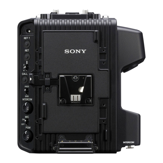
Page 10: 各部の名称と働き
各部の名称と働き ビューファインダー 用 ウェッジシューア タッチメント用ネジ穴 1 ケーブルクランプ TALLY スイッチ 取り付け部 2 アクセサリー取り付け RET 1 ボタン 用ネジ穴 ボタン/ TALLY ランプ RET 2/3/4 切り (赤)/(緑) 換えスイッチ CALL ボタン アダプター取り付 INTERCOM け部 ライン選択スイッチ POWER スイッチ/ ランプ INTERCOM ボリューム スイッチ ボリューム qg カメラ/カムコーダー 固定用ネジ qhカメラ/カムコーダー... - Page 11 a ケーブルクランプ取り付け部 INTERCOM (インターカムレベ 付属のケーブルクランプベルトを取り付 ル)ボリューム けます。 INTERCOM 端子に接続したヘッドセッ トの受信音声レベルを調整します。 b アクセサリー取り付け用ネジ穴 U1/4-20 POWER アクセサリー取り付け用の の (電源)スイッチ/ラン ネジ穴( か所) 、付属のアクセサリー プ シュ―(エレクトロニックビューファイ 本機の電源を入れるときは 側にし、 DXF-C50WA ンダー 用)取り付け用の 本機の電源を切るときは 側にしま ネジ穴( か所) 、別売のコールド す。本機の電源を にすると、カメ X-2546-633- シューキット( )取り付け ラ/カムコーダーに電源供給されませ 用のネジ穴( か所)です。 ん。動作時は、ランプが緑に点灯しま...
- Page 12 (リターンビデオ)ボタンと ビューファインダー用 ウェッ RET 2/3/4 2/3/ (リターンビデオ ジシューアタッチメント用ネジ穴 )切り換えスイッチ ビューファインダー用 ウェッジ シューアタッチメント取り付け用の リターンビデオ と並行して別の系統の 型ネジ穴( か所)です。 システムを使用している場合、 ボ RET 2/3/4 タンを押している間、 スイッ o カメラ/カムコーダー固定用ネジ チで選択した信号をビューファインダー 本機をカメラまたはカムコーダーに固定 に表示します。 します。 RET 1 (リターンビデオ )ボタン p カメラ/カムコーダー接続端子 押している間、 からのリターンビ ( ピン) デオ 信号をビューファインダー画面で カメラのアダプター接続端子またはカム...
- Page 13 t カメラ/カムコーダー固定用ネジ (カメラコントロールユニッ 穴 ト)端子(光電気マルチコネク 本機をカメラまたはカムコーダーに固定 ター) するためのネジ穴です。 ブラケット カメラコントロールユニット のネジを締めます。 HXCU-FB70 に接続します。 光電気複合ケーブルで接続した場合は、 INTERCOM (インターカム)端 電源、コントロール信号、ビデオ信号、 子( 型 ピン) 音声信号など、カメラのすべての信号を XLR 5 ピンタイプのヘッドセットを接続 光電気複合ケーブル 本で送受信できま し、インターカムの音声信号を入出力し す。 ます。 シングルモードファイバーケーブルのみ で接続した場合は、電源を除いたすべて ◆ ピンアサインメントについては、 「ピンアサイ の信号が、シングルモードファイバー INTERCOM ンメント」の「 端子」 ( ペー ケーブル...
-
Page 14: システム構成
プロンプター ビデオ入力 同期信号入力 HD カラーカメラ HXC-D70 光電気複合ケーブル 映像出力 HD カメラ HD カメラ HD SDI/ コントロールユニット アダプター SD SDI/VBS/ HXCU-FB70 CA-FB70 または HDMI AC 電源 ソリッドステートメモリー カムコーダー プロンプター 2 ) 3 ) 3 ) PMW-500 /350 /320 CCA-5 ケーブル / ビデオ出力... - Page 15 同期信号入力 ビデオ入力 HD カラーカメラ HXC-D70 シングルモードファイバー ケーブル(ペア) 映像出力 HD カメラ HD カメラ HD SDI/ コントロールユニット アダプター HXCU-FB70 SD SDI/VBS/ CA-FB70 または HDMI AC 電源 ソリッドステートメモリー プロンプター カムコーダー CCA-5 ケーブル / 2 ) 3 ) 3 ) ビデオ出力 PMW-500 /350 /320 LAN ケーブル...
- Page 16 光電気複合 ケーブル ケーブル HD カメラ 映像出力 HD カメラ パワーサプライ HD SDI/SD コントロール アダプター ユニット SDI/VBS/HDMI ユニット HXCE-FB70 CA-FB70 または HXCU-FB70 AC 電源 ソリッドステートメモリー カムコーダー AC 電源 CCA-5 ケーブル / 3 ) 4 ) 4 ) PMW-500 /350 /320 LAN ケーブル...
-
Page 17: 準備と設定
固定ネジ 準備と設定 カメラ/カムコーダーに 取り付ける カメラまたはカムコーダーの カ バーのネジをゆるめて、 カバー を取りはずす。 カメラまたはカムコーダーのバッテ リー取り付け部に、本機に付属の ブラケットをネジ( 本)で固 定する。 カバー 固定ネジ ご注意 脱落防止のため、ネジを確実に締めてく ださい。 取りはずすには 取り付けと逆の手順で行います。 ブラケット カメラまたはカムコーダーのバッテ リー取り付け部の上部から本機をス ライドさせて装着する。 本機上部( 本)と下部( 本)の固 定ネジを締める。 準備と設定... -
Page 18: Ccu
バックルをはずして、 ケーブル カメラコントロールユ にベルトを巻いて束ね、 バックル ニット( )を接続す を元どおりロックする。 る を使用するシステム運用時は、本 CAMERA 機の 端子と の 端 子を接続します。 必要に応じて、付属のケーブルクランプ ベルトを使用して本機にケーブルを固定 してください。 ケーブルクランプベルトを使う ベルトの下端を引いて長さを調整す には る。 ケーブルクランプベルトの上端の穴 A または B に、 ベルトブラケット C を通す。 本機のケーブルクランプ取り付け 部のネジ穴カバーを取りはずし、 付属のネジ( × ) 本でベ ルトを本機に取り付ける。 準備と設定... -
Page 19: アクセサリーシューキットを取り付ける
アクセサリーシューキッ トを取り付ける エレクトロニックビューファインダー DXF-51 DXF-C50WA および を取り付 けるときは、付属のアクセサリーシュー キットをアクセサリー取り付け用ネジ穴 ( か所)に取り付け、そこにビュー ファインダーを取り付けてください。 シューを取り付けるには ネジ × ストッパーネジ シュー 板バネ アクセサリーシューキットに付属の ネジ( × )で、シューを取り 付ける。 板バネを矢印方向にシューにはめ込 み、ストッパーネジを締め付ける。 準備と設定... -
Page 20: トランク信号を出力する
トランク信号を出力する HXC-D70 カラーカメラ に接続している場合 HXC-D70 TRUNK RS-232C REMOTE RS-422A の 端子( )または 端子( )に接続 TRUNK した外部機器と、 の 端子に接続した外部機器との通信用に使用できま す。 HXC-D70 からトランク信号を出力するには HXC-D70 MAINTENANCE <TRUNK> の下記のメニュー( メニュー : )で制 御します。 Interface 使用する外部機器に合わせて を選択してください。 メニューページ名 項目 設定 説明 <TRUNK> TRUNK TRUNK 信号の出力を無効にします TRUNK 信号の出力を有効にします... -
Page 21: システムを起動する
ご注意 PMW-500/350/320 ソリッドステートメモリーカムコーダー を接続する場合は、ヘッ ドセットの 入力設定が下記の出荷設定に固定されています。 Dynamic / -60dB / Unbalance インターカムシステムとの接続および設定変更については、ソニーのサービス窓口にお 問い合わせください。 システムを起動する 本機をカメラ/カムコーダーに取り付けた後で、本機と を光電気複合ケーブル で接続します。 POWER カメラ/カムコーダーおよび本機の スイッチを にした後で、 の POWER スイッチを にします。 から本機に電源が給電され、本機が起動 します。さらに、本機からカメラ/カムコーダーに電源が給電され、カメラ/カム コーダーが起動します。 POWER 0.5 Hz システム起動中は、 ランプ(緑)が で点滅します。本機とカメラ/ POWER カムコーダーとの機器認証通信が完了すると、 ランプ(緑)が点灯します。 ご注意 POWER カメラ/カムコーダーの スイッチが... - Page 22 HXC-D70 カラーカメラ 接続時 HXC-D70 HXCU-FB70 本機および のビデオフォーマットは、 ( )のフォー マット設定に連動して設定されます。 PMW-500/350/320 2 ソリッドステートメモリーカムコーダー 接続時 PMW-500/350/320 の対応フォーマットには、 および本機が非対応のフォー マットがあります。また、カムコーダーのフォーマット設定は のフォーマット設 定に連動しないため、 のフォーマット設定に合わせて、カムコーダーのフォー マットを設定してください。 ソリッドステートメモリーカムコーダー および本機のビデオフォーマット PMW-500/350/320 動作モード ビデオフォーマット 1920 1080/59.94i 1920 1080/59.94i モード × × HD SDI ( 出力) 1280 × 720/59.94P 1280 ×...
-
Page 23: エラーメッセージ
エラーメッセージ 操作中に異常が検出されたときのエラーメッセージを以下に示します。本機は表示装置 を持たないため、 のメニュー、またはリモートコントロールパネルに表示されま POWER す。本機の表示としては、 ランプ(緑)の点滅で表示します。 POWER ランプ リモートコントロー の表示 内容 (緑) ルパネルの表示 2 Hz 点滅( ) 本機および とカメラ/カム コーダーとのビデオフォーマットが ) 一致しない CHU: RX CARE CAM: RX OPT 2 Hz Optical LEVEL 点滅( ) が低下している CARE CHU: RX CAM: RX OPT 4 Hz Optical LEVEL 点滅(... -
Page 24: 使用上のご注意
のものをかけると、変質したり塗装がは 使用上のご注意 げたりすることがあります。 HXC-D70 カラーカメラ 取り付 け時の注意事項 使用・保管場所 HXC-D70 本機を カラーカメラ に 水平な場所、空調のある場所に保管して HXC-D70 取り付けて使用する場合、 の ください。次のような場所での使用・保 MAINTENANCE メニューにおいて、 管は避けてください。 選択できない信号があります。 • 極端に寒い所、暑い所(本機の使用温 度は− ℃∼+ ℃です。ただし、 ページ名 ページ 項目 選択できない カムコーダー接続時は ℃∼ ℃で 信号 す) <TEST OUTPUT VBS 真夏、窓を閉め切った自動車内は OUT> ℃を越えることがあります。... -
Page 25: 保証書とアフターサービス
保証書とアフター 仕様 サービス 一般 保証書 電源電圧 端子から電源を • この製品には保証書が添付されていま 供給する場合: すので、お買い上げの際お受け取りく DC 48 V ださい。 DC IN 端子から電源 • 所定事項の記入および記載内容をお確 を供給する場合: かめのうえ、大切に保存してくださ 12 V 11 V ( ∼ い。 ) DC 48 V 消費電力 入力時: アフターサービス 75 W 最大 DC 12 V 入力時:... -
Page 26: 付属品
端子 関連機器 HXC-D70 カラーカメラ カメラ/カムコーダー入出力端子 ソリッドステートメモリーカムコーダー カメラ/カムコーダー接続 PMW-500/350/320 ピン(凹) カメラコントロールユニット HXCU-FB70 出力端子 HXCE-FB70 パワーサプライユニット PROMPTER 型、 Ω エレクトロニックビューファインダー DXF-51/C50WA その他の端子 エレクトロニックビューファイン 光電気複合コネクター CBK-VF01 ダー INTERCOM XLR 5 ピン(凹) エレクトロニックビューファイン カメラ/カムコーダー電源供給 HDVF-C550W ダー ピン(凹) AC-DN2B/DN10 アダプター DC 12 V 、最大定格 電流 仕様および外観は、改良のため予告なく... -
Page 27: ピンアサインメント
DC IN 端子 ピンアサインメント INTERCOM 端子 ピ ン 信号 入出力 仕様 番号 EXT DC GND for DC − ピ ン 信号 入出力 仕様 番号 No connection Intercom CARBON No connection MIC (Y)/ − 20 dBu, EXT DC +11 to +17 V )... - Page 28 端子 ピン番号 信号 Optical INPUT Optical OUTPUT DC IN (GND) DC IN (+48V) 仕様...
- Page 29 English Before operating the unit, please read Tämä HD-kamerasovitin on luokiteltu 1. this manual thoroughly and retain it for LUOKAN LASERTUOTTEEKSI. future reference. Den här adaptern för HD-kamera klassificeras som en LASERPRODUKT WARNING AV KLASS 1. To reduce the risk of fire or Caution electric shock, do not expose Use of controls or adjustments or...
- Page 30 Canada. Minato-ku, Tokyo, 108-0075 Japan. The Authorized Representative for Pour les clients en Europe EMC and product safety is Sony Ce produit portant la marque CE est Deutschland GmbH, Hedelfinger conforme à la Directive sur la Strasse 61, 70327 Stuttgart, Germany.
- Page 31 Kennzeichnung und erfüllt die EMV- Richtlinie der EG-Kommission. Pour les clients en Europe Angewandte Normen: Le fabricant de ce produit est Sony • EN55103-1: Elektromagnetische Corporation, 1-7-1 Konan, Minato-ku, Verträglichkeit (Störaussendung) Tokyo, 108-0075 Japon. • EN55103-2: Elektromagnetische Le représentant autorisé...
- Page 32 Table of Contents Overview ..............33 Features ..............33 Using the CD-ROM Manual ........34 Names and Functions of Parts ......... 35 System Configuration ..........39 Preparation and Setting ..........42 Attaching the Adaptor to a Camera/Camcorder ..42 Connecting a Camera Control Unit (CCU) ....43 Attaching the Accessory Shoe Kit ......
-
Page 33: Overview
Overview Features The CA-FB70 HD Camera Adaptor is a Cable-free connection to camera/ camera adaptor that can be attached to camcorder the HXC-D70 HD Color Camera or The adaptor can be installed on the PMW-500/350/320 Solid-State Memory attachment shoe of a camera/ Camcorder. -
Page 34: Using The Cd-Rom Manual
If you have lost or damaged the CD- connectors to allow for live ROM, you can purchase a new one broadcasting, not only with the HXC- from your Sony dealer or Sony service D70 but with standalone camcorders. counter. • Intercom feature (2 switchable lines;... -
Page 35: Names And Functions Of Parts
Names and Functions of Parts qf Screw holes for V-wedge shoe attachment of HD viewfinder 1 Cable clamp qd TALLY switch attachment 2 Accessory screw qs RET 1 button holes 3 TALLY lamp qa RET button / (red)/(green) RET 2/3/4 switch 0 CALL button 4 AC adaptor attachment shoe... - Page 36 a Cable clamp attachment h POWER switch / lamp Attaches the supplied cable clamp belt. Set to ON to turn on the adaptor and set to OFF to turn off. When the adaptor is b Accessory screw holes turned off, power will not be supplied to These comprise of a U1/4”-20 screw the connected camera/camcorder.
- Page 37 l RET 1 button p Camera/Camcorder connector The return video 1 signal from the (50-pin) camera control unit is monitored on the Connect to the adaptor connector of the viewfinder screen while this button is camera or the camera adaptor pressed.
- Page 38 u INTERCOM connector (XLR 5- pin) Used for input and output of intercom audio signals if an XLR 5-pin headset is connected. For information on pin assignment, see “INTERCOM” in “Pin assignment” on page 52. v PROMPTER connector (BNC) For output of the VBS prompter signal when a CCU is connected.
-
Page 39: System Configuration
Intercom Headset RCP-1000-series Remote Control Panel The maximum transmission distance is 250 m (820 ft) when Sony CCFN-25/50/100 Hybrid Fiber Cable is used. An optional CBK-HD02 SDI/COMPOSITE Input and 50 Pin Interface is required. An optional CBK-CE01 50 Pin Interface and Digital Extender is required. - Page 40 Return Video Input AC-DN2B/DN10 AC Adaptor Prompter Sync Input Video Input HXC-D70 HD Color Camera Single-Mode Optical Fiber Cable (Pair) HXCU-FB70 HD SDI/SD CA-FB70 HD Camera SDI/VBS/ HD Camera Adaptor Control Unit HDMI Video Outputs AC Power PMW-500 /350 /320 CCA-5 Cable/...
- Page 41 Intercom Headset RCP-1000-series Remote Control Panel The maximum transmission distance is 250 m (820 ft) when Sony CCFN-25/50/100 Hybrid Fiber Cable is used. The maximum transmission distance is 10 km (32,800 ft) when a general single-mode optical fiber cable with an LC connector is used.
-
Page 42: Preparation And Setting
Attachment screws Preparation and Setting Attaching the Adaptor to a Camera/Camcorder Loosen the screws on the 50P cover of the camera or camcorder, then remove it. Fix the supplied CA bracket on the battery attachment shoe of the camera or camcorder using the two screws. -
Page 43: Connecting A Camera Control Unit (Ccu)
1 Release the buckle, 2 bundle Connecting a Camera the cable with the belt, 3 then lock Control Unit (CCU) the buckle again. When operating the camera in a system with a CCU, connect between the CCU connector of the adaptor and the CAMERA connector of the CCU. -
Page 44: Attaching The Accessory Shoe Kit
Attaching the Accessory Shoe Kit When you attach the DXF-51 or DXF- C50WA Electronic Viewfinder, screw the supplied accessory shoe kit to the accessory shoe holes of the adaptor (four holes), then attach the viewfinder to the accessory shoe. To attach the accessory shoe Screw (K3×6) Accessory Stopper... -
Page 45: Outputting Trunk Signal
Outputting Trunk Signal When connected to the HXC-D70 HD Color Camera You can communicate with an external device that is connected to the TRUNK connector (RS-232C) or REMOTE connector of the HXC-D70, and an external device that is connected to the TRUNK connector of the CCU. To output trunk signal from the HXC-D70 Configure the following menu (MAINTENANCE menu M13: <TRUNK>) of the HXC- D70. -
Page 46: Starting The System
(factory default) values: Dynamic / -60dB / Unbalanced For information on connection to an intercom system and configuration of the settings, contact your Sony dealer. Starting the System 1 Attach the adaptor to the camera/camcorder, then connect the adaptor to the CCU using an optical composite cable. - Page 47 1 When connected to the HXC-D70 HD Color Camera Both the video format setting of the adaptor and HXC-D70 are synchronized with that of the CCU (HXCU-FB70). 2 When connected to the PMW-500/350/320 Solid-State Memory Camcorder As PMW-500/350/320 supports video formats that the adaptor and CCU do not, the video format setting of the camcorder is not synchronized with those of the CCU.
-
Page 48: Error Messages
Error Messages When an error is detected, an error message shown in the below table appears. Since the adaptor does not have a display, the message is displayed in the menu of the CCU or the remote control panel. The adaptor also alarms it by blinking the POWER lamp (green). -
Page 49: Important Notes On Operation
solvents such as thinners, alcohol, Important Notes benzene, and insecticides. They may damage the surface finish or cause it to on Operation peel off. Notes when connecting to the HXC-D70 HD Color Camera When you attach the adaptor to the Use and storage locations HXC-D70 HD Color Camera, the Store in a level, ventilated place. -
Page 50: Specifications
Connectors Specifications Camera/Camcorder input/output connectors Camera/Camcorder connector 50-pin, female General Output connectors Power requirements PROMPTER When supplying power to the BNC type, 75 Ω CCU connector: DC 48 V When supplying power to the Other connectors DC IN connector: 12 V (11 V CCU Optical composite connector - 17 V) INTERCOM... -
Page 51: Other Peripheral Devices
Attention concernant le câble Other peripheral devices optique/électrique composite : Pour la connexion entre l’unité de HXC-D70 HD Color Camera commande de caméra et un adaptateur PMW-500/350/320 Solid-State Memory de caméra, ou entre un bloc Camcorder d’alimentation et un adaptateur de HXCU-FB70 HD Camera Control Unit caméra, utilisez un câble composite de HXCE-FB70 Power Supply Unit... -
Page 52: Pin Assignment
DC IN Note Always verify that the unit is operating properly before use. SONY WILL NOT BE LIABLE FOR DAMAGES OF ANY KIND INCLUDING, BUT NOT LIMITED TO, COMPENSATION OR REIMBURSEMENT ON ACCOUNT OF THE LOSS OF PRESENT OR Signal... - Page 53 Signal Optical INPUT Optical OUTPUT DC IN (GND) DC IN (+48V) Specifications...
- Page 56 Printed in Belgium...