Table of Contents
Advertisement
Quick Links
Advertisement
Table of Contents

Related Manuals for Eneo GLC-1401


Summary of Contents for Eneo GLC-1401
- Page 1 Installation and Operating Manual LAN Camera GLC-1401...
-
Page 2: Table Of Contents
Contents Safety Instructions ..............................3 Product Features ..............................4 2.1 Product Introduction ............................4 2.2 General Description ............................4 Description of the Front/Rear View ........................5 3.1 Front Panel and Rear Panel ..........................5 3.2 RS-232 Port & ALARM I/O ...........................6 3.3 Flank Panel ................................7 3.4 The USB Function ...............................8 Installation................................9 4.1 Connecting with an NVR .............................9 4.2 Connecting with a DVR .............................10... -
Page 3: Safety Instructions
1. Safety Instructions • The instructions below must be followed for your own safety. • Please read the safety instructions and operating instructions before connecting the device and putting it into operation. • Keep the operating instructions safe for use at a later date. •... -
Page 4: Product Features
2. Product Features 2.1 Product Introduction This user-friendly device combines cutting-edge sophistication with practical reliability and convenience, high perfor- mance with smooth remote communication. Just plug in the network cable ! You’ll get live streaming Video & Audio anytime any place ! You’ll have security you can rely on ! The especially high resolution has 480 TV lines, a built-in web server and a Network interface to connect you with the Internet securely and fast. -
Page 5: Description Of The Front/Rear View
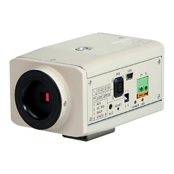
3. Description of the Front/Rear View 3.1 Front Panel and Rear Panel Front Panel Rear Panel 1. Microphone: The LAN CAMERA has an additional audio function. The device has a microphone built into its front panel which records sound. 2. ALARM I/O & RS-232 Port: The RS-232 communication port functions as a connector to an external control device. -
Page 6: Rs-232 Port & Alarm I/O
3.2 RS-232 Port & ALARM I/O RS-485 D- RX: This pin is one of the RS-232 pins. It connects with the TX pin of another device. TX: This pin is one of the RS-232 pins. It connects with the RX pin of another device. Please refer to the note below on the standard RS-232 9 Pin Cable with Pin 2 and Pin 3 exchanged;... -
Page 7: Flank Panel
3.3 Flank Panel Right Flank Panel Left Flank Panel Lens Mount: This LAN CAMERA is used with either C or CS mount lens. ALC VR: Iris control VR When an auto iris (DC Drive) lens is used, this VR is used to adjust the iris for different lighting environments. Adjust the VR clock-wise to open the iris and counter-clockwise to close the iris of the camera. -
Page 8: The Usb Function
3.4 The USB Function By connecting the LANCAM with a PC via the USB connector, the LANCAM can provide two different functions. Insert an SD card: As a card reader Insert an SD card into the LAN CAMERA, then connect to the PC. You might transfer files between the SD card and the PC. -
Page 9: Installation
4. Installation Please follow the instructions and the diagram below to set up the system. NOTE: The LAN CAMERA is linked by its Video Out connection via a BNC connector to a monitor’s Video In connection. If this connection is there, you can see some information on the monitor screen, such as the LAN CAMERA factory default Static IP address (192.168.1.168). -
Page 10: Connecting With A Dvr
4.2 Connecting with a DVR CONNECT TO VIDEO OUT BNC CONNECTOR CONNECT TO DVR VIDEO IN 4.3 Connecting with a Multiplexer LAN CAMERA 1 TO LAN Camera VIDEO OUT BNC CONNECTOR LAN CAMERA 2 LAN CAMERA 16... -
Page 11: Updating System Software
4.4 Updating System Software If the system software of the LAN CAMERA needs to be upgraded, please take the following steps to safely process it. Important: Before carrying out the following procedures, please ensure the SD card is working and the file of system firmware is intact. -
Page 12: Lan Camera Sd Card Troubleshooting
4.5 LAN CAMERA SD Card Troubleshooting Check if the SD card position is correct or not. Please refer to the manual for the related information. After powering the LAN CAMERA on, correctly insert the SD card, and a little icon of „SD” will show up in the upper-right corner of the monitor screen. -
Page 13: Adjustment Of Lenses
4.6. Adjustment of Lenses C mount lens CS mount lens Adjustment of flange This adjustment (distance between lens casing and sensor surface) is required if a sharp focus for fixed focus definition cannot be obtained with the lens focussing, or in order to adjust the ∞ position lenses To obtain a sharp definition, point the camera at an object which is at least 2000 times further away from the front of the lens than the focal length. -
Page 14: Network Configuration
Explanation of terms for iris setting AGC (automatic gain This starts tooperate when the light intensity is insufficient to deliver a full video signal control) (1Vp-p). The greater the gain, the greater the signal noise in the picture. It is generally activated between 0.8 and 1.0Vp-p. -
Page 15: Connect To A Computer
5.1.1 Connect to a Computer Use a crossover LAN cable to connect directly to a computer. CROSSOVER CABLE TO PC LAN CARD CROSSOVER CABLE PIN CONFIGURATION 5.1.2 Connect to a LAN Hub (INTRANET) The RJ-45 PIN configuration for connecting with a LAN Hub is shown below. TO PC NETWORK CARD TO NETWORK HUB/Switch / Router... -
Page 16: Configure Your Lan Camera Network Settings
5.2 Configure your LAN CAMERA Network Settings Upon connecting with the network hardware, you need to activate the network function and configure the proper network settings of the LAN CAMERA. 5.2.1 Enable DHCP Function This function can only work if the LAN, which the unit is connected to, has a DHCP server. If the DHCP server is working, please move the dip switch points up to 3 on the flank panel;... -
Page 17: Tcp/Ip Communication Software
5.3 TCP/IP Communication Software Follow the instructions below to install the TCP/IP communication program into your computer. Click the Start menu from your computer, and point to the Settings/Control panel. Double click the Network icon to enter the windows. -
Page 18: Tcp/Ip Installation
Click the Configuration tag, and check if the TCP/IP is included among the network components list. If the TCP/IP is included, please process section 4.5. If it is not included, please follow section 4.4 to install the TCP/IP. 5.4 TCP/IP Installation During the installation, you will be requested to insert the Windows CD-ROM. -
Page 19: Tcp/Ip Configuration Setting
5.5 TCP/IP Configuration Setting Click Start –> Settings –> Control Panel –> Network Select TCP/IP, and then click Properties. Before processing the LAN CAMERA installation in a WAN, please make sure the Internet connection works properly. If not, please contact your ISP provider. If you are using a DHCP server, please select Obtain an IP address automatically. -
Page 20: Connection Testing
5.6 Connection Testing With the previous settings, follow the instructions below to ensure whether you have established the connection successfully. Click Start –> Programs –> MS-DOS Prompt Type in ping 192.168.1.168 then Enter. (See the sample screen below) • This IP is the LAN CAMERA IP address that is assigned for the connected LAN CAMERA in step 2. - Page 21 If you receive a response as in the sample screen below, the connection hasn’t been successfully established. Please re-check all the hardware and software installation by repeating steps 1 to 5. If you still can’t establish the connection after re-checking, please contact your dealer. If you receive a response as in the sample screen below, you have successfully made the connection.
-
Page 22: Operating Instructions For Image Software And Network
6. Operating Instructions for Image Software and Network Two choices of software are available for linking up with the LAN CAMERA: (1) the Microsoft Internet Explorer; and (2) the LAN CAMERA VIEWER, a network browser in a PC which provides the functions of monitoring remote zones or watching recorded data through the TCP/IP protocol. -
Page 23: Microsoft Internet Explorer
6.1 Microsoft Internet Explorer 6.1.1 Connecting the LAN CAMERA 1. Start up the Microsoft Internet Explorer, and then follow the steps below to connect the LAN CAMERA. 2. Click the URL block at the top of the window. 3. Enter the URL address of the LAN CAMERA into the URL block and press the „Enter” button to enter the home page. 4. - Page 24 Browsing images from the LAN CAMERA The images from the LAN CAMERA will be displayed on the home page while going online with the LAN CAMERA. Some buttons provided at the bottom of the home page for further setting. In MJPEG mode or in MPEG4 mode, there are different display formats of its home page.
-
Page 25: Change Image Setting
6.1.2 Change Image Setting Please follow the steps below to change the image setting through the network if and as necessary. 1. Click the image button on the home page to enter the image-setting page. Image setting page of MJPEG mode Image setting page of MPEG4 mode 2. - Page 26 5. Click the Privacy Mask button to enter the Privacy Mask page. 6. Click the Home button to return to the home page while the new image setting acts on the images to effect the desired changes instantly. (If the setting has not been changed by the above steps, any (re)entry onto the home page will find images in their earlier or original setting.) Exchange the image format 1.
-
Page 27: Change The Network Setting
6.1.3 Change the Network Setting Please follow the steps below to change the network setting through the network if and as necessary. • Set the network options and IP address 1. Click the network button in the home page to enter the network-setting page. 2. - Page 28 • Change the Network Setting - FTP (MJPEG mode only) Please follow the steps below to change the FTP setting via the network if necessary to upload recording data live. 1. Click the FTP button at top left to enter the „FTP Server Setting” page. 2.
- Page 29 • Change the Network Setting - SMTP (MJPEG mode only) Please follow the steps below to change the SMTP setting through the network if necessary. 1. Click the SMTP button at upper left above to enter the „SMTP Server Setting” page. 2.
- Page 30 • Change the Network Setting - SNTP Please follow the steps below to change the SNTP setting through the network if and as necessary. 1. Click the SNTP button at upper left above to enter the „SNTP SERVER SETTING” page. 2.
- Page 31 • Change the Network Setting - DDNS The „Network” page has, on its upper left, the „DDNS” icon. Please follow the steps below to change the DDNS setting through the network if and as necessary. 1. Click the DDNS button at upper left above to enter the „DDNS SETTING” page. 2.
- Page 32 • Change the Network Setting - PPPoE The „Network” page has, on its upper left, the „PPPoE” icon. Please follow the steps below to change the PPPoE setting through the network if necessary. 1. Click the PPPoE button at upper left above to enter the „PPPoE Setting” page. 2.
-
Page 33: Change The System Setting
6.1.4 Change the System Setting Please follow the steps below to change the date and time of the system setting through the network if and as necessary. • Set the Date and Time of the system 1. Click the system button in the home page to enter the „System - Date and Time” page (default). 2. - Page 34 • Change the System Setting - Timestamp Please follow the steps below to change/add the timestamp through the network if necessary. 1. Click the Timestamp button on the left side of the „System - Date and Time” page to enter the „System- Timestamp”...
- Page 35 • Change the System Setting - Users Please follow the steps below to change/add the users’ authority through the network if necessary. 1. Click the Users button on the left side of the „System - Date and Time” page to enter the „System - Users” page. 2.
- Page 36 • Change the System Setting - Digital I/O Please follow the steps below to change the Digital I/O through the network if necessary. 1. Click the Digital I/O button on the left side of the „System - Date and Time” page to enter the „SYSTEM - DIGITAL I/O SETTING”...
- Page 37 • Change the System Setting - Audio Mechanism Please follow the steps below to change the Audio Mechanism through the network if necessary. 1. Click the Audio Mechanism button on the left side of the „System - Date and Time” page to enter the „System -Audio Mechanism Setting”...
- Page 38 • View the Event Logs Please follow the steps below to view events through the network if and as necessary. 1. Click the button on the upper left above to enter the „Event Log” page. 2. Choose one of the three buttons shown on the page to view an event when necessary. The three buttons are titled „First Page”, „Previous 20”, and „Next 20”.
-
Page 39: Change The Application Setting
6.1.5 Change the Application Setting Please follow the steps below to change the application setting through the network if and as necessary. • Change the Application Setting - FTP Application Setting (MJPEG mode only) Please follow the steps below to change the FTP setting via the network if and as necessary to upload recording data live. - Page 40 • Change the Application Setting - SD Card Application Setting Please follow the steps below to change the SD CARD setting via the network if necessary to upload recording data live. 1. Click the SD card button on the top left to enter the „SD-Card Application Setting” page. SD Card setting page of MJPEG mode SD Card setting page of MPEG4 mode 2.
- Page 41 • Change the Application Setting - SMTP Application Setting (MJPEG mode only) Please follow the steps below to change the SMTP setting via the network if necessary. 1. Click the SMTP button on the left side to enter the „SMTP Application Setting” page. 2.
- Page 42 • Change the Application Setting -Record Application Enable Setting Please follow the steps below to change the setting via the network if necessary. 1. Click the Enable Record button on the left side of the record to enter the „Record Application Enable Setting” page.
- Page 43 • Change the Application Setting -Record - Schedule 1. Click the Application button on the home page to enter the „RECORD - SCHEDULE” page. 2. Check/uncheck any/all of the first seven boxes set vertically in the upper half of the „Record-Schedule” page to enable/disable the programmed recording function, and vary the setting of the targeted item while it is enabled.
- Page 44 • Change the Application Setting - Alarm Application Enable Setting Please follow the steps below to change the setting via the network if necessary. 1. Click the Enable Alarm button on the left side of the record to enter the „Alarm Application Enable Setting” page. MJPEG mode MPEG4 mode 2.
- Page 45 • Change the Application Setting - Alarm - Motion Detection Please follow the steps below to enable changes in the motion detection function of the alarm through the network if necessary. Set the motion detection: 1. Click the Motion Detection button on the left side of the Alarm to enter the „Alarm - Motion Detection” page. 2.
-
Page 46: Change The Sd Card Setting
6.1.6 Change the SD Card Setting Please follow the steps below to change the SD Card setting through the network if and as necessary. • Change the SD Card Setting - FILELIST of MEMORY CARD Please follow the steps below to change the setting via the network if necessary. 1. - Page 47 6.1.7 Change the Pan/Tilt Setting Click the Pan/Tilt button on the home page to open the Speed Dome Controller. 1. Select a Speed Dome device Model from the drop-down list on the Speed Dome Controller. The Controller will display the corresponding Model. 2.
- Page 48 6.1.8 PPPoE & DDNS Using the PPPoE 1. Install the XDSL software (obtained from your ISP dealer) in your PC. 2. Search your LAN CAMERA’s IP address: you can use your Network Viewer’s Scan IP program, or just connect the LAN CAM and the Video monitor. The monitor screen will show the IP address on its right side. 3.
-
Page 49: The Lan Camera Ip Surveillance
6.2 The LAN CAMERA IP Surveillance This section provides instructions for installing and using the IP surveillance and Image Viewer, which are included with the LAN CAMERA. The programs can be operated by a selected PC equipped with the following requirements. System Requirements •... -
Page 50: Install The Ip Surveillance In Your Pc
6.2.2 Install the IP surveillance in your PC Install the IP surveillance from the supported CD-R 1. Exit all applications currently running in the selected PC. 2. Insert the supported CD in the CD-ROM drive. The program will execute the installation automatically. Follow the on-screen instructions to proceed with the rest of the installation procedure as they appear. -
Page 51: Lan Camera Software
6.2.3 LAN CAMERA software Login the LAN CAMERA software Once the IP surveillance is executed, a Login prompter will appear. You must enter the default User Name: admin, and the password: 9999 in the respective spaces. Click the „OK” button and enter the console page of the IP surveillance: both the user name and password must be entered correctly. - Page 52 button to enter the Settings page. 1. Press the button to add a new device group. After typing the Group Name, please press the OK button. 2. Press the 3. Add a channel from the button. 4. (1) Click the Auto-Search button at the bottom of the „Connect Lan Camera Wizard” page to discover the connection of the LAN CAMERA - type device in the LAN.
- Page 53 6. This page provides the IP Address, the device type, and the MAC Address. After typing the Device Title and selecting the Connect Mode, please click the „Next” button to access the next „Connect Lan Camera Wizard” page. NOTE: Please click the icon to see the details of the Connect Mode.
- Page 54 Live Monitor Once the connection has been established, click the button to enter the Live Monitor window. (See the sample screen below.) On the left side of the window is the connected device that has been arranged when you established the connection. 1.
-
Page 55: Playback Viewer
7. Pop-menu: You can use the mouse to move to each channel. Click the right key of the mouse to show a window. You can select „Delete”, „Capture / Print”, „Play/Stop Audio” or „Reexamine Audio Mechanism”. 8. Click this button to hide the „devices list”, „common” and „alarm message list” boxes from view behind the video display screen. - Page 56 1. The Playback Viewer icon 2. The display area 3. Click to choose the The alarm events which were recorded will be marked in pink colour. Recording List Live Event Message Click to refresh the recording list. Click to search a starting point of an alarm. NOTE: To view the starting point of an alarm which was recorded, please (1) select the recorded event and (2) click the icon, then (3) the starting point will show on the display area.
- Page 57 4. Move to left/right area. 5. Recorded video list box. This box allows you to access all recorded video, which are stored in the HDD of the connected devices. 6. Playback function bar • Play - Click to a recorded video from the PLAY LIST •...
- Page 58 Setting Press the button to enter the Setting page. 1. The Setting page 2. Function buttons: Add a new device group. Click this button and type in the new group, then press „OK” to save it. Remove a device group. Click this button and select the group name, then press „OK” to delete the group. Add a new camera.
- Page 59 1. Device Setting page 2. Image Setting page NOTE: The IP Surveillance software connects the Internet to a LANCAM. There may be a problem if the band- width is not enough, in which case the speed rate of the image transmissions may become too low. So if you want a satisfactory speed rate in your displays, you can click the „Device Setting”...
-
Page 60: Global Settings
Global Settings (1) Monitor setup: Sets the date/time mode, display mode and control the CPU use percentage on five levels. (2) Default Directory: Sets the default files’ saving path. Click to select the directory. (3) Live Event Popup Message: Sets the maximum number of the popup messages, and the displaying time. -
Page 61: Recording Scheduler
Recording Scheduler (1) Choose one of the devices to set its recording schedule. (2) Select the period: Click to set to record only once or record every day. (3) Select the recording time: Sets the periods of time in recording. Select the Begin time and the End time then the time markers will display above. - Page 62 Authority Setup Authority setup: Change or add the user’s authority 3. List of cameras and its groups: The users can use the icons above the list to change the groups’ names, the devices’ titles and the channels’ display modes. 4. Display area: Click the title of the camera, and you will see the live image in this area. 5.
- Page 63 The web page (please refer to section 6.1 for more details): 7. Device information: The user can read a camera’s information, such as „Device Title”, „Group Name”, „IP Address”, „HTTP Port”, „Device type”, „Monitor Alarm Process” and the „Connect Mode”. 8.
-
Page 64: Exit Setting
Logout Press the button to logout the IP Surveillance software and the IP Surveillance monitor will be minimized into the systray of the Windows taskbar. If you want to return to the IP Surveillance monitor, please click the button once, then select the page which you want to get in. -
Page 65: The Image Viewer
6.2.4 The Image Viewer The LAN CAMERA is equipped with a digital watermark. It’s a checking software which protects archived images and informs you whether the images have been modified or not. Follow the instructions below to open an archived image from an SD card or an HDD. -
Page 66: Advanced Operation
7. Advanced Operation Question 1: How to view the live images of the LANCAM via the Microsoft Internet Explorer on the Desktop PCs or the laptop computers in a situation where there are no monitors or television ? • The way to get the IP address of the LANCAM without a monitor: There are three way to get the IP address: Scan IP, Upnp and IP function. - Page 67 Question 3: How to use the DynDNS to connect the LANCAM by using its Sub Hostname via the Intranet ? • Set the DDNS function 1. Click the Network button in the home page. 2. Click the DDNS button on the left side of the page to enter the „DDNS SETTING” page. 3.
- Page 68 • Upload the recorded file via the FTP 1. Click the Application button in the home page. 2. Click the Enable button on the left side of the page to enter the „RECORD APPLICATION ENABLE SETTING” page. 3. Tick on „Enable RECORD - UPLOAD via FTP”. 4.
-
Page 69: Specifications
8. Specifications Type LAN Camera GLC-1401 Art. No. 91535 Imager 1/3” Sony Super HAD Interline Transfer CCD (with HQ1 DSP) Manual Electronic Shutter (MES) 1/1000sec. fixed White Balance (AWB) 2500 ~ 9500K Mirror Function Supplied Flickerless Function Supplied Privacy Zone Masking... - Page 70 Wall Mount Bracket with Ball Joint, 1/4” Camera Fixing Screw, Pantone 877 70769 WD-22 Wall Mount Bracket with Ball Joint, 1/4” Camera Fixing Screw, Beige Grey 76011 ZELARIS_AC S Surveillance Software for Network Cameras from Eneo, Axis 76012 ZELARIS_AC C Client Software for Zelaris_AC S 76023 ZELARIS_AC SMO...
-
Page 71: Function Of Client Pc
9. Function of Client PC System requirement Windows 2000, XP or above Browser IE 6.x Live Monitor Max. 16 Split, Real Time REC / Capture / Audio / Live Event / Full Screen Playback Viewer Playback, Time / live event Search / Export (JPEG / AVI) Settings Device / System / Camera management / web page Multi-camera link... -
Page 72: Appendix 1 - Scan Ip
APPENDIX 1 SCAN IP Follow the instructions below to use the SCAN IP software to search the LAN CAMERA devices from a local location. button to discover the connection of the all-type device in the LAN. The Device List will display the 1. - Page 73 Manual insertion of „Free IP Address” If you have clicked „No”, please manually type in insertions as required in the „Free IP Address”, „Gateway Address”, and „NET Mask”. Follow each insertion you make by typing in the „Login Name” and „Password”, and click „UPDATE”...
- Page 74 2. Select and double click any of the addresses in the „Free IP Address” box on the right to enter it into an IP Address on the left. 3. To change any IP address, type in the new address in the „Free IP Address” box on the right as well as the device „Login Name”...
-
Page 75: Appendix 2 - Lancam Upnp How To
APPENDIX 2 LANCAM UPnP How To The most troublesome issue when you setup a LANCam ® is that you have no idea what the IP address of this device is. Now LANCam ® supports the UPnP (Universal Plug and Play) protocol which makes it easier for you to examine it; however, it is a pity that Microsoft Windows XP ®... - Page 76 1. Check the IP class of your PC In most case Microsoft Windows XP ® will assign an IP address, 169.254.*.*, automatically with a subnet mask, 255.255.0.0, if the DHCP server is absent, while the default IP address of a LANCam ®...
- Page 77 Step 3: Click the Properties tab in the Network Connections dialog box. Step 4: When the Local Area Connection Properties dialog box shows up, choose Internet Protocol (TCP/IP) and click Properties.
- Page 78 Step 5: In the Internet Protocol (TCP/IP) Properties dialog box, choose Use the following IP Address to indicate that you do not wish to use DHCP, and assign IP Address 192.168.1.200 with Subnet mask 255.255.255.0. Click OK when you finish it. Step 6: Choose Close to finish the modification.
- Page 79 2. Install UPnP Packets As described before, Microsoft Windows XP ® doesn’t start the UPnP service by default; however, we have to install some packets before we initialize it. The following steps will help you to install them. Step1: From the Start menu, point to Set Program Access and Default, and then click it. Step 2: When the Add or Remove Programs dialog box appears, click the Add/Remove Windows Components button.
- Page 80 Step 3: Check the Network Services in the Windows Component Wizard dialog box, and then click Details..Step 4: Check UPnP User Interface, and choose OK.
- Page 81 Step 5: When the original Network Component Wizard dialog box returns, click Next. Step 6: After about one minute the UPnP installation will be done, and choose Finish to close it.
- Page 82 3. Turn on Services After installation, we should turn on the relative services to start the UPnP protocol. The following procedures will teach you how to do it. Step 1: From the Start menu, point to Settings, and then click Control Panel. Step 2: When Control Panel appears, double-click the Administrative Tools icon.
- Page 83 Step 3: Click the Services icon in the Administrative Tools dialog box. Step 4: When the Services dialog box shows up, double click the SSDP Discovery Service icon.
- Page 84 Step 5: Choose Automatic in the Startup type, and click OK to start it. Step 6: When the Services dialog box appears again, double click the Universal Plug and Play Device Host icon.
- Page 85 Step 7: Choose Automatic in the Startup type, press the Start button, and click OK to start it. Step 8: Restart your system. 4. Scan LANCams ® through My Network Place After your installation and starting services, the UPnP protocol will take effect. You can scan all LANCams ®...
-
Page 86: Appendix 3 - The Arp Function
APPENDIX 3 The ARP Function Setting the IP Address The Ethernet interface on the LANCam has a default IP address (192.168.1.168) that most likely needs to be changed to make it work on your local network. You need to acquire a unique IP address (ask your network administrator). For the initial setting of the IP address the LANCam needs to be connected to the same network segment as your client, and the IP address can then be configured by using a combination of ARP and ping command. -
Page 87: Appendix 4 - Register As A Ddns Member
APPENDIX 4 Register as a DDNS Member The DDNS (dynamic domain name system) is a function which is provided by an American company. Please refer to www.dyndns.com. This chapter provides the user with the basic instructions on how to register a free DDNS service. Registering for a DDNS Enter the URL www.dyndns.com. - Page 88 Set up the DDNS After creating the account successfully, please enter your user name and password in the upper right-hand corner of the main page to login, as shown below. After you login successfully, a text will appear saying „My Services”, as shown below.
- Page 89 Click „My Services” to enter the service page. Please click the „Add Host Service” item which is below the „My Hosts” item, as shown below. Click „Add Host Service”, and its 5 service items will appear. The Add Dynamic DNS Host item helps to add a new DDNS as shown below.
- Page 90 All we have to set in this page is the „Hostname” item. The user can choose a Sub Hostname as s/he likes from the right-hand side of the Hostname’s drop-down list. NOTE: You don’t have to set the „IP Address” in the same format as the LANCAM’s IP Address. It will renew the IP Address automatically.
-
Page 91: Appendix 5 - Mpeg4 Bit Rate Lookup Table Of Lan Camera
APPENDIX 5 MPEG4 Bit Rate Lookup Table of LAN Camera 1. When frame rate is higher than 15 frames/second (15 is not including): Highest High Medium Lowest FULL D1 2.63 2.25 1.75 1.31 0.88 Half D1 1.25 0.75 Half VGA 1.31 1.13 0.88... -
Page 92: Appendix 6 - Faq
APPENDIX 6 1. How to disable the DHCP function and use a static IP instead ? A: Turn the „DIP SWITCH” from „3” to „4” and vary the relative network settings, the IP Address, NetMask and Gateway on the image web page. 2. -
Page 93: Vhm Lan01, Vhm Lan02, Vhm Lan03 And Vhm Lan04
APPENDIX 7 Pin Assignment of the 30 Pin Main Connector of the Camera Packs VHM LAN01, VHM LAN02, VHM LAN03 and VHM LAN04 blue black green/yellow Video Inner conductor Video orange/white Pin 1 orange Pin 2 green/white Pin 3 blue Pin 4 blue/white Pin 5... - Page 94 ® eneo is a registered trademark of Videor Technical E. Hartig GmbH Exclusive distribution through specialised trade channels only. VIDEOR TECHNICAL E. Hartig GmbH Carl-Zeiss-Straße 8 · 63322 Rödermark/Germany Technical changes reserved. Tel. +49 (0) 6074 / 888-0 · Fax +49 (0) 6074 / 888-100 www.videortechnical.com...
Need help?
Do you have a question about the GLC-1401 and is the answer not in the manual?
Questions and answers