Table of Contents
Advertisement
Quick Links
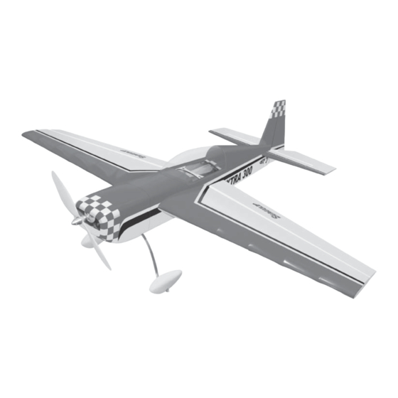
Specifications
Wing Span ------------------------------- 43 in --------------------- 109cm.
Wing Area ------------------------------- 367 sq in ---------- 23.7 sq dm.
Weight ------------------------------------ 20-21 oz ------------ 566-595 g.
Length ------------------------------------ 38.4 in ------------------- 97.5cm.
Radio ------------------------------- 4 channel with 4 sub-micro servos.
Motor size ---------------------------- Park 450 to Park 480 Outrunner.
Need to Complete
Speed Control: 35A to 40A Brushless
Recommended Battery 3-cell 11.1V 1320mAh to 2100mAh Li-Po.
Kit features.
•
Ready-made—minimal assembly & finishing required.
•
Ready-covered covering.
•
Photo-illustrated step-by-step Assembly Manual.
Made in Vietnam.
ASSEMBLY MANUAL
Advertisement
Table of Contents

Related Manuals for Seagull Models Extra 300


Summary of Contents for Seagull Models Extra 300
-
Page 1: Specifications
ASSEMBLY MANUAL Specifications Wing Span ------------------------------- 43 in --------------------- 109cm. Wing Area ------------------------------- 367 sq in ---------- 23.7 sq dm. Weight ------------------------------------ 20-21 oz ------------ 566-595 g. Length ------------------------------------ 38.4 in ------------------- 97.5cm. Radio ------------------------------- 4 channel with 4 sub-micro servos. Motor size ---------------------------- Park 450 to Park 480 Outrunner. -
Page 2: Additional Items Required
ARTF , yet the design allows the aeroplane to be kept light. You will find that most of the work has been done for you already.Flying the EP EXTRA 300 is simply a joy. This instruction manual is designed to help you build a great flying aeroplane. Please read this manual thoroughly before starting assembly of your EP EXTRA 300. -
Page 3: Parts Listing
2mm ball driver. gluing! This will ensure proper as- Phillips head screwdriver. sembly as the EP EXTRA 300 is 220 grit sandpaper. made from natural materials and 90° square or builder’s triangle. minor adjustments may have to be Wire cutters. -
Page 4: Hinging The Ailerons
EXTRA 300. Instruction Manual. HINGING THE AILERONS. T-pin. Note: The control surfaces, including the ailerons, elevators, and rudder, are prehinged with hinges installed, but the hinges are not glued in place. It is imperative that you properly adhere the hinges in place per the steps that follow using a high-quality thin C/A glue. -
Page 5: Hinging The Rudder
www.seagullmodels.com C/A glue. HINGING THE RUDDER. Glue the rudder hinges in place using the same tectniques used to hinge the ailerons. ! 6) Using C/A remover/debonder and a paper towel, remove any excess C/A glue that may have accumulated on the wing or in the aileron hinge area. -
Page 6: Installing The Main Landing Gear
EXTRA 300. Instruction Manual. C/A glue. A drop of C/A glue on the wheel collar screws will help keep them from coming lose during operation. C/A glue. Repeat the process for the other wheel. INSTALLING THE MAIN LANDING GEAR. !1) Using the hardware provided, mount the main landing gear to the fuselage. -
Page 7: Cowling Installation
www.seagullmodels.com Blind nut. Front view. COWLING INSTALLATION. ! 1) Slide the fiberglass cowl over the en- gine and line up the back edge of the cowl with the marks you made on the fuselage then trim and cut. 3x10mm. C/A glue. Motor. - Page 8 EXTRA 300. Instruction Manual. ! 2) While keeping the back edge of the cowl flush with the marks, align the front of the cowl with the crankshaft of the motor. The front of the cowl should be positioned so the crankshaft is in nearly the middle of the cowl opening.
- Page 9 www.seagullmodels.com !4) Using a ruler & pen to draw a straight Using a small weight ( Weighted fuel pick-up ) and thread, feed the string through line as pictures below works well the wing as indicated. Pen. Attach the string to the servo lead and carefully thread it though the wing.
-
Page 10: Installing The Switch
EXTRA 300. Instruction Manual. Left side. Rudder servo. Repeat the procedure for rudder servo. INSTALLING THE SWITCH. Install the switch into the precut hole in the side, in the fuselage. Repeat the procedure for orther wing haft. FUSELAGE SERVO INSTALLATION. -
Page 11: Vertical Stabilizer Installation
www.seagullmodels.com ! 2) Using a modeling knife, carefully remove ! 6) Using a modeling knife, carefully re- the covering at mounting slot of horizontal sta- move the covering that overlaps the stabilizer bilizer ( both side of fuselage). mounting platform sides in the fuselage. Re- move the covering from both the top and the ! 3) Slide the stabilizer into place in the pre- bottom of the platform sides. - Page 12 EXTRA 300. Instruction Manual. ! 2) Slide the vertical stabilizer into the slot in the top of the fuselage. The rear edge of the stabilizer should be flush with the rear edge of the fuselage and the lower rudder hinge should engage the precut hinge slot in the lower fuselage.
-
Page 13: Control Horn Installation
www.seagullmodels.com CONTROL HORN INSTALLATION. Control horn install as same as method of aileron wing. See pictures below. 2x12mm. Rudder servo. Elevator servo. Rudder control horn. MOUNTING THE TAIL WHEEL BRACKET. See pictures below: Elevator control horn. PUSHROD INSTALLATION. Pushrod install as same as method of pushrod wing. - Page 14 EXTRA 300. Instruction Manual. Tie wrap. Expoy glue. Receiver. INSTALLING THE BATTERY-RECEIVER. ATTACHMENT WING-FUSELAGE. See pictures below. Attach the aluminium tube into fuselage. Battery tray M2x8mm. Tie wrap or rubber band. Battery. Insert two wing panels as pictures below:...
-
Page 15: Control Throws
CONTROL THROWS. We highly recommend setting up the EP EXTRA 300 using the control throws listed at right. We have listed control throws for both Low Rate (initial test flying/sport flying) and High Rate (aerobatic flying). -
Page 16: Flight Preparation
!2) Check every bolt and every glue joint in the EP EXTRA 300 to ensure that every- thing is tight and well bonded. !3) Double check the balance of the air- plane.
Need help?
Do you have a question about the Extra 300 and is the answer not in the manual?
Questions and answers