Table of Contents
Advertisement
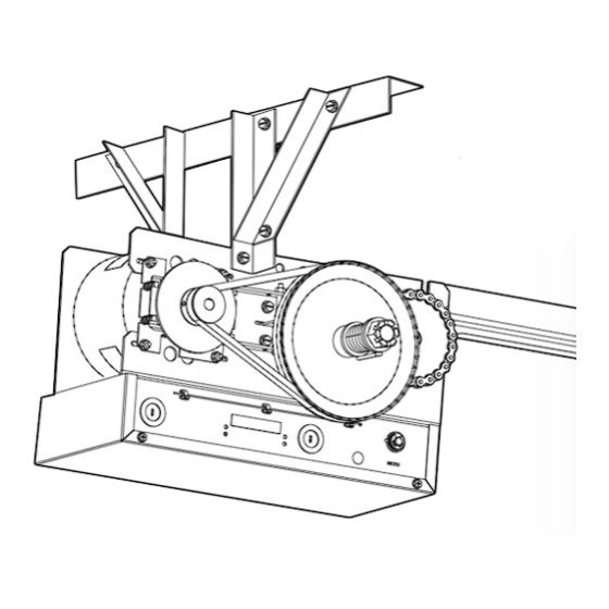
MEDIUM DUTY DOOR OPERATOR
MODELS MT5011U & BMT5011U
INSTALLATION MANUAL
Your model may look different than the model illustrated in this manual.
2 YEAR WARRANTY
Serial #
(located on electrical box cover)
Installation Date
THIS PRODUCT IS TO BE
INSTALLED AND SERVICED BY A
TRAINED DOOR SYSTEMS
TECHNICIAN ONLY.
Visit www.liftmaster.com to locate a
professional installing dealer in your area.
OPERATOR RATING: 12 cycles per hour,
50 cycles per day; maximum
NOT FOR RESIDENTIAL USE
Advertisement
Table of Contents

Related Manuals for Chamberlain MT5011U


Summary of Contents for Chamberlain MT5011U
- Page 1 MEDIUM DUTY DOOR OPERATOR MODELS MT5011U & BMT5011U INSTALLATION MANUAL Your model may look different than the model illustrated in this manual. THIS PRODUCT IS TO BE 2 YEAR WARRANTY INSTALLED AND SERVICED BY A Serial # TRAINED DOOR SYSTEMS (located on electrical box cover) TECHNICIAN ONLY.
-
Page 2: Table Of Contents
TABLE OF CONTENTS SAFETY INFORMATION LOGIC BOARD LAYOUT APPLICATION BASIC PROGRAMMING 20-23 Determine the Wiring Type ....20-21 OPERATOR SPECIFICATIONS Remote Controls ..... . 21-22 CARTON INVENTORY Timer-to-Close (TTC) . -
Page 3: Safety Information
WARNING SAFETY INFORMATION IMPORTANT INSTALLATION INSTRUCTIONS WARNING WARNING To reduce the risk of SEVERE INJURY or DEATH: 1. READ AND FOLLOW ALL INSTALLATION WARNINGS AND 8. Install control station: INSTRUCTIONS. • within sight of the door. 2. Install door operator ONLY on properly balanced and •... -
Page 4: Operator Specifications
OPERATING TEMPERATURE: ....-4˚ F to + 122˚ F FINISH: ....Powder coated, Corrosion Resistant Steel (-20˚ C to + 50˚ C) UL Listed to 40˚ C: Chamberlain tested to 50˚ C... -
Page 5: Carton Inventory
CARTON INVENTORY Before beginning your installation check that all components were provided. C L O NOTE: The tracks are shipped separately. Actual track length will exceed door height by 2 feet. EXAMPLE: The track for 12 foot door will S T O be 14 feet. -
Page 6: Assembly
ASSEMBLY Install track spacers. Position the track spacers evenly over the length of the track using the pre-punched holes. Header End Flange Hex Nut Bolt Track Spacers 3/8" - 16 x 3/4" Track Bolt 3/8" - 16 x 3/4" Flange Hex Nut Operator End Install front idler. - Page 7 ASSEMBLY Slide trolley onto the track. Track Operator End Trolley Attach track to operator. Flange Hex Nut Track Header End Flange Hex Bolt 3/8" - 16 x 3/4" Bolt 3/8" - 16 x 3/4" Flange Hex Operator Bolt 3/8" - 16 x 3/4" Bolt 3/8"...
- Page 8 ASSEMBLY Attach chain to front of trolley. Wrap chain around front idler in the direction shown. Track Chain Front Idler Trolley Master Link Slide trolley 2 inches away Chain from front idler. 2" Operator Trolley Drive Sprocket Inner Nut Chain Master Link Wrap chain around drive sprocket.
-
Page 9: Typical Installation
TYPICAL INSTALLATION INSTALL THE HEADER BRACKET WARNING WARNING To prevent possible SERIOUS INJURY or DEATH: • Header bracket MUST be RIGIDLY fastened to structural • NEVER try to loosen, move or adjust door, springs, cables, CAUTION support on header wall or ceiling, otherwise door might not pulleys, brackets, or their hardware, ALL of which are under reverse when required. -
Page 10: Install The Operator
TYPICAL INSTALLATION WARNING INSTALL THE OPERATOR CAUTION CAUTION To avoid possible SERIOUS INJURY from a falling operator: • Fasten the operator SECURELY to structural supports of the • Concrete anchors MUST be used if installing ANY brackets into building. masonry. Swing the operator to a horizontal position and temporarily Align holes in track with holes in header bracket and secure secure with rope, chain or support from fl... -
Page 11: Power And Ground Wiring Connections
TYPICAL INSTALLATION INSTALL THE OPERATOR Attach the door arms to the trolley and door bracket. Make Use appropriate hardware to secure door bracket to door sure the open side of the notch on the door arm faces the (not provided). NOTE: When properly installed and adjusted the door. -
Page 12: Install 3-Button Control Station
TYPICAL INSTALLATION POWER AND GROUND WIRING CONNECTIONS Run power wires to electrical box according to national and Remove cover. local electrical codes. Conduit Attach power and ground wires to high voltage terminal strip. Power Control Line Power 115 Vac Single Phase WARNING INSTALL 3-BUTTON CONTROL STATION WARNING... -
Page 13: Setup Radio Antenna
TYPICAL INSTALLATION INSTALL 3-BUTTON CONTROL STATION Connect wires to the control station and replace the control Fasten the entrapment warning placard next to the control station. station cover. Power Entrapment Placard AUX ANT ^^^^ AUX ANT AUX ANT LEARN STOP CLOSE OPEN LMEP1 LMEP2 COM INTRLK STOP CLOSE... -
Page 14: Important Safety Instructions
TYPICAL INSTALLATION SETUP RADIO ANTENNA OPTION B Attach the antenna to the electrical box using the wire tie Locate the wire antenna on the outside of the electrical box. holes. Bend antenna across the front of the electrical box, Cut wire ties and discard standoff. ensuring that the antenna is 4 inches away from the front of the electrical box. -
Page 15: Adjustment
ADJUSTMENT WARNING ADJUST THE LIMITS WARNING WARNING To avoid SERIOUS personal INJURY or DEATH from • Disconnect electric power BEFORE performing ANY adjustments electrocution: or maintenance. Depress retaining plate. Adjust CLOSE limit. Adjust OPEN limit. Retaining Plate OPEN Limit Nut OPEN Limit Switch Decrease Door Increase Door... -
Page 16: Liftmaster Monitored Entrapment Protection (Lmep)
ENTRAPMENT PROTECTION WARNING WARNING LIFTMASTER MONITORED ENTRAPMENT CAUTION WARNING WARNING PROTECTION (LMEP) To prevent possible SERIOUS INJURY or DEATH from a closing IMPORTANT INFORMATION ABOUT THE LIFTMASTER door: MONITORED ENTRAPMENT PROTECTION DEVICES • Be sure power is not connected to the door operator BEFORE A LiftMaster Monitored Entrapment Protection (LMEP) device installing the photoelectric sensor. -
Page 17: Entrapment Protection
ENTRAPMENT PROTECTION INSTALL THE PHOTOELECTRIC SENSORS The following instructions show recommended assembly of the bracket(s) and “C” wrap based on the wall installation of the photoelectric sensors on each side of the door or on the door tracks themselves. There are also alternate mounting methods which may fi t your installation requirements better. -
Page 18: Mount The Photoelectric Sensors
ENTRAPMENT PROTECTION MOUNT THE PHOTOELECTRIC SENSORS Center each sensor in the bracket with the lenses pointing toward each other across the door. Wing Nut “C” Wrap Wire Attach the sensors to the brackets with the provided hardware. Finger tighten the receiving sensor wing nut. Securely tighten Indicator Light the sending sensor wing nut. -
Page 19: Logic Board Layout
ENTRAPMENT PROTECTION ENTRAPMENT PROTECTION WIRING OPTIONS ALTERNATE INSTALLATIONS: CPS-U PHOTOELECTRIC SENSOR WITH 2-WIRE SENSING EDGE 2-wire electric or pneumatic sensing edge (White) (White/Black) CPS-U PHOTOELECTRIC SENSOR WITH 4-WIRE SENSING EDGE 4-wire electric sensing edge (White/Black) (White) 2-WIRE ELECTRIC OR PNEUMATIC SENSING EDGE (B2 NOT AVAILABLE) 2-wire electric or pneumatic sensing edge (White/Black) (White) -
Page 20: Basic Programming
BASIC PROGRAMMING DETERMINE THE WIRING TYPE The functionality of this operator is based on the wiring type. The operator is shipped from the factory in standard C2 wiring type (factory default). LIFTMASTER MONITORED ENTRAPMENT PROTECTION (LMEP) DEVICE IS RECOMMENDED. A LiftMaster Entrapment Protection (LMEP) device is required for any momentary contact to close mode of operation including B2, TTC and remote controls. -
Page 21: Remote Controls
BASIC PROGRAMMING DETERMINE THE WIRING TYPE ALTERNATE INSTALLATION: C2 WIRING TYPE WITH MONITORED ALTERNATE INSTALLATION: C2 WIRING TYPE WITHOUT ENTRAPMENT PROTECTION DEVICE MONITORED ENTRAPMENT PROTECTION DEVICE (FACTORY DEFAULT) • Momentary contact to open and stop with constant pressure to • Momentary contact to open and stop with constant pressure to close. -
Page 22: Timer-To-Close (Ttc)
BASIC PROGRAMMING REMOTE CONTROLS WARNING WARNING To prevent possible SEVERE INJURY or DEATH: • Activate door ONLY when it can be seen clearly, is properly • Install a LiftMaster Monitored Entrapment Protection (LMEP) CAUTION adjusted and there are no obstructions to door travel. device. -
Page 23: Testing
BASIC PROGRAMMING TIMER-TO-CLOSE (TTC) CLEAR THE TIMER-TO-CLOSE (TTC) TIMER DEFEAT The TTC can be temporarily disabled Release the Press and hold TTC button by pressing a STOP button. the TTC button (LED will go for 6 seconds. Press and out). The TTC TTC will become enabled after the release the will no longer... -
Page 24: Emergency Disconnect
EMERGENCY DISCONNECT WARNING WARNING To prevent possible SERIOUS INJURY or DEATH from a falling door or arm: CAUTION • DO NOT stand under the door arm when pulling the emergency • NEVER use emergency release handle unless doorway is clear release. -
Page 25: Troubleshooting
TROUBLESHOOTING Technical Support 1-800-528-2806 CONDITION POSSIBLE CAUSE OPERATOR WILL NOT ➤ Verify primary line voltage (120 Vac, 60 Hz) is present at terminals L1 & L2. RESPOND TO ANY A) No power The LED will fl ash when power is present. COMMANDS ➤... -
Page 26: Diagram
TROUBLESHOOTING The status of the operator can be determined by counting the number of fl ashes of the LED on the logic board. DIAGNOSTIC LED TABLE # OF LED FLASHES STATUS System OK. Operating in C2 mode None System OK. Operating in B2 mode None Stuck CLOSE button Check for stuck close button or shorted close wire... -
Page 27: Accessories
ACCESSORIES ENTRAPMENT PROTECTION DEVICES REMOTE CONTROLS 315 MHZ CPS-UN4 LiftMaster offers a variety of SECURITY✚ ® Remote Commercial Protector System: Controls for your application needs. Single to 4-Button, LiftMaster Monitored Entrapment Protection (LMEP) visor or key chain. Contact your authorized dealer. provides protection on doors up to 45' wide. -
Page 28: Control Connection Diagram
DEVICE TO REVERSE EXTERNAL INTERLOCK Note: For photoelectric sensors connection options see Remove Factory Installed Jumper ENTRAPMENT PROTECTION section. When Interlock is Used Sensing Device 2 OR MORE All Wiring Types © 2011, The Chamberlain Group, Inc. 01-34005E All Rights Reserved...
Need help?
Do you have a question about the MT5011U and is the answer not in the manual?
Questions and answers