Table of Contents
Advertisement
www.nordictrack.com
Model No. NTL19814.0
Serial No.
Write the serial number in the space
above for reference.
Serial Number
Decal
ACTIVATE YOUR
WARRANTY
To register your product and
activate your warranty today, go
to www.nordictrackservice.com/
registration.
CUSTOMER CARE
For service at any time, go to
www.nordictrackservice.com.
Or call 1-800-TO-BE-FIT
(1-800-862-3348)
Mon.–Fri. 6 a.m.–6 p.m. MT
Sat. 8 a.m.–12 p.m. MT
Please do not contact the store.
CAUTION
Read all precautions and instruc-
tions in this manual before using
this equipment. Save this manual
for future reference.
USER'S MANUAL
990
Advertisement
Table of Contents

Related Manuals for NordicTrack C 990


Summary of Contents for NordicTrack C 990
- Page 1 Model No. NTL19814.0 USER’S MANUAL Serial No. Write the serial number in the space above for reference. Serial Number Decal ACTIVATE YOUR WARRANTY To register your product and activate your warranty today, go to www.nordictrackservice.com/ registration. CUSTOMER CARE For service at any time, go to www.nordictrackservice.com.
-
Page 2: Table Of Contents
Note: The decals may not be shown at actual size. 305284 The BLUETOOTH word mark and logos are registered trademarks of ® Bluetooth SIG, Inc. and are used under license. Google Maps is a trademark of Google Inc. NORDICTRACK is a registered trademark of ICON Health & Fitness, Inc. -
Page 3: Important Precautions
20. To purchase a surge suppressor, see your local 4. The treadmill is intended for home use only. NORDICTRACK dealer, call the telephone Do not use the treadmill in any commercial, number on the front cover of this manual, or rental, or institutional setting. - Page 4 20. Keep fingers, hair, and clothing away from 26. Never insert any object into any opening on the moving walking belt. the treadmill. 21. The treadmill is capable of high speeds. 27. Inspect and properly tighten all parts of the Adjust the speed in small increments to treadmill regularly.
- Page 6 STANDARD SERVICE PLANS...
-
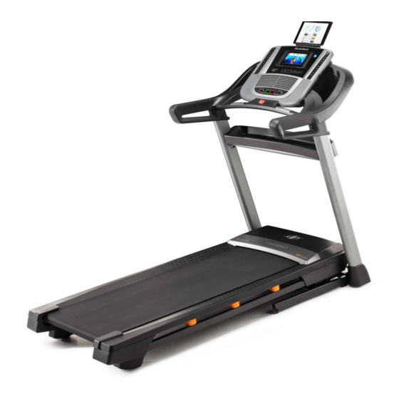
Page 7: Before You Begin
Thank you for selecting the revolutionary reading this manual, please see the front cover of this NORDICTRACK C 990 treadmill. The C 990 treadmill manual. To help us assist you, please note the product ® offers an impressive selection of features designed model number and serial number before contacting us. -
Page 8: Part Identification Chart
PART IDENTIFICATION CHART Use the drawings below to identify small parts used for assembly. The number in parentheses below each draw- ing is the key number of the part, from the PART LIST near the end of this manual. The number following the key number is the quantity used for assembly. -
Page 9: Assembly
ASSEMBLY • Assembly requires two persons. • To identify small parts, see page 8. • Place all parts in a cleared area and remove the • Assembly requires the following tools: packing materials. Do not dispose of the packing the included hex key materials until you finish all assembly steps. - Page 10 2. Make sure that the power cord is unplugged. Wire Press a Base Cap (74) into each side of the Base (94). Next, remove the tie securing the Upright Wire (81) to the front of the Base (94). Identify the Right Upright (90). Have a second person hold the Right Upright near the Base (94).
- Page 11 4. Insert a Wheel Spacer (63) into a Front Wheel (62). Hold the Front Wheel inside the bottom of the Right Upright (90), and insert a 3/8" x 4" Screw (7) with a 3/8" Star Washer (13) into the Right Upright and the Front Wheel. Repeat this step on the left side of the tread- mill (not shown).
-
Page 12: 3/4" Screws (4
6. Remove and save the four indicated 5/16" x 3/4" Screws (4). Identify the Left and Right Base Covers (82, 83). Slide the Left Base Cover onto the Left Upright (89), and slide the Right Base Cover onto the Right Upright (90). Do not press the Base Covers into place yet. - Page 13 8. Insert the Upright Wire (81) into the bottom of the right handrail assembly (D) and out of the end as shown. Attach the right handrail assembly (D) to the Right Upright (90) with two 5/16" x 2 1/2" Screws (28) and two 5/16"...
-
Page 14: 3/4" Screws (4
10. Set the Console Base (64) face down on a soft surface to avoid scratching the Console Base. If there are ties securing the Pulse Crossbar (93) to the Console Base, remove the ties. Remove and discard the four indicated screws (E). - Page 15 12. IMPORTANT: To avoid damaging the Pulse Crossbar (93), do not use power tools and do not overtighten the #10 x 3/4" Screws (9). Orient the Pulse Crossbar (93) as shown. Attach the Pulse Crossbar to the Handrails (86) with two #10 x 3/4"...
-
Page 16: 3/4" Screws (4
14. Set the console assembly on the brackets on the Handrails (86). Make sure not to pinch any Console wires. Assembly Attach the console assembly with the four 5/16" x 3/4" Screws (4) that you removed in step 10 and four 5/16" Star Washers (11); do not fully tighten the Screws yet. - Page 17 17. Attach the Tray (73) to the Upright Crossbar (41) with four #8 x 3/4" Screws (2); start all four Screws, and then tighten them. 18. Firmly tighten the six 3/8" x 4" Screws (7) (only one side is shown). Then, press the Left Base Cover (82) and the Right Base Cover (83) onto the Base (94).
-
Page 18: 3/4" Screws (4
19. Note: If you assemble the treadmill on a smooth surface, it may roll forward during this step. Raise the Frame (56) to the upright position. Brackets Have a second person hold the Frame until step 21 is completed. Remove the two 5/16" x 3/4" Screws (4) from the Latch Crossbar (38). - Page 19 21. Remove the 5/16" Nut (12) and the 5/16" x 2 1/4" Bolt (3) from the bracket on the Latch Crossbar (38). Align the upper end of the Storage Latch (53) with the bracket on the Latch Crossbar (38), and insert the 5/16" x 2 1/4" Bolt (3) through the bracket and the Storage Latch.
-
Page 20: How To Use The Treadmill
HOW TO USE THE TREADMILL HOW TO CONNECT THE POWER CORD nominal 120-volt circuit capable of carrying 15 or more amps. To avoid overloading the circuit, do Use a Surge Suppressor not plug other electrical devices, except for low- power devices such as cell phone chargers, into Your treadmill, like other electronic equipment, can be the surge suppressor or into an outlet on the same circuit. - Page 21 CONSOLE DIAGRAM FEATURES OF THE CONSOLE You can even listen to your favorite workout music or audio books with the console’s sound system while you The treadmill console offers an impressive array of exercise. features designed to make your workouts more effec- tive and enjoyable.
- Page 22 HOW TO TURN ON THE POWER HOW TO USE THE MANUAL MODE IMPORTANT: If the treadmill has been exposed to 1. Insert the key into the console. cold temperatures, allow it to warm to room tem- perature before you turn on the power. If you do See HOW TO TURN ON THE POWER at the left.
- Page 23 4. Change the incline of the treadmill as desired. The My Trail tab will show a track that represents 1/4 mile (400 m). As you exercise, the flashing To change the incline of the treadmill, press the rectangle will show your progress. The My Trail tab Incline increase and decrease buttons or one of the will also show the number of laps you complete.
- Page 24 6. Measure your heart rate if desired. 8. When you are finished exercising, remove the key from the console. You can measure your heart rate using either the handgrip heart rate monitor or an optional Step onto the foot rails, press the Stop button, and chest heart rate monitor (see page 28 for infor- adjust the incline of the treadmill to zero.
- Page 25 4. Follow your progress with the displays. During the workout, the profiles on the See step 5 on page 23. If you select an onboard speed and workout, the display will show the time remaining incline tabs instead of the elapsed time. Current Segment will show your progress.
- Page 26 3. Select a pulse workout. The workout will continue until you reach the goal that you set. The walking belt will then slow to a stop. To select a pulse workout, press the Heart Rate button repeatedly until the desired workout appears Note: The calorie goal is an estimate of the in the display.
- Page 27 HOW TO USE AN IFIT WORKOUT 5. Start the workout. Note: To use an iFit workout, you must have access See step 3 on page 24. to a wireless network (see pages 28 to 31). An iFit account is also required. Go to www.iFit.com to reg- During some workouts, an audio coach may guide ister for an iFit account.
-
Page 28: To Change Console Settings
HOW TO USE THE SOUND SYSTEM HOW TO CHANGE CONSOLE SETTINGS To play music or audio books through the console The console features a settings mode that allows you sound system while you exercise, plug a 3.5 mm male to view usage information, to personalize console set- to 3.5 mm male audio cable (not included) into the jack tings, and to set up and manage a wireless network on the console and into a jack on your MP3 player,... - Page 29 Units—The selected unit of measurement will The WiFi–Advanced option will allow you to set up appear in the matrix. To change the unit of mea- a wireless network connection using your com- surement, press the Enter button. To view distance puter, smart phone, tablet, or other Wi-Fi device.
- Page 30 5. Use WiFi–Advanced to set up a wireless A list of networks will appear in the matrix. Press the up and down buttons to highlight the desired connection. network. Then, press the Enter button. Note: Do not select IFIT_SETUP. This option will allow you to set up a wireless network connection using your computer, smart Note: The time display will show the number of phone, tablet, or other Wi-Fi device.
-
Page 31: To Adjust Cushioning System
HOW TO ADJUST THE CUSHIONING SYSTEM HOW TO USE THE TABLET HOLDER Remove the key from the console and unplug the You can use your tablet to browse media while you power cord. In order to adjust the cushions, you may exercise. -
Page 32: How To Fold And Move The Treadmill
HOW TO FOLD AND MOVE THE TREADMILL HOW TO FOLD THE TREADMILL HOW TO MOVE THE TREADMILL To avoid damaging the treadmill, adjust the incline Before moving the treadmill, fold it as described at the to zero before you fold the treadmill. Then, remove left. -
Page 33: Maintenance And Troubleshooting
MAINTENANCE AND TROUBLESHOOTING MAINTENANCE SYMPTOM: The power turns off during use Regularly clean the treadmill and keep the walking a. Check the power switch (see drawing c at the left). belt clean and dry. First, press the power switch into If the switch has tripped, wait for five minutes and the off position and unplug the power cord. - Page 34 Locate the Reed Switch (52) and the Magnet (50) b. If the walking belt is overtightened, treadmill per- on the left side of the Pulley (49). Turn the Pulley formance may decrease and the walking belt may until the Magnet is aligned with the Reed Switch. become damaged.
- Page 35 SYMPTOM: The walking belt is off-center or slips SYMPTOM: The iFit mode does not function when walked on correctly a. If the walking belt is off-center, first remove the a. If the iFit mode is not functioning correctly, make key and UNPLUG THE POWER CORD. If the sure that the treadmill has the most current firm- walking belt has shifted to the left, use the hex ware available (see step 3 on page 29).
-
Page 36: Exercise Guidelines
EXERCISE GUIDELINES Burning Fat—To burn fat effectively, you must exer- WARNING: cise at a low intensity level for a sustained period of Before beginning this time. During the first few minutes of exercise, your or any exercise program, consult your physi- body uses carbohydrate calories for energy. - Page 37 SUGGESTED STRETCHES The correct form for several basic stretches is shown at the right. Move slowly as you stretch —never bounce. 1. Toe Touch Stretch Stand with your knees bent slightly and slowly bend forward from your hips. Allow your back and shoulders to relax as you reach down toward your toes as far as possible.
-
Page 38: Part List
PART LIST Model No. NTL19814.0 R1114A Key No. Qty. Description Key No. Qty. Description #8 x 1/2" Screw Magnet #8 x 3/4" Screw Reed Switch Clip 5/16" x 2 1/4" Bolt Reed Switch 5/16" x 3/4" Screw Storage Latch #10 Star Washer Drive Motor 5/16"... - Page 39 PART LIST Model No. NTL19814.0 R1114A Key No. Qty. Description Key No. Qty. Description Right Frame Cover #8 x 1 3/4" Screw Left Foot Pad Bracket Clip Right foot Pad Electronics Bracket Hood Post – User’s Manual Note: Specifications are subject to change without notice. For information about ordering replacement parts, see the back cover of this manual.
-
Page 40: Exploded Drawing
EXPLODED DRAWING A Model No. NTL19814.0 R1114A... - Page 41 EXPLODED DRAWING B Model No. NTL19814.0 R1114A...
- Page 42 EXPLODED DRAWING C Model No. NTL19814.0 R1114A...
- Page 43 EXPLODED DRAWING D Model No. NTL19814.0 R1114A...
-
Page 44: Ordering Replacement Parts
ORDERING REPLACEMENT PARTS To order replacement parts, please see the front cover of this manual. To help us assist you, be prepared to provide the following information when contacting us: • the model number and serial number of the product (see the front cover of this manual) •...
Need help?
Do you have a question about the C 990 and is the answer not in the manual?
Questions and answers