Table of Contents
Advertisement
Advertisement
Table of Contents

Related Manuals for Hunt Electronic HLC-1NCF


Summary of Contents for Hunt Electronic HLC-1NCF
-
Page 1: User Manual
User Manual INDOOR DOME IP CAMERA... - Page 2 WARNING TO REDUCE THE RISK OF FIRE OR ELECTRIC SHOCK, DO NOT EXPOSE THIS PRODUCT TO RAIN OR MISTURE. DO NOT INSERT ANY METALLIC OBJECT THROUGH VENTILATION GRILLS. CAUTION CAUTION RISK OF ELECTRIC SHOCK DO NOT OPEN CAUTION:TO REDUCE THE RISK OF ELECTRIC SHOCK. DO NOT REMOVE COVER (OR BACK).
-
Page 3: Table Of Contents
Content I. PREFACE ........................ 4 II. PRODUCT SPECIFICATIONS ................4 III. PRODUCT INSTALLATION ................... 7 A. M ....................7 ONITOR ETTINGS B. H ..................8 ARDWARE NSTALLATION C. IP A ....................12 SSIGNMENT D. I ................... 16 NSTALL CTIVE CONTROL IV. -
Page 4: Preface
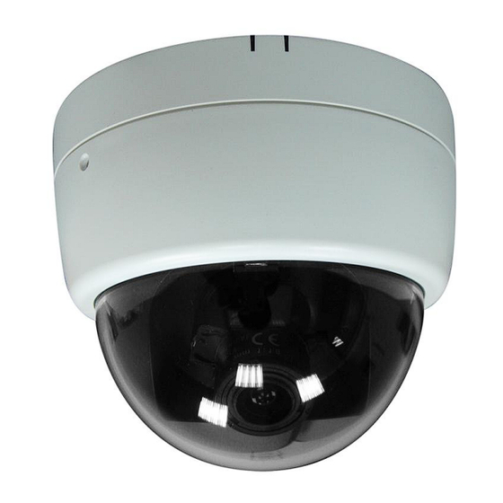
I. Preface This is a 1/3.2” CMOS sensor IP camera with a built-in web server. The user can view real-time video via IE browser. It supports H.264, and M-JPEG video compression, providing smooth and high video quality. The video can be stored in a SD card and playback remotely. - Page 5 256MB Flash 16MB 1/3.2” Megapixel CMOS sensor Image sensor Sensitivity B / W: 0.1 Lux (AGC ON) Lens Type Vari-focal Lens 3-9mm@F1.8 27.31° ~ 75.24° (H) Angle of View 19.09° ~ 54.16° (V) Mechanism IR cut Filter (Optional) Built-in 18 IR LED IR Distance 15M DI / DO Video output...
- Page 6 320x240@30fps, 176x144@30fps Brightness, Contrast, Hue, Saturation, Sharpness, Shutter Speed adjustable, AGC, Video Adjust Sense-Up, D-WDR, Flip, Mirror, Noise reduction, Day&Night adjustable, White Balance Triple Streaming Image snapshot Full screen monitoring Privacy Mask Yes, 3 different areas Compression format H.264/ M-JPEG/ MPEG4(3GPP only) Video bitrates adjust CBR, VBR Motion Detection...
-
Page 7: Product Installation
III. Product Installation A. Monitor Settings Right-Click on the desktop. Select “ Properties” Change color quality to highest (32bit). -
Page 8: Hardware Installation
B. Hardware Installation... - Page 9 1. Dome Installation Steps a. Use screws to lock the bottom of camera to the ceiling or the wall. b. Use 3-Axis to adjust the lens angle. c. Close the dome cover. d. Tighten the screw on the cover to fix it. 2.
- Page 10 3. Connector Instruction The camera connectors are as below. Connect the power and the Ethernet cable with the camera, and set it according to your network environment.
- Page 11 4. PoE (Power Over Ethernet) (Optional) 802.3af, 15.4W PoE Switch is recommended Power over Ethernet (PoE) is a technology that integrates power into a standard LAN infrastructure. It enables power to be provided to a network device, such as an IP phone or a network camera, using the same cable as that used for network connection.
-
Page 12: Ip Assignment
C. IP Assignment Use the software, “IP Installer” to assign the IP address of IP CAMERA. The software is in the attached software CD. IP installer supports two languages: IPInstallerCht.exe:Chinese version IPInstallerEng.exe:English version iii. There are 3 kinds of IP configuration. Fixed IP (Public IP or Virtual IP) DHCP (Dynamic IP) Dial-up (PPPoE) - Page 13 IP Installer configuration: vii. IP Installer will search all IP Cameras connected on LAN. The user can click “Search Device” to search again. viii. Click one of the IP Camera listed on the left side. The network configuration of this IP camera will show on the right side. You may change the “name”...
- Page 14 The same Subnet: IP CAM IP address: 192.168.1.200 PC IP address: 192.168.1.100 Different Subnets: IP CAM IP address: 192.168.2.200 PC IP address: 192.168.1.100 To Change the PC IP address: Control PanelNetwork ConnectionsLocal Area Connection PropertiesInternet Protocol (TCP/IP) Properties Please to make sure your IP Camera and PC have the same Subnet. If not, please change IP Camera subnet or PC IP subnet accordingly.
- Page 15 Then, please key in the default “user name: admin” and “password: admin”.
-
Page 16: Install Active Xcontrol
D. Install ActiveX control 1. For users of IE 6.0 or above: For the first time to view the camera video via IE, it will ask you to install the ActiveX component. 1. If the installation failed, please check the security setting for the IE browser. IE ... - Page 18 When popup the following dialogue box, click “Yes”. 2. You can choose another way: Go to: IE→Tools → Internet Options… → Security Tab → Trusted sites → Add the IP address and click "OK". In the site list you can key one single IP address or a LAN address. For example, if you add "192.168.21.*", all the IP address under .21 LAN will be regarded as trusted sites.
- Page 19 2. To Non-IE Web Browser Users If you use Firefox or Google chrome to access the IP camera but fail to watch the live video, please follow the steps to install necessary tools: (The following pictures are based on chrome.) a.
- Page 20 In the pop-up window, please tick the first and the third file as the picture below. Click "Next" to download both "Microsoft .NET Framework 4 Client Profile (Web Installer)" and "Microsoft Visual C++ 2010 Redistributable Package (x64)". After finishing downloading, execute the two files respectively to install them. The windows may ask you to reboot the PC when the installation is finished.
- Page 21 After finishing the downloading, execute the files to install ActiveX. Then restart the browser. c. If you execute the steps above but still cannot see the live video normally, please try the following solution: Search for the file "np_hoem_x.dll" in your system disk. For Windows XP users, please go to "Start"...
- Page 22 install the latest ActiveX control. Start your web browser, and repeat the step 2-b: "Download the installation program which does not support IE browser" to download and install ActiveX.
-
Page 23: Live Video
IV. Live Video Start an IE browser, type the IP address of the IP camera in the address field. It will show the following dialogue box. Key-in the user name and password. The default user name and password are “admin” and “admin”. When the IP Camera is connected successfully, it shows the following program interface. - Page 24 1. Get into the administration page. 2. Video Snapshot. 3. Show the system time, video resolution, and video refreshing rate. 4. Adjust image: 1/2x, 1x, 2x. 5. Selects the video streaming source: If the streaming 2 is closed, this function will not be displayed. 6.
- Page 25 II. Record Start: Record the video in the local PC. It will ask where to save the video. To stop recording, right-click again. Select “Record Stop”. The video format is AVI. Use Microsoft Media Player to play the recorded file. III.
-
Page 26: Camera Configuration
V. Camera Configuration Click to get into the administration page. Click to go back to the live video page. -
Page 27: System
A. System I. System Information Server Information: Set up the camera name, select language, and set up the camera time. Server Name: This is the Camera name. This name will be shown on the IP Installer. Select language: English, Traditional Chinese, and Simplified Chinese can be selected. - Page 28 Server time setting: Select options to set up time - “NTP”, “Synchronize with PC’s time”, “Manual”, “The date and time remain the same”.
- Page 29 II. User Management The IP Camera supports three different users, administrator, general user, and anonymous user. a. Anonymous User Login: Select “Yes” for allowing everybody to watch live video without username and password. However, if you try to enter the configuration page the camera will ask you to key-in username and password.
- Page 30 c. Add user Type the user name and password, then click “Add/Set”. The guest user can only browse live video page and is not allowed to enter the configuration page. d. Click “edit” or “delete” in the user list to modify them. The system will ask you to key-in the password in the pop-up window before you edit the user information.
- Page 31 To update the firmware online, click “Browse…” to select the firmware. Then click “Upgrade” to proceed. Reboot system: re-start the IP camera Factory default: delete all the settings in this IP camera. Setting Management: The user may download the current settings to PC, or upgrade from previous saved settings.
-
Page 32: Network
B. Network I. IP Settings IP Assignment The IP Camera supports DHCP and static IP. DHCP: The IP Camera will get all the network parameters automatically. Static IP: Type-in the IP address subnet mask, gateway, and DNS manually. - Page 33 IPv6 Assignment You can manually key in IPv6 address, enable DHCPv6, and use automatically generated IPv6 address simultaneously. Manually setup the IPv6 address: Key in Address, Gateway, and DNS. DHCPv6: If you have a DHCPv6 server, enable it to assign the IPv6 automatically.
- Page 34 Port Assignment: The user may need to assign different port to avoid conflicts when setting up the IP. Web Page Port: setup web page connecting port and video transmitting port (Default: 80) HTTPs Port: setup the https port(Default: 443) UPnP This IP camera supports UPnP, if this service is enabled on your computer, the camera will automatically be detected and a new icon will be added to “My Network Places.”...
- Page 35 Note: UPnP must be enabled on your computer. Please follow the procedure to activate UPnP: <Approach 1> open the Control Panel from the Start Menu Select Add/Remove Programs Select Add/Remove Windows Components and open Networking Services section Click Details and select UPnP to setup the service The IP device icon will be added to “MY Network Places”...
- Page 36 4. Now the IP device is displayed under the LAN. Double-click the icon to access the camera via web browser. T o disable the UPnP , click "Hide icons for networked UPnP devises" in the tasks column.
- Page 37 RTSP setting If you have a media player that supports RTSP protocol, you can use it to receive the video streaming from IP camera. The RTSP address can be set for two streamings respectively. Please jump to RTSP Server: enable or disable "Disable"...
- Page 38 Multicast Setting (Based on the RTSP Server) Multicast is a bandwidth conservation technology. This function allows several users to share the same packet sent from the IP camera. For using Multicast, appoint here an IP Address and port. TTL means the life time of packet, the larger the value is, the more users can receive the packet.
- Page 39 1. Choose your ONVIF version and settings. Under ONVIF connection, the video will be transmitted by RTSP . Be sure to enable the RTSP server in IP setting, otherwise the IP Cameras will not be able to receive the video via ONVIF . 2.
- Page 40 The web browser "Safari" also has a Bonjour function. Tick "Include Bonjour" in the bookmark setting, for the IP camera to appear under the bonjour category. Click the icon to connect to the IP camera. So far the Bonjour function on Safari browser doesn't support HTTPS protocol.
- Page 41 If your PC supports LLTD, enable this function for allowing checking the connection status, properties, and device location (IP address) in the network map. If the computer is running Windows Vista or Windows 7, you can find LLTD through the path: Control Panel →...
- Page 42 You can select the connection type. • Http: the user can access the camera via the Http path but cannot access it via the Https path. • Https: the user can access the camera via the Https path but cannot access it via the Http path. •...
- Page 43 Certificate generation process: Remove the existing certificate: Before you generate a new certificate, please remove the installed one. Select "Http" connection type and click "Remove". If a dialog box pops up to ask you to confirm, click “Yes”. Created Request: Fill-in the following form and click “apply”.
- Page 44 After generating a certificate request, if you choose to turn it and verified by a trusted third-party, click “Content” and copy all the request content. According to the certificate source, there are two ways to install the certificate: If you had sent the certificate request for signing and receiving a signed certificate, click ”...
- Page 45 If you choose to generate a self-signed certificate, fill-in the following forms and set the validity day, click “Apply” to finish installed it. After finishing the installation, you can click “Content” to call out and check the certificate content. To use Https to access the camera, open your browser, and key-in "https:// (IP address)/"...
- Page 46 Meaning that certificate is self-signed or signed by a Click “Proceed anyway” distrusted institution. continuing to the camera page. b. SNMP (Simple Network Management Protocol) 1. Enable SNMPv1 or SNMPv2 and write the name of both Write Community and Read Community. 2.
- Page 47 3. Enable SNMPv1/SNMPv2 Trap for detecting the Trap server. Please set what event needs to be detected. • Cold Start: The camera starts up or reboots. • Setting changed: The SNMP settings has been changed. • Network Disconnected: The network connection was broken down.
- Page 48 community) • SD Insert / Remove: A Micro SD card is inserted or removed. c. Access list: ”Enable IP address filter” for setting the IP addresses which allows or denies this camera. There are two options, single and range. QoS/DSCP(Quality Server/Differentiated Services Code-point):...
- Page 49 DSCP specifies a simple mechanism for classifying and managing network traffic and provide QoS on IP networks. DSCP is a 6-bit in the IP header for packet classification purpose. Please define it for Live Stream, Event / Alarm and Management. IEEE 802.1x: IEEE 802.1x is an IEEE standard for port-based Network Access Control.
- Page 50 related certificates. III. PPPoE & DDNS: PPPoE: Select “Enabled” to use PPPoE. Key-in Username and password for ADSL connection. Send mail after dialed: When connect to the internet, it will send a mail to a specific mail account. For mail setting, please refer to “Mail and FTP”...
- Page 51 DDNS: It supports DDNS (Dynamic DNS) service. DynDNS: (1) Enable this service (2) Key-in the DynDNS server name, user name, and password. (3) Set up the IP Schedule update refreshing rate. (4) Click “Apply”...
- Page 52 (5) If the schedule update is too frequently, the IP may be blocked. In general, schedule update every day (1440 minutes) is recommended Camddns service: Please enable this service Key-in user name. IP schedule update default at 5 minutes Click “Apply”. DDNS Status (1) Updating: Information update...
- Page 53 (2) Idle: Stop service (3) DDNS registration successful, http://<username>.ddns.camddns.com: Register successfully. (4) Update Failed, the name is already registered: The user name has already been used. Please change it. (5) Update Failed; please check your internet connection: Network connection failed. (6) Update Failed, please check the account information you provided: The server, user name, and password may be wrong.
- Page 54 To send out the video via mail of FTP, please set up the configuration first.
- Page 55 Samba Select this option to send the media files via a neighbor network when an event is triggered. Click “Apply” to save the setting, then use “Test” button to test the server connection. A message box will tell you “OK!” if it works, and a test document will be created in the location.
-
Page 56: A/V Setting
C. A/V Setting... - Page 57 1. Image Setting For security and privacy purposes, there are three areas that can be set up for privacy. Click the Area button first, and then drag an area on the above image. Remember to save your settings. The masked area will not shown on both live view and recording image.
- Page 58 1/50 1/10000 ~ 1/50 1/60 1/10000 ~ 1/60 1/100 1/10000 ~ 1/100 1/125 1/10000 ~ 1/125 1/250 1/10000 ~ 1/250 1/500 1/10000 ~ 1/500 1/1000 1/10000 ~ 1/1000 1/10000 1/10000 * Sense-up options: 1/30, 1/15, 1/10 D. Sense up: When enabled, provides a higher sensitivity in low light conditions by slowing the shutter speed.
- Page 59 You can also control it by choosing "Color" or "B/W”. H. White Balance: Set the values for Red / Blue gain. The available values are: -5, -4, -3, -2, -1, 0, 1, 2, 3, 4, 5 I. Denoise: This function is able to filter the noise and blur from the image and show a clearer view.
- Page 60 Resolution: 2592x1944@15fps, 2048x1536@15fps,1920x1080@30fps, 1280x720@30fps, 640x480@30fps, 320x240@30fps, 176x144@30fps Profile Chose between Baseline, Main and High Quality There are 5 levels: Best/ High/ Standard/ Medium/ Low The higher the quality is, the bigger the file size is. Not good for internet transmission. Video Frame Rate (5~30 FPS): The video refreshing rate per second.
- Page 61 Streaming 1 & 2 Advanced Mode: (Max Video Frame Rate for both streaming combined is 30 FPS) Resolution 2592x1944@15fps, 2048x1536@15fps,1920x1080@30fps, 1280x720@30fps, 640x480@30fps, 320x240@30fps, 176x144@30fps. Profile Chose between Main or Baseline Bitrate Control Mode There are CBR (Constant Bit Rate) and VBR (Variable Bit Rate) CBR: 32Kbps~8Mbps (the higher the CBR is, the better the video quality is)
- Page 62 VBR: 1(Low) ~10(High) – Compression rate, the higher the compression rate, the lower the picture quality is; vise versa. The balance between VBR and network bandwidth will affect the picture quality. Select the VBR rate to avoid picture breaking up or lagging. Video Frame Rate (5~30 FPS): The video refreshing rate per second.
- Page 63 Video Bitrate: 32Kbps~1Mbps (the higher Video Bitrate is, the better the video quality is). Video Frame Rate The video refreshing rate per second. RTSP Path: RTSP output name 3. Audio The IP CAMERA supports 2-way audio. The user can send audio from the IP Camera built-in microphone to the remote PC;...
-
Page 64: Event List
Audio from local PC to IP Camera: Check “chatting” in the browsing page. The Audio will not be smooth when the SD card is recording. D. Event List The IP Cam provides multiple event settings. 1. Event Setting a. Motion Detection To enable motion detection, please tick "Area 1/2/3". - Page 65 trigger the output device, or save video to FTP/ Micro SD card/ Samba. By selecting "save to SD card", the video or snapshot will be saved to Micro SD card. Also, by ticking “E-mail/ FTP/ Samba” on the "Log" option, the motion detection log will be sent to “E-mail/ FTP/ Samba”...
- Page 66 Time Setting. • JPEG File (Single File with Interval Setting): Save single JPEG picture file when the event occurs. c. Record Time Setting When an event occurs, the IP camera can record a video clip or take a snapshot, and then send it via mail/ FTP/ Samba. Select the video recording length before and after the event is detected.
- Page 67 SD card after the IP Camera detects network dis-connected, if set “Save to SD card”. e. Network IP check: After enable IP Check, the IP camera can check if the network server is connecting. If the IP camera checking failed, the image will be recorded to the SD card.
- Page 68 a. Schedule: After complete the schedule setup, the camera data will be recorded according to the schedule setup. b. Snapshot: After enable the snapshot function; the user can select the storage position of the snapshot file, the interval time of the snapshot and the reserved file name of the snapshot.
- Page 69 and action is triggered, it cannot be triggered again within 10 seconds. • Based on the schedule: When the option box is ticked, only during the selected schedule time the I/O is enabled. That is, for example, the 11th hour of Monday has not been colored in the schedule table, then no action will be triggered even if the camera detects input signal during 11:00~12:00 on Monday.
- Page 70 Sort by System Logs, Motion Detection Logs and I/O Logs. In addition, System Logs and I/O Logs won’t lose data due to power failure. 5. Log List a. Playback Please Insert t h e Micro SD card before use it. Make sure t o push the Micro SD card into the slot completely.
- Page 71 b. SD Management Choosing “The 1st day” means the recoding file will be kept for one day. Example: It is five o’clock now. Choose “The 1st day”. The files will be kept from five o’clock yesterday to five o’clock today. The oldest file will be deleted if the Micro SD card is full.
- Page 72 c. Copy to PC You can insert the Micro SD card to the PC and read the files directly, or use FlashGet instead to download the files from the IP camera. (In this way you do not need to pull out the Micro SD card from the camera.) To use FlashGet for downloading image and video data from the Micro SD card, please follow the steps: (i) Enter data list and right-click “Files link daily”, select “save target...
- Page 73 window, and remember to enable "Login to Server": key in the IP Camera username and password. (iv) Click “OK” to start download. • FlashGet is free software that can be downloaded from FlashGet official website. The example above is based on FlashGet ver.1.9.6.
-
Page 74: Network Configuration
VI. Network Configuration I. Configuration 1: Internet Access: ADSL or Cable Modem IP address: One real IP or one dynamic IP Only the IP CAMERA is connected to the internet For fixed real IP, set up the IP into IP CAMERA. For dynamic IP, start PPPoE. -
Page 75: I/O Configuration
Device needed: Switch Hub For fixed real IP, set up the IP into IP CAMERA and PC. For dynamic IP, start PPPoE. III. Configuration 3: Internet Access: ADSL or Cable Modem IP address: one real IP or one dynamic IP IP CAMERA and PC connect to the internet Device needed: IP sharing Use virtual IP, set up port forwarding in IP sharing. - Page 76 When no event occurs, the DO output is 5V (DO and GND are disconnected). When the camera detects events it will trigger and external alarm, DO output is 0V (DO and GND are connected). If you select "N.O" on "Input sensor setting", when the switch contacts are opened, the camera input alarm will be triggered and will execute the action user has set, for example, send a snapshot to E-mail address.
- Page 77 If you select "N.C" in "Input sensor setting", when the switch contacts are closed, the camera input alarm will be triggered and will execute the action user has set, for example, send a snapshot to E-mail address. c. I/O PIN definition •...
- Page 78 b. Output Test After the external input and output hardware is installed, you can use the "Relay Out" bottom on the live video page to test if DO / Relay Out works. On Off Switch mode: Clicking "ON" will trigger the external output device for 10 seconds.
-
Page 79: Factory Default
(ii) Time Switch mode: Click "Pulse", the camera will trigger the external output device for several seconds; the duration length is according to the "interval" setting in Output Setting. VIII. Factory Default If you forget your password, please follow the steps to revert back to default value. -
Page 80: Universal Password
• Connect the power back to the camera. It will take around 30 seconds for the camera to boot. • Remove the wire and plug in the Ethernet cable after the camera finishes booting. • Re-login the camera by using the default IP (http://192.168.1.200), and user name (admin), password (admin). - Page 81 Or, if you already know the IP address of camera: Open the web browser, key in “http:// (IP address) /GetIPMAC.cgi” and press enter. The IP address and MAC will be displayed on browser. 2. Find the .html file named “Universal Password” in CD-ROM. Click to open it. 3.
- Page 82 5. Now you can login as administrator. Turn to User Management page. The use of universal password does not affect the previous user setting, so the administrator account password does not change until you edit it. Please click “Edit” to give a new administrator password.
-
Page 83: Package Contents
X. Package contents IP Camera Adaptor Quick Installation Guide Wall Plug x4 Screws x5 • The CD includes user manual and software tools • Adaptor: AC100-240V DC12V/0.5A... -
Page 84: Xi.sd Card Compatibility
XI.SD Card Compatibility The following are the recommended SD Cards: SD CARD ADATA 4G SanDisk 512M SanDisk 8G ADATA 512M SiliconPower 128M Blast 128M SiliconPower 256M GiGATEK 128M TEKQ 128M Kingmax 256M Kingston 128M TEKQ 256M Kingston 1G Toshiba 128M Toshiba 256M Kingston 256M Toshiba 4GB...
Need help?
Do you have a question about the HLC-1NCF and is the answer not in the manual?
Questions and answers