Table of Contents
Advertisement
Advertisement
Table of Contents

Related Manuals for Chauvet Intimidator Spot 255 IRC


Summary of Contents for Chauvet Intimidator Spot 255 IRC
- Page 1 User Manual...
-
Page 2: Table Of Contents
ABLE OF ONTENTS 1. Before You Begin ..................... 3 What Is Included ......................3 Unpacking Instructions ....................3 Claims ............................3 Text Conventions ......................3 Symbols ........................3 Document Information ....................3 Product at a Glance ...................... 4 Safety Notes ......................... 4 2. -
Page 3: Before You Begin
Chauvet assumes no responsibility or liability for any errors or omissions Information that may appear in this manual. Chauvet reserves the right to update the existing document or to create a new document to correct any errors or omissions. -
Page 4: Product At A Glance
Product at a Use on Dimmer Auto Programs Outdoor Use Auto-ranging Power Supply Glance Sound-Activated Replaceable Fuse User-Serviceable Master/Slave Safety Notes These notes include important information about the mounting, usage, and maintenance of this product; read before using the product. ·... -
Page 5: Introduction
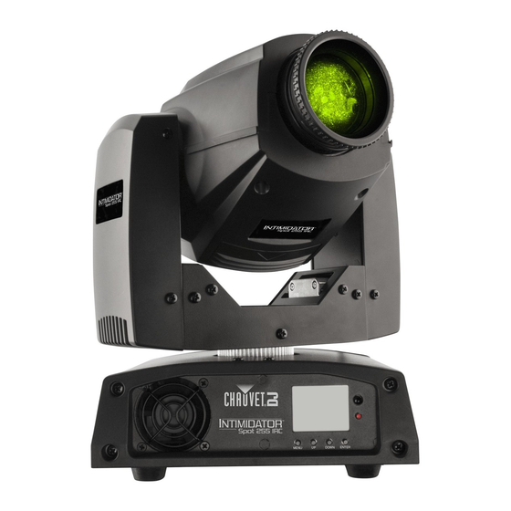
2. I NTRODUCTION Product Overview Manual Focus Lens Yoke Gobo Access Door Cooling Fan LCD Display IR Sensor Indicator LED Menu Front Panel View Buttons Power Out Microphone DMX In/Out Power In Back Panel View Fuse-Holder Intimidator™ Spot 255 IRC User Manual Rev. 2 Page 5 of 24... -
Page 6: Product Dimensions
Product Dimensions 9.1 in 232 mm 13.2 in 337 mm 8.3 in 211 mm Page 6 of 24 Intimidator™ Spot 255 IRC User Manual Rev. 2... -
Page 7: Setup
The power linking diagram shown above corresponds to the North American version of the product ONLY! If using the product in other markets, you must consult with the local Chauvet distributor as power linking connectors and requirements may differ in your country or region. -
Page 8: Mounting
See the Technical Specifications for weight information. The CLP-15 clamp from Chauvet is appropriate for this product. · When mounting the product overhead, always use a safety cable. Mount the product securely to a rigging point, whether an elevated platform or a truss. -
Page 9: Operation
4. O PERATION Control Panel To access the control panel functions, use the four buttons located underneath the display. Operation Button Function Press to find an operation mode or to back out of the current menu <MENU> option <UP> Press to scroll up the list of options or to find a higher value <DOWN>... -
Page 10: Configuration (Dmx)
Configuration Set the product in DMX mode to control with a DMX controller. Connect the product to a suitable power outlet. (DMX) Connect a DMX cable from the DMX output of the DMX controller to the DMX input socket on the product. Starting Address When selecting a starting DMX address, always consider the number of DMX channels the selected DMX mode uses. -
Page 11: Dmx Assignments
5. DMX A SSIGNMENTS DMX13CH Channel Function Value Percent/Setting 000ó255 0–540° Fine Pan 000ó255 Fine control of pan Tilt 000ó255 0–270° Fine Tilt 000ó255 Fine control of tilt Speed 000ó255 Pan/Tilt speed (fast to slow) 000ó006 White 007ó013 Yellow 014ó020 Pink 021ó027 Green... -
Page 12: Dmx13Ch (Cont.)
Channel Function Value Percent/Setting DMX13CH 000ó015 Open (cont.) Prism 016ó255 Prism on Dimmer 000ó255 0–100% 000ó003 Closed 004ó007 Open Shutter 008ó215 Strobe effect with increasing speed 216ó255 Open 000ó007 No function 008ó027 Blackout while pan/tilt moving 028ó047 Blackout while moving gobo wheel Disable blackout while pan/tilt/moving gobo 048ó067 wheel... -
Page 13: Dmx8Ch
Channel Function Value Percent/Setting DMX8CH 000ó255 0–540° Tilt 000ó255 0–270° 000ó006 White 007ó013 Yellow 014ó020 Pink 021ó027 Green 028ó034 035ó041 Light Blue 042ó048 Kelly Green 049ó055 Orange 056ó064 Dark Blue 065ó071 White + Yellow Color Wheel 072ó078 Yellow + Pink 079ó085 Pink + Green 086ó092... -
Page 14: Dmx8Ch (Cont.)
Channel Function Value Percent/Setting DMX8CH 000ó015 Open (cont.) Prism 016ó255 Prism on Dimmer 000ó255 0–100% 000ó003 Closed 004ó007 Open Shutter 008ó215 Strobe effect with increasing speed 216ó255 Open Configuration Set the product in one of the standalone modes to control without a DMX controller. ·... -
Page 15: Manual Test Mode
Manual Test Mode To test or control any function of the Intimidator™ Spot 255 IRC through the LCD display menu, follow the instructions below: Press <MENU>. Use <UP> or <DOWN> to choose Run Mode. Press <ENTER>. Use <UP> or <DOWN> to select Manual Test. Press <ENTER>. -
Page 16: Display
Display You are able to flip the LED display for easy readability in any mounting situation. To select your display angle: Press <MENU>. Use <UP> or <DOWN> to choose Setup. Press <ENTER>. Use <UP> or <DOWN> to select Screen Reverse. Press <ENTER>. -
Page 17: Master/Slave Mode
Master/Slave The Master/Slave mode allows a single Intimidator™ Spot 255 IRC (the master) to control the actions of one or more Intimidator™ Spot 255 IRC units (the slaves) without Mode the need of a DMX controller. The master will be set to operate in either Automatic or Sound-Active mode, while the slaves will be set to operate in Slave mode. -
Page 18: Ir Mode
IR mode allows the product to be controlled with an infrared remote controller. The IR Mode IRC-6 can remotely set the product to various modes; adjust the color, speed and sensitivity; and set the strobe. To set the product to IR mode, do the following: Make sure the product is plugged into a power source and not connected to a DMX cable. -
Page 19: Zero Adjust Mode
Zero Adjust The Intimidator™ Spot 255 IRC contains a passcode-protected mode which allows you to calibrate and adjust several of the product’s operating parameters. Mode In order to access this mode, do the following: Press and hold <MENU> for at least 10 seconds. Use <UP>... -
Page 20: Changing Gobos
Changing To change the gobos in the Intimidator™ Spot 255 IRC, do not remove the gobo wheel. Simply: Gobos Disconnect product from power outlet. Place the product on a flat, level surface with the front facing up. Access the gobo plate by removing the cover on the moving head. By hand, gently push downward on the cover, in the direction of the debossed arrowhead on the cover. -
Page 21: Technical Information
6. T ECHNICAL NFORMATION Product Dust build up reduces light output performance and can cause overheating. This can lead to reduction of the light source’s life. To maintain optimum performance and Maintenance minimize wear, you should clean your lighting products at least twice a month. However, be aware that usage and environmental conditions could be contributing factors to increase the cleaning frequency. -
Page 22: Technical Specifications
7. T ECHNICAL PECIFICATIONS Dimensions and Length Height Width Weight (pointing upward) Weight 8.3 in (211 mm) 9.1 in (232 mm) 13.2 in (337 mm) 12.6 lb (5.7 kg) Note: Dimensions in inches rounded to the nearest decimal digit. Power Power Supply Type Range Voltage Selection... -
Page 23: Returns
Be sure to pack the product properly. Any shipping damage resulting from inadequate packaging will be your responsibility. FedEx packing or double-boxing are recommended. Chauvet reserves the right to use its own discretion to repair or replace returned product(s). Intimidator™ Spot 255 IRC User Manual Rev. 2... -
Page 24: Contact Us
+32 9 388 93 97 Outside the U.S., United Kingdom, Ireland, Mexico, or Benelux, contact the dealer of record and follow their instructions to request support or to return a product. Visit the Chauvet website for contact information. Page 24 of 24...
Need help?
Do you have a question about the Intimidator Spot 255 IRC and is the answer not in the manual?
Questions and answers