
Related Manuals for Nice Apollo 1500


Summary of Contents for Nice Apollo 1500
- Page 1 Nice Apollo Swing Gate Opener Model 1500 Model 1600 Vehicular Swing Gate Opener Revision 1.0.0.0_2-2014...
-
Page 2: Table Of Contents
3.1 - Properly installed safety devices 23 - EXPLODED VIEWS 3.2 - Safety signs, notices to personnel warning signs 23.1 - 1500 Single gate control box 3.3 - Gate system safety devices 23.2 - 1600 Dual gate control box 3.4 - Infrared beams and warning signs 23.3 - Actuator front... -
Page 3: Extremely Important
1 - OVERVIEW The Apollo Model 1500/1600 Swing Gate Operator is designed to handle swing gates up to 16 feet in length and 600 pounds each. This gate operator is not a “do-it-yourself” installation. A qualified installation company should be contacted to install this gate operator to ensure a proper and safe installation. -
Page 4: Gate Information
• Loops and loop detectors, photo-cells or other equivalent devices must be 2 - GATE INFORMATION installed with this gate operator to prevent the gate from closing on vehicular traffic 2.1 - ASTM F2200 • The speed limit for vehicular traffic through the gate area is 5 MPH. Install Gates shall be constructed in accordance with the provisions given for the speed bumps and signs to keep vehicular traffic from speeding through the appropriate gate type listed, refer to ASTM F2200 for additional gate types. -
Page 5: Gate System Safety Devices
3.3 - Gate system safety devices • A minimum of two (2) WARNING SIGNS shall be installed, one on each side of the gate where easily visible. Automatic gate operators are designed to move a heavy steel gate. Great • Test all features for proper functions before placing the automatic vehicular amounts of force are sometimes used to move these heavy systems. - Page 6 4.3.16 Protrusions shall not be permitted on any gate, refer to ASTM F2200 4.3.39 Safety sensors must be present at all times. The hard wired safety for exceptions, if any. sensors must be arranged and installed in such a manner so that 4.3.17 Gates shall not be designed, constructed and installed in such a the communication between gate operator and sensor(s) are never interrupted or severed by mechanical damage or movement.
-
Page 7: Solar Panel Chart
6 - SOLAR PANEL CHART This Apollo Gate Operator is 12 Volt DC (Direct Current) powered. A 12 Volt sealed battery (33 ampere hour minimum for AC charged systems, 70 ampere hour minimum for solar charged systems) with connecting posts located on the top is recommended. The following table should be used as a guide for capacity of operation of operators only, additional options may reduce the daily usage. -
Page 8: Parts Identification
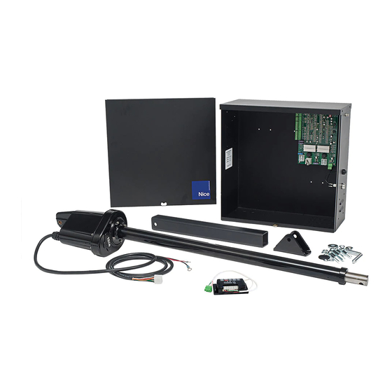
7 - PARTS IDENTIFICATION 416 Actuator with 8’ harness 416X - Slave actuator with 38’ harness (Supplied with 1600) Control Box #11111B Gate Attach Bracket #10025215 Bolt Kit Pivot Arm #1116 (2 with 1600) (2 with 1600) (2 with 1600) -
Page 9: Pull To Open Installation
8 - PULL TO OPEN INSTALLATION IMPORTANT - Never weld parts to the gate or posts when the operator circuit board is powered. Doing so may damage the board beyond repair. 8.1 - PIVOT ARM INSTALLATION - Location of Pivot Point The following instructions provide up to 105°... -
Page 10: Push To Open Installation
9 - PUSH TO OPEN INSTALLATION 9.1 - PIVOT ARM INSTALLATION - Location of Pivot Point Measurements are taken from the center of pivot of the gate hinge. The pivot arm needs to be securely mounted to the hinge post or equivalent mounting surface. It is recommended to weld the pivot arm to a metal post. -
Page 11: Actuator Mounting
10 - ACTUATOR MOUNTING Mount the actuator to the pivot arm as shown. Please notice the washer goes above the actuator flange. The lock nut should be tight to prevent movement or shifting when the actuator is running. This will also prevent excessive “bounce”... -
Page 12: Gate Bracket Mounting
Run the unit through a complete cycle to insure proper operation then mount permanently . 14 - LIMIT SWITCH ADJUSTMENT 14.1 - Model 1500 (single gate operator) Remove limit switch end caps Remove the limit screw end caps. A shown in the figure to the right. -
Page 13: Control Board Connections
15 - 635/636 CONTROL BOARD CONNECTIONS 8 Pin White Connector (two on 636 Master & Slave) TIMER TO CLOSE CURRENT SENSE DELAY TIMER TO CLOSE OPT. SLAVE DISABLE MASTER DISABLE MAX RUN TIMER OPT. MAX RUN TIMER VALUE TIMER TO CLOSE VALUE “STOP”... -
Page 14: Control Board Adjustments
16 - 635/636 CONTROL BOARD ADJUSTMENTS PROGRAM SWITCHES Description Factory Setting TIMER TO CLOSE - Automatically closes gate ON - Close timer enabled OFF - Close timer disabled CURRENT SENSITIVITY OPTION - Delays current sensing from start up ON - 4 second delay OFF - 2 second delay TIMER TO CLOSE OPTION ON - timer to close works only when open limit switch is activated OFF - timer to close works from any open gate position... -
Page 15: Nice Receivers & Transmitters
17 - NICE RECEIVERS AND TRANSMITTERS 17.1 - Wiring Instructions for Nice receivers Connect terminals 1-4 of the receiver to the 635/636 circuit board. Terminal 1 - 12V Terminal 2 - GND Terminal 3 - INP Terminal 4 - GND To Control another gate or device within close proximity connect wires from activation terminals of second operator or device to... -
Page 16: General Layout & Safety Access
18 - GENERAL LAYOUT AND SAFETY ACCESS Entrapment Protection Inputs - Typical Installation Diagram Utilizing Loop Sensors and Photocells Loop (safety) 4’ min. from closed gate 4’ min. from closed gate Loop (shadow) Photo 2 Photo 2 Loop (safety) Loop (exit) Figure - LAYOUT FOR IN-GROUND LOOPS Entrapment Protection Inputs - Typical Installation Diagram Utilizing Photocells Photo... -
Page 17: Maintenance Schedule
20 - MAINTENANCE SCHEDULE Table 2 1 Year 6 Months Battery Check the battery for any leakage or loose connections. Batteries should be replaced when ● ● depleted If equipped - Check emergency vehicle access device for proper operation Fire Dept ● ... - Page 24 24 - WARRANTY Nice Group USA Limited Warranty – 2 (TWO) YEARS Nice Group USA (“Manufacturer”) warrants this product shall be free from defects in materials and workmanship for a period of 2 years from the manufacture date. These warranties are in lieu of all other warranties expressed or implied and shall be considered void if the product is damaged due to, but not limited to, improper installation, improper use, terrorism or acts of God.
-
Page 25: Installation Checklist
25 - INSTALLATION CHECKLIST Left box is for installer check off and the right box is for customer check off. ❑ ❑ 1. The gate has been checked to make sure it is level and moves freely in both directions. ❑ ❑ 2. Potential pinch areas have been guarded so as to be inaccessible OR have contact and/or non-contact obstruction sensing devices installed. - Page 26 Contact us Nice Group USA Inc. 12625 Wetmore Road Suite 218 San Antonio, TX 78247 Ph. +1.210.545.2900 Fax +1.210.545.2915 www.niceapollo.com www.facebook.com/NiceApollo...
Need help?
Do you have a question about the 1500 and is the answer not in the manual?
Questions and answers
Limit switch is malfunctioning
To fix a malfunctioning limit switch on a Nice Apollo 1500:
1. Check the limit switch wiring connections to ensure they are secure and correctly connected.
2. Adjust the limit screw:
- For more extension: turn the limit screw counterclockwise.
- For less extension: turn the limit screw clockwise.
- For more retraction: turn the limit screw clockwise.
- For less retraction: turn the limit screw counterclockwise.
3. Hold the LED enable button while adjusting and watch for the MASTER OPEN limit LED to illuminate.
4. Do not overextend the extension tube beyond 66 inches to avoid unscrewing it from the drive screw.
If the problem persists, inspect the switch for physical damage and replace it if necessary.
This answer is automatically generated