Table of Contents
Advertisement
www.proform.com
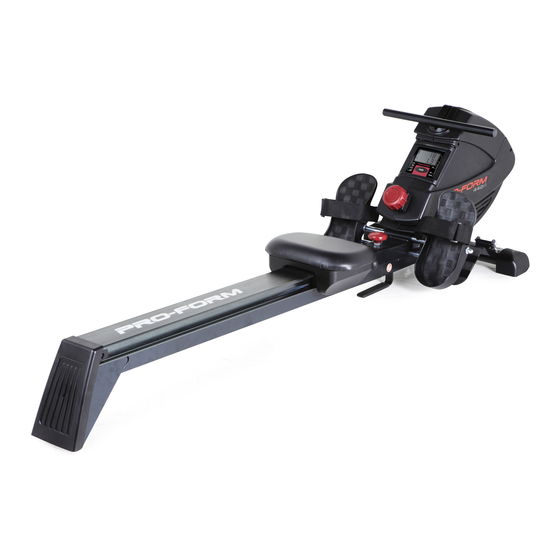
Model No. PFRW3914.0
Serial No.
Write the serial number in the space
above for reference.
Serial Number
Decal
ACTIVATE YOUR
WARRANTY
To activate your warranty today,
go to www.proformservice.com/
registration.
CUSTOMER CARE
For service at any time, go to
www.proformservice.com.
Or call 1-888-533-1333
Mon.–Fri. 6 a.m.–6 p.m. MT
Sat. 8 a.m.–12 p.m. MT
Please do not contact the store.
CAUTION
Read all precautions and instruc-
tions in this manual before using
this equipment. Keep this manual
for future reference.
USER'S MANUAL
Advertisement
Table of Contents

Related Manuals for Pro-Form 440R


Summary of Contents for Pro-Form 440R
- Page 1 www.proform.com Model No. PFRW3914.0 Serial No. USER’S MANUAL Write the serial number in the space above for reference. Serial Number Decal ACTIVATE YOUR WARRANTY To activate your warranty today, go to www.proformservice.com/ registration. CUSTOMER CARE For service at any time, go to www.proformservice.com.
-
Page 2: Table Of Contents
TABLE OF CONTENTS WARNING DECAL PLACEMENT ............. . .2 IMPORTANT PRECAUTIONS . -
Page 3: Important Precautions
IMPORTANT PRECAUTIONS WARNING: To reduce the risk of serious injury, read all important precautions and instructions in this manual and all warnings on your rower before using your rower. ICON assumes no responsibility for personal injury or property damage sustained by or through the use of this product. - Page 4 STANDARD SERVICE PLANS...
-
Page 5: Before You Begin
BEFORE YOU BEGIN Thank you for selecting the new PROFORM 440 R this manual, please see the front cover of this manual. ® rower. Rowing is an effective exercise for increasing To help us assist you, note the product model number cardiovascular fitness, building endurance, and toning and serial number before contacting us. -
Page 6: Part Identification Chart
PART IDENTIFICATION CHART Use the drawings below to identify the small parts needed for assembly. The number in parentheses below each drawing is the key number of the part, from the PART LIST near the end of this manual. The number following the key number is the quantity needed for assembly. -
Page 7: Assembly
ASSEMBLY • To hire an authorized service technician to • Left parts are marked “L” or “Left” and right parts assemble this product, call 1-800-445-2480. are marked “R” or “Right.” • Assembly requires two persons. • Assembly requires only the included tools. •... -
Page 8: Next, Unwrap The Bungee Cord (45) From The
3. Remove the Frame Pin (37) from the Frame (39). Next, unwrap the Bungee Cord (45) from the Frame (39). Then, remove the 1/2" Locknut (54), the two M13 x 22mm Washers (33), and the 1/2" x 100mm Bolt (36) from the Frame (39). Note: The parts that you removed will be used in steps 4 and 5. - Page 9 5. Move the Seat (28) to the front of the Rail (8). Have a second person raise the Rail (8) to the vertical position. Fully insert the Frame Pin (37) into the indicated hole in the Rail Bracket (41) so that it holds the Rail in place.
- Page 10 7. See the inset drawing. Route the end of the Bungee Cord (45) around the Small Pulley (5) on the Rear Stabilizer (3) as shown. Make sure that the Bungee Cord (45) is not twisted. Attach the Bungee Clip (97) to the indi- cated hole in the Rail Attachment Bracket (43).
-
Page 11: Frame (39
9. Orient the Rail Cover (18) as shown. Attach the Rail Cover (18) to the Rail (8) with four M5 x 8mm Screws (12). 10. Remove the Frame Pin (37) from the Rail Bracket (41), and lower the Rail (8) to the floor. Next, insert the Frame Pin (37) into the Frame (39) and into the Rail Bracket (41). -
Page 12: Frame (39
11. Identify the Stop Rod (35), which is slightly shorter than the Pedal Axle (not shown). Insert the Stop Rod (35) into the Frame (39) and center it. Next, slide a Pedal Stop (34), an M8 x 20mm Washer (16), and an M8 Split Washer (15) onto each side of the Stop Rod (35). - Page 13 14. Attach a Foot Plate (52) to one side of the Front Stabilizer (50) with a Foot Plate Pin (51). Attach the other Foot Plate (not shown) to the other side of the Front Stabilizer (50) in the same way. 15.
-
Page 14: How To Use The Rower
HOW TO USE THE ROWER HOW TO ADJUST THE RESISTANCE HOW TO DO CURL EXERCISES WITH THE ROWER To vary the Stand on the foot intensity of your plates, facing exercise, you can the rower. Hold adjust the resis- the row bar with tance that you Resistance an underhand or... -
Page 15: Frame (39
HOW TO FOLD AND STORE THE ROWER HOW TO UNFOLD THE ROWER The rower can be stored in a folded position to con- To unfold the rower, see assembly step 10 on page serve space. Store the rower in a location where 11. - Page 16 FEATURES OF THE CONSOLE HOW TO USE THE CONSOLE The easy-to-use console features several display Make sure that batteries are installed in the console modes that provide instant exercise feedback dur- (see assembly step 15 on 13). If there is a sheet of ing your workouts.
-
Page 17: Fcc Information
FCC INFORMATION This equipment has been tested and found to comply with the limits for a Class B digital device, pursuant to part 15 of the FCC Rules. These limits are designed to provide reasonable protection against harmful interference in a residential installation. This equipment generates, uses, and can radiate radio frequency energy and, if not installed and used in accordance with the instructions, may cause harmful interference to radio communications. -
Page 18: Maintenance And Troubleshooting
MAINTENANCE AND TROUBLESHOOTING MAINTENANCE HOW TO GREASE THE ROLLERS Inspect and tighten all parts of the rower regularly. If the rollers beneath the seat squeak when you use Replace any worn parts immediately. the rower, apply a small amount of the included grease to a paper towel, and spread a thin layer evenly along To clean the rower, use a damp cloth and a small the rail where the rollers move. -
Page 19: Exercise Guidelines
EXERCISE GUIDELINES Aerobic Exercise—If your goal is to strengthen your WARNING: cardiovascular system, you must perform aerobic Before beginning this exercise, which is activity that requires large amounts or any exercise program, consult your physi- of oxygen for prolonged periods of time. For aerobic cian. - Page 20 SUGGESTED STRETCHES The correct form for several basic stretches is shown at the right. Move slowly as you stretch; never bounce. 1. Toe Touch Stretch Stand with your knees bent slightly and slowly bend forward from your hips. Allow your back and shoulders to relax as you reach down toward your toes as far as possible.
- Page 21 NOTES...
-
Page 22: Part List
PART LIST Model No. PFRW3914.0 R0114B Key No. Qty. Description Key No. Qty. Description M2.5 x 10mm Screw Frame Cover Rear Stabilizer Cover 1/2" Locknut Rear Stabilizer Nut Cap Reed Switch Right Stabilizer Cap Small Pulley Left Pedal M10 x 30mm Screw Pedal Axle Rail Bracket Cap M10 x 48mm Screw... -
Page 23: Exploded Drawing
EXPLODED DRAWING Model No. PFRW3914.0 R0114B... -
Page 24: Ordering Replacement Parts
ORDERING REPLACEMENT PARTS To order replacement parts, please see the front cover of this manual. To help us assist you, be prepared to provide the following information when contacting us: • the model number and serial number of the product (see the front cover of this manual) •...
Need help?
Do you have a question about the 440R and is the answer not in the manual?
Questions and answers