
Related Manuals for Imagine Selenio X50

Summary of Contents for Imagine Selenio X50
- Page 1 Installation and Operation Manual Selenio X50 Broadcast‐Quality Up/Cross/Downconverter Version 4.0...
- Page 2 Publication Information © 2014 Imagine Communications Corp. Proprietary and Confidential. Imagine Communications considers this document and its contents to be proprietary and confidential. Except for making a reasonable number of copies for your own internal use, you may not reproduce this publication, or any part thereof, in any form, by any method, for any purpose, or in any language other than English without the written consent of Imagine Communications. All others uses are illegal. This publication is designed to assist in the use of the product as it exists on the date of publication of this manual, and may not reflect the product at the current time or an unknown time in the future. This publication does not in any way warrant description accuracy or guarantee the use for the product to which it refers. Imagine Communications reserves the right, without notice to make such changes in equipment, design, specifications, components, or documentation as progress may warrant to improve the performance of the product. Trademarks Selenio and Selenio X50 are trademarks of Imagine Communications or its subsidiaries. Adobe® and Adobe After Effects® are registered trademarks of Adobe Systems Incorporated in the United States and/or other countries. Microsoft® and Windows® are registered trademarks of Microsoft Corporation. HD‐BNC is a trademark of Amphenol Corporation. Manufactured under license from Dolby Laboratories. Dolby and the double‐D symbol are registered trademarks of Dolby Laboratories. DTS Neural audio products are manufactured under license from DTS Licensing Limited. DTS and the Symbol are registered trademarks & the DTS Logos are trademarks of DTS, Inc. © 2008‐2010 DTS, Inc. All other trademarks and trade names are the property of their respective companies. Contact Information Imagine Communications has office locations around the world. For locations and contact information see: http://www.imaginecommunications.com/contact‐us/ Support Contact Information For support contact information see: Support Contacts: http://www.imaginecommunications.com/services/technical‐support/ eCustomer Portal: http://support.imaginecommunications.com...
-
Page 3: Table Of Contents
Contents Preface ......................... ix Manual Information ...................... ix Purpose ........................ix Audience ........................ix Revision History ......................ix Writing Conventions ....................x Obtaining Documents ....................x Unpacking/Shipping Information .................x Unpacking a Product ....................x Product Servicing ....................... xi Returning a Product ....................xi Restriction on Hazardous Substances (RoHS) Directive .......... - Page 4 Contents Rack Mounting ......................7 Jumpers ........................10 Selecting an External Balun ..................10 Configuring Network Settings ................... 11 Changing the PC Network Settings ................13 Remote Control of the X50 ..................15 Preparing for Remote Control via Control Panel ............16 Selecting a Remote Unit to Control ................
- Page 5 Output Format Selection .................... 49 I-Wings and 3D Modes .................... 49 Audio Processing ......................50 Audio Metadata ......................50 Dolby E Alignment ....................51 Logo Generator ......................53 Basic Steps to Installing Logo Files ................53 Step 1: Install LogoCreator Software ................ 54 Step 2: Convert Files to the .mg2 Format ..............
- Page 6 Contents Audio Input ........................94 AES/DARS ........................ 94 Analog ........................95 Audio Output ....................... 95 AES .......................... 95 Analog ........................96 Conversion Capabilities ....................96 Communications ......................96 GPI In/Out ........................ 96 RS-422 ........................97 LAN ......................... 97 Temperature ......................97 Power Consumption ....................
- Page 7 Broadcast-Quality Up/Cross/Downconverter Installation and Operation Manual Version 4.0 August, 2015...
-
Page 9: Preface
Preface Manual Information Purpose This manual details the features, installation, operation, maintenance, and specifications for the X50 Up/Cross/Downconverter. Audience This manual is written for engineers, technicians, and operators responsible for the installation, setup, and/or operation of X50 Up/Cross/Downconverter. Revision History Table P-1 Document Revision History Edition... -
Page 10: Writing Conventions
Preface Writing To enhance your understanding, the authors of this manual have adhered to the following text conventions: Conventions Table P-2 Writing Conventions Term or Convention Description Bold Indicates dialog boxes, property sheets, fields, buttons, check boxes, list boxes, combo boxes, menus, submenus, windows, lists, and selection names Italics... -
Page 11: Product Servicing
Installation and Operation Manual Product Except for firmware upgrades and jumper selections, the X50 is not designed for field servicing. Return the X50 unit to the Harris Customer Service Center for all hardware Servicing upgrades, modifications, or repairs. Returning a In the unlikely event that your product fails to operate properly, contact Customer Service to obtain a Return Authorization (RA) number, and then send the unit back for servicing. -
Page 12: Waste From Electrical And Electronic Equipment (Weee) Directive
Preface Safety Waste from Electrical and Electronic Equipment (WEEE) Directive The European Union (EU) Directive 2002/96/EC on Waste from Electrical and Electronic Equipment (WEEE) deals with the collection, treatment, recovery, and recycling of electrical and electronic waste products. The objective of the WEEE Directive is to assign the responsibility for the disposal of associated hazardous waste to either the producers or users of these products. -
Page 13: Safety Terms And Symbols In This Manual
xiii Installation and Operation Manual Safety Terms and Symbols in this Manual WARNING Statements identifying conditions or practices that may result in personal injury or loss of life. High voltage is present. CAUTION Statements identifying conditions or practices that can result in damage to the equipment or other property. - Page 14 Preface Safety...
-
Page 15: Chapter 1 Introduction
Introduction Product The X50 is a standalone up/down/cross converter in a 1-RU format. The X50 can provide broadcast quality multi-standard conversion along with support for aspect ratio change and Features AFD processing, closed captioning processing, video processing amplifier and video frame synchronization and delay, with built-in color correction. -
Page 16: Video Processing
Chapter 1 Introduction Eight-channel analog audio outputs, balanced RS-422 serial port for external metadata Four GPIO outputs, TTL Video Dual-output processor supporting simultaneous down- and cross conversion; simultaneous up- and ARC conversion Processing Advanced 10-bit image processor ... -
Page 17: Other
Installation and Operation Manual Other 10/100 Ethernet connectivity Store-and-recall AFD presets through CCS-P and SNMP User-selectable LOV modes: Pass, Freeze, Black, and Test Pattern Built-in SD/HD/3G test generator containing cross hatch pattern, color bar signal, black, white, and horizontal sweep with chroma or luma-only signals Clean handling of hot switch on input ... -
Page 18: Front And Back Views
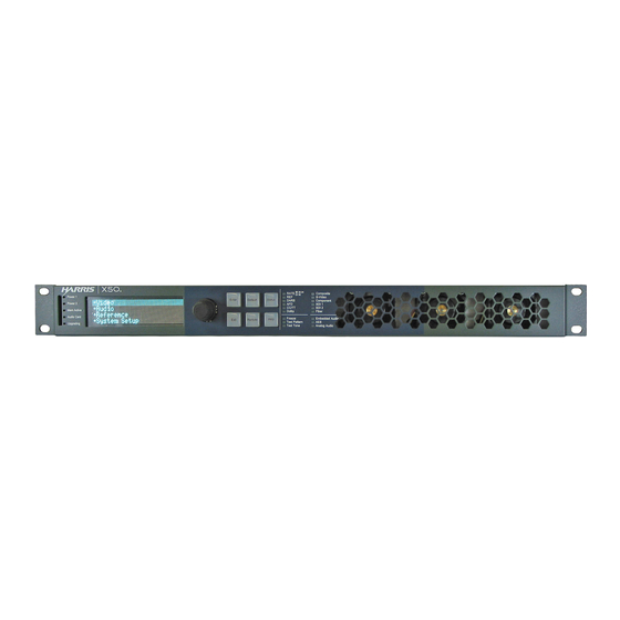
Chapter 1 Introduction Front and Back Views Figure 1-1 Front and Back Views... -
Page 19: Pinouts
Installation and Operation Manual Pinouts Ground Figure 1-2 Female Back Panel Data Pinouts Ground Out4 Out3 Out2 Out1 Figure 1-3 Female Back Panel GPI Pinouts Ch1a Ch1 b Ch2a Ch2b Ch3a Ch3b Ch4a Ch4 b Figure 1-4 Female Back Panel Analog Audio Input and Output Pinouts Signal Figure 1-5 on page 6 illustrates the signal flow for the X50. - Page 20 Chapter 1 Introduction Figure 1-5 X50 Signal Flow...
-
Page 21: Chapter 2 Installation
Installation Preparing for Installation Prior to installing your system, ensure that certain environmental and electrical conditions are met. Electrical Requirements The X50 power supplies have a universal input of 100-240 VAC at 47 to 63 Hz (nominal), 75 W. There is no voltage selector switch. Each frame has space for two power supplies;... - Page 22 Chapter 2 Installation The following items are included: Rear support arms (164-000306Q00) Cable tie bar (164-000305Q00) Brackets (741-983A_Q) Bracket screws (4-40X1/4 PH_Q) Tie bar screws (6-32X3/8 PH) Rack Ears (164-100062Q00) Note: The frame mounting ears and the rack support brackets are reversible. You can install them with the ears at the front and support brackets at the rear, or with the ears at the rear and the support brackets at the front.
- Page 23 Installation and Operation Manual Attach the brackets to the sides of the frame using the screws that are provided. (See Figure 2-3 on page 9.) CAUTION To prevent damage to components inside the frame, do not use screws longer than those provided.
-
Page 24: Jumpers
Chapter 2 Installation Figure 2-5 Installed Support Arms and Cable Relief Bar Jumpers The analog audio input on the X50 can be set to either 600 or Hi-Z impedance. For instructions on changing the jumper settings, see Changing Jumper Settings page 118. -
Page 25: Configuring Network Settings
Installation and Operation Manual Configuring Network Settings When shipped, the X50 is configured with a default IP address, subnet mask, and default gateway. If you intend to control the unit remotely, or connect it to a network hub/switch along with other X50 units, you will need to reconfigure the IP with unique network settings. - Page 26 Chapter 2 Installation Change the IP address by following these steps: Press Enter to navigate to one of the four number sets in the octet. Modify the address value by using the scroll knob to set a new number. Press Enter to move to the next item in the octet, and then repeat step (b) above. Press Exit when you are finished configuring the address.
-
Page 27: Changing The Pc Network Settings
Installation and Operation Manual Changing the PC Network Settings In unusual situations, such as correcting a failed software upgrade, you may need to change your PC network settings. Follow these steps to change the settings: Change the IP Address of the PC to match that of the X50, by following theses steps: Click Start >... - Page 28 Chapter 2 Installation Verify the network settings were accepted by following the ipconfig procedure, as described below: Click Start, point to Programs > Accessories and then click Command Prompt to open the Command Prompt window on the PC. Type the following at the MS-DOS command prompt, and then press ENTER: ipconfig The IP Address, Subnet Mask, and Default Gateway of the PC appear.
-
Page 29: Remote Control Of The X50
Installation and Operation Manual Remote This section provides the following general configuration procedures: Control of Preparing for Remote Control via Control Panel (on page 16) the X50 Selecting a Remote Unit to Control on page 16 X50 broadcast-quality up/cross/downconverter 3rd party hub or switch Microsoft Internet... -
Page 30: Preparing For Remote Control Via Control Panel
Chapter 2 Installation Preparing for Remote Control via Control Panel Control panels remotely control X50 units via broadcast. You will need to configure the switchers and routers in your network accordingly. Follow these steps to prepare your X50 models for remote control: Reconfigure each X50 with unique IP addresses and other appropriate network settings, including shared subnet mask addresses. -
Page 31: Configuring For Web Browser Control
Installation and Operation Manual Note: The light on the Remote button flashes while the unit is remotely controlling a device. To switch to another unit, or to control the local device you are physically operating, press the Remote button, and then select a new device to control. Select <local device >... -
Page 32: Initial Configuration
Chapter 2 Installation Initial Configuration Before you can connect to an X50 using a web browser, you must configure the IP address of the frame. Follow these steps: Connect one end of a crossover or passthrough cable to the Ethernet port on the front of the X50, and then connect the other end of the cable to a PC with the required software. -
Page 33: Exiting The Control Interface
Installation and Operation Manual Exiting the Control Interface To log off the X50 control interface, do one of the following: Close your browser. Navigate to a different page in your browser. Click Logout in the top right corner of the control panel. ... - Page 34 Chapter 2 Installation In the top left portion of the window are SNMP Agent settings. Table 2-1 SNMP Agent Fields of SNMP Tab Field Function Port Number (Can be from 0 to 65535) The network port used by the SNMP agent; port 161 is the default for Read Has to match the “read community”...
- Page 35 Installation and Operation Manual Figure 2-11 Add Trap Destination Window Choose the SNMP version that you would like to use for traps. Choose the IP address of that trap destination. Choose the port number. The default is 162, but an administrator can set this to any number between 0 and 65535.
-
Page 36: Configuring Third-Party Snmp Software Control
Chapter 2 Installation Configuring Third-Party SNMP Software Control SNMP is an industry-standard protocol that allows other manufacturers’ control software to remotely monitor and control the X50. Harris provides MIB files that can be downloaded from the website. Two general MIB files (leitch.mib and ccsAlarm.mib) set up the structure to define parameters and alarms. -
Page 37: Monitoring And Control Using Mibs
Installation and Operation Manual Monitoring and Control Using MIBs Each X50 unit’s MIB can be fully expanded. When you expand an X50 MIB node in the tree view, there are three sub-folders (see Table 2-3). Table 2-3 MIB Sub-Folders Tree View Contents Item Objects... - Page 38 Chapter 2 Installation Navigating Parameters in a Leitch MIB X50 MIBs make it possible to view a parameter’s range, walk a device or a frame, or receive alarm traps for a device (see Figure 2-14). For details on accessing these features, see the documentation that accompanies your third-party control software.
-
Page 39: Chapter 3 Controls
Controls Overview You can control the X50 using many different interfaces: Local front panel X50 controls Remote front panel controls on other X50 units CCS Level 3-enabled control hardware and software products X50 Web browser For detailed information about the operation of Dolby and DTS Neural audio options, see Advanced Audio Processing on page 65. -
Page 40: Push Buttons
Chapter 3 Controls Push Buttons Table 3-1 Push Button Controls Name Function Enter Selects or “takes” an option or value in a parameter Exit Exits from one level in the parameter tree to a higher lever in the tree Default Resets all of the X50 parameters to their default values, and flashes when you have selected a default value for a parameter (to reset all of the parameters using this control, you must press and hold the button for one... -
Page 41: Main Menu Items
Installation and Operation Manual Main Menu Items Table 3-3 Main Menu Name Function Video Provides parameters for changing video settings Audio Provides parameters for changing audio settings Reference Sets the reference standard for the system System Setup Sets the options for general system setup; includes version information, license credits, GPI settings, scripts, power save options, IP address information, output formats, and input audio Input Video Select... -
Page 42: Web Browser Control
Chapter 3 Controls Web Browser Control The Configuration page of the web browser control provides access to parameters (Tree) and to administrative privileges (User Account). Figure 3-2. Configuration Page Figure 3-3. Web Browser Tree View... -
Page 43: System Presets
Installation and Operation Manual System Presets Up to ten parameters in the X50 can be saved to System Presets, for quick recall at a later time. You can save to--and load from--the following locations: Control panel SD-card Web browser user interface ... -
Page 44: Faults (Alarms)
Unit Recovery Using Failsafe Load Procedure In the unlikely event of a loss of control due to software corruption, follow these steps: Download the latest X50 firmware from the Imagine Communications website to a PC connected to the X50. While holding the Enter + Status buttons simultaneously, power cycle the unit. -
Page 45: Aspect Ratio Conversion
Installation and Operation Manual Aspect Ratio Conversion You can set the output aspect ratio conversion using Custom, Standard, or Automatic controls. These three methods are found in the ARC Preset parameter, with the following options. Custom Standard ARCs Anamorphic ... - Page 46 Chapter 3 Controls AFD transmits data in the VANC space of the SDI signal, enabling both 4:3 and 16:9 television monitors to optimally present video with preset ARC and safe area information. Without AFD, converted video may appear distorted or “cut off” when it appears on different monitors.
- Page 47 Installation and Operation Manual Gray regions indicate areas of the picture Bounding box represents that may be cropped by the receiver the coded frame. without significant loss to the viewer. The smallest rectangle enclosing Black regions indicate areas the white regions indicates the area of the picture that do not of essential picture information.
- Page 48 Chapter 3 Controls AFD 4:3 code and description AFD and VI Select Illustration in a parameter options 4:3 coded frame Description WSS name 16:9 Top 16:9 Top Image with a 16:9 aspect ratio as letterbox at the top of a 4:3 coded frame Image with a 14:9 aspect ratio as letterbox at 14:9 Top 14:9 Top...
- Page 49 Installation and Operation Manual AFD 16:9 code and description Illustration in a AFD and VI Select Description 16:9 coded frame parameter options WSS name Image with aspect ratio greater than 16:9 >16:9 in 16:9 None as a vertically centered letterbox in a AFD Code: 0100 16:9 coded frame Image is full frame, with an aspect ratio...
-
Page 50: Output Afd, Vi And Wss
Chapter 3 Controls Examples of Automatic Aspect Ratio Conversion You can enable automatic ARC controls by setting the ARC Preset parameter to AFD, AFD-ALTR, VI, VI-ALTR, WSS, or WSS-ALTR. When you set ARC Preset to AFD and the upstream video has AFD code embedded in it, the system will present the video signal in the appropriate aspect ratio, and generate new downstream AFD code accordingly. - Page 51 Installation and Operation Manual 4:3 to 16:9 conversion AFD and VI Select Illustration in a Conversion Conversion (Alternative) parameter options 4:3 coded frame WSS name 16:9 Top 16:9 Top 14:9 Top 14:9 Top >16:9 >16:9 in 4:3 Full Frame 4:3 Full 16:9 L 16:9 Center 14:9 L...
- Page 52 Chapter 3 Controls 4:3 to 4:3 conversion Conversion AFD and VI Select Illustration in a (Alternative) parameter options 4:3 coded frame Conversion WSS name 16:9 Top 16:9 Top 14:9 Top 14:9 Top >16:9 >16:9 in 4:3 Full Frame 4:3 Full 16:9 L 16:9 Center 14:9 L...
- Page 53 Installation and Operation Manual 16:9 to 4:3 conversion Conversion AFD and VI Select Illustration in a Conversion (Alternative) 16:9 coded frame WSS name parameter options >16:9 in 16:9 None AFD Code: 0100 16:9 Full Anamorphic AFD Code: 1000 4:3 P None AFD Code: 1001 16:9 Prtctd...
-
Page 54: Afd/Vi/Wss Alignment
Chapter 3 Controls 16:9 to 16:9 conversion AFD and VI Select Conversion Illustration in a Conversion parameter options 16:9 coded frame (Alternative) WSS name >16:9 in 16:9 None AFD Code: 0100 16:9 Full Anamorphic AFD Code: 1000 4:3 P None AFD Code: 1001 16:9 Prtctd None... -
Page 55: Closed Captioning And Dvb Teletext Captioning
Installation and Operation Manual The menu option Video > Scalar x > Advanced > AFD Crop Enable must be set to Off. If you set the parameter to On, AFD alignment will not occur. When all three conditions are met and the video input format is interlaced, the output AFD/ VI/WSS code and new aspect ratio will be aligned with the video content. -
Page 56: Vpid (Video Payload Identifier) Enable
Chapter 3 Controls To pass a data type that is more than one packet per frame, set Data Pass to one of the following selections: Pass Packets (Exact) This selection is only available when input and output standard are same; data on certain lines of the input video will be copied to the same line of the output video Pass Packets (Same Line) ... -
Page 57: Color Correction
Installation and Operation Manual Note: Certain video/audio inputs and outputs can be disabled by the power-saving controls under System Setup > Green (Power Save). If a selection or a control related to an interface is missing, check its power save status. Color The color corrector changes the following attributes of an input signal: Correction... -
Page 58: Gamma Correction
Chapter 3 Controls White Slope Normal white knee Increased white knee Decreased white knee Input Figure 3-14 Examples of Increased and Decreased White Slope Black Stretch Normal black knee Increased black knee Decreased black knee Input Figure 3-15 Increased and Decreased Black Knees Gamma Gamma correction is applied to the RGB as a simple power function, and is applied to each component independently. -
Page 59: Custom Splash Screen
Installation and Operation Manual Gamma Correction 3.00 2.00 0.50 0.30 R, G, and B input Figure 3-16 Example of Gamma Corrections to R, G, and B Custom Splash Screen You can add your station’s logo or any other graphic to the startup splash screen on the VFD of the X50. -
Page 60: Frame Rate Conversion
Chapter 3 Controls The SDI Routing Mode makes it possible for you to make the SDI 2 output the same as, or separate from the SDI 1 output. If you select Dual, SDI 1 and SDI 2 can have separate outputs. -
Page 61: Composite Video
Installation and Operation Manual Composite The X50 processes NTSC (SMPTE 170M), PAL-B (ITU 624-2), and PAL-M composite video that complies to ITU-R BT.470-6 standard (with burst amplitude of 300mV), as well as a Video variant that is used commonly in Brazil (with burst amplitude of 287mV). Ensure that you select the correct PAL-M standard for detection. -
Page 62: Auto Route Feature
Chapter 3 Controls Alternately, set the SDI Routing Mode to Linked. This action allows only one output standard on the two SDI outputs: SDI 2 will mirror SDI 1. A larger selection of options is now available in the Analog/HDMI Out Select parameter. Figure 3-19. -
Page 63: Proc Bypass
Installation and Operation Manual Proc Proc Bypass is an option found in the SDI1 Out Format and SDI2 Out Format parameters. In the X50, this function bypasses the scalar and all processing (noise reduction, Bypass detail enhancement, color correction, etc.) but is downstream of the frame synchronization. Output Format Selection The SDI Routing Mode selects whether the SDI 2 output is independent or linked to SDI 1 (This setting also affects the available output formats for SDI2, Analog, and HDMI.) -
Page 64: Audio Processing
Chapter 3 Controls Audio For detailed information about the use of Dolby and DTS Neural options, see Advanced Audio Processing on page 65. Processing The Input Audio Select parameter selects the audio source to be routed to all audio outputs. This pre-empts individual audio controls. The default Map Through option routes demux audio to mux and HDMI outputs, and AES audio to AES and analog outputs. -
Page 65: Dolby E Alignment
Installation and Operation Manual The audio metadata may be inserted into the following outputs: SDI 1 and SDI 2 (Methods A and B) Serial port Once the source is selected, it applies to all of the outputs. Dolby E It is important to maintain a proper timing relationship between the Dolby E header and the first line of video especially when recording video with embedded audio on tape transports. - Page 66 Chapter 3 Controls Figure 3-21. X50 Audio Routing...
-
Page 67: Logo Generator
Installation and Operation Manual Logo Generator The X50 logo generator and inserter provides on-demand insertion of pre-defined static SD-SDI and HD-SDI logo images. Logos used by the X50 must be created or saved in the .mg2 file format, and initially stored on an SD card at your PC workstation. -
Page 68: Step 1: Install Logocreator Software
Chapter 3 Controls Step 1: Install LogoCreator Software All logos used by the X50 must either be generated as .mg2 files, or converted to that format. LogoCreator software is contained in the Icon Soft Tools package, found on our website. For best results, LogoCreator requires a PC with the following system specifications: Intel Pentium III processor at 500 MHz or faster ... - Page 69 Installation and Operation Manual Figure 3-23 LogoCreator Setup Dialog Box Note: If you click the Open button directly in the Logo Set-Up box, the program will only launch files with a .mg2 prefix. If you attempt to open a file with any other prefix, the program will generate error messages.
- Page 70 Chapter 3 Controls To use the original image’s alpha channel, select the Use the alpha key found with image check box. To use a different image for the alpha channel, clear the Use the alpha key found with image check box, and then click the Open button to select a new file for your alpha channel.
- Page 71 Installation and Operation Manual In the upper left corner (Figure 3-27), you can preview the changes you make using the Fill, Opacity, and Logo Position options. (Other functions shown in the window are not supported on the X50.) Figure 3-26 Opening a Logo Figure 3-27 Preview Pane...
- Page 72 Chapter 3 Controls Modifying the Position, Opacity, and Key Level Using the Modify button, you can adjust the logo attributes you defined when you created the logo (you can also make these settings using the X50 controls at Video > Logo). Click the Modify button to open the Logo dialog box, where you defined the logo attributes.
-
Page 73: Step 3: Transfer The Logos To The Sd Card, And To The X50
Installation and Operation Manual Step 3: Transfer the Logos to the SD Card, and to the X50 When your logos have been created or converted to the .mg2 format, save them to your computer hard drive before saving them to the SD card. On the SD card, create a folder named Logos and store the logo files inside that folder. -
Page 74: Rules Engine
Chapter 3 Controls The read-only parameters GPI Input Level Status and GPI Output Level Status display current GPI pin level information. From left to right, the symbols indicate the level status of GPI pins 0 to 7. A value of 1 represents a high, 0 represents a low, and a symbol represents Not Valid—which means the pin is assigned to the opposite direction. -
Page 75: Custom Gpi Output Script
Installation and Operation Manual Where x is the CCSP ID of a device parameter, y is a value for that parameter. At this time, only integer and enum type of parameter assignments are supported. String type parameter assignment is not supported. <comparison op>... -
Page 76: Parameter Control Script
Chapter 3 Controls <comparison op> ::= == | > | < | >= | <= | != <logic op> ::= && | || Comparisons can be ANDed together using &&, and then can be ORed together using ||. The AND operation always has precedence over the OR operation when AND and OR both exist in a condition. - Page 77 Installation and Operation Manual Enabling the Parameter Control Script To enable a parameter control script, set the Activate Script parameter to Enable. Enter your script into the Script (Part I) parameter (maximum 251 characters). If additional script space is needed, use the Script (Part II to IV) parameters. Script Status [RO] reports the parsing and active status of the script.
- Page 78 Chapter 3 Controls Script example: IF PARAM[754]==2 THEN PARAM[755]=2 IF PARAM[754]==3 THEN PARAM[755]=3 IF PARAM[754]==7 THEN PARAM[755]=10 IF PARAM[754]<2 || PARAM[754] > 3 && PARAM[754]<7 THEN PARAM[755]=19 IF PARAM[733]=='AAAA AAAA AAAA AAAA' THEN PARAM[26]=4 Note: Currently, a maximum of 30 statements is allowed in a script. A maximum of 40 assignments is allowed in a statement.
-
Page 79: Chapter 4 Advanced Audio Processing
Advanced Audio Processing Overview To use Advanced Audio Processing options, you will need to purchase the X50OPT-ADVAUD audio submodule, and a number of Software Key License Credits (see Table 4-1 for the available licenses). The number of license credits that you need depends on which audio functions you select for DTS Neural, Dolby Digital (AC-3) Decoder, Dolby Digital (AC-3) Encoder, Dolby E Decoder, or Dolby E Encoder. -
Page 80: Installing The X50Opt-Advaud Audio Submodule
Chapter 4 Advanced Audio Processing Table 4-1 Advanced Audio Processing Modes, Latency, and Credit Cost (Continued) Mode Latency Credit Cost M17: Loudness Control + Dolby Digital Encode 5.1 125.43 ms 1 DDE, 3 DTS M18: Loudness Control + Dolby E Encode 5.1+2.0 3.13 frames 1 DEE, 4 DTS M19: Loudness Control + Dolby E Encode 4x2.0... -
Page 81: Dolby Products
Installation and Operation Manual Dolby Products Figure 4-1 Figure 4-2 show how Dolby is used in typical X50 applications. Dolby Digital (AC-3) and Dolby E decoding takes place at ingest for voice-over. The Dolby LED on the front panel illuminates when an AAP is configured as a Dolby E or Dolby Digital encoder, and the encoder is currently operating. -
Page 82: Dolby-E Alignment
Chapter 4 Advanced Audio Processing Dolby E Encoder L, R C, LFE Up to 8 Inputs Ls, Rs Lb, Rb Internal Dolby E Encoder Metadata Serial In Metadata Gen AAP 1 DE Decoder AAP 2 DE Decoder Dolby E Decoder L, R C, LFE Up to 8... -
Page 83: Aap Internal Metadata
Installation and Operation Manual AAP Internal Metadata Dolby Digital When using Dolby Digital encoding, if you select AAP Internal metadata generator as the Metadata Source one program is available (the Metadata Index parameter is disabled). However, all other metadata sources have up to eight programs available. Use the Metadata Index parameter to select the program you wish to encode. - Page 84 Chapter 4 Advanced Audio Processing Table 4-2 Decoder Behavior Mode Input #1 Input #2 Output Notes [M7] Decoder MUTE PCM #1 DEC #2 PCM #1 DEC #1 MUTE DEC #? Undetermined: one of the streams gets decoded DEC #1 Undetermined: DEC #1 or MUTE MUTE DEC #2 Undetermined: DEC #2 or MUTE...
- Page 85 Installation and Operation Manual Table 4-2 Decoder Behavior (Continued) Mode Input #1 Input #2 Output Notes [M9] DD/DE Decoder PCM #1 DEC #2 DEC #2 DEC #1 DEC #1 DEC #? Undetermined: one of the streams gets decoded DEC #? Undetermined: the DE stream may get decoded DEC #?
- Page 86 Chapter 4 Advanced Audio Processing DTS Neural Products The block diagrams shown in Figure 4-3 Figure 4-5 illustrate the uses of the different DTS Neural Software Key License Credits. UpMix L , R L , R or Upmix Lt , Rt or 2.
- Page 87 Installation and Operation Manual Loudness Control 4 X 2.0 L , R or L , R or Loudness Lt , Rt or Lt , Rt or measurement 2. 0 output 2. 0 input Lo , Ro or Lo , Ro or and control Lw, Rw Lw , Rw...
- Page 88 Chapter 4 Advanced Audio Processing UpMix + Loudness Control L, R L, R or Loudness Upmix Lt, Rt or measurement 2. 0 input 5. 1 output C , LFE processing Lo , Ro or and control Lw, Rw Ls , Rs DownMix + Loudness Control L, R Loudness...
-
Page 89: Dts Neural Surround Audio Upmix
Installation and Operation Manual DTS Neural Surround Audio UpMix Overview The DTS Neural Surround UpMix renders any two channel audio source (stereo, matrix encoded stereo, LtRt, or DTS Neural Surround LwRw) as surround sound. The DTS Neural Surround UpMix can simultaneously position individual elements within the surround field, creating high levels of image stability and granularity. - Page 90 Chapter 4 Advanced Audio Processing Table 4-4 DTS Neural Surround Audio UpMix Parameters Parameter Name Function Options Uninitialized UpMix Status Indicates the state of the AAP mode Running Not Running (bypassed) Not Running Channel Config Controls the output channel configuration ...
-
Page 91: Dts Neural Surround Audio Downmix
Installation and Operation Manual DTS Neural Surround Audio DownMix Overview The DTS Neural Surround DownMix enables 5.1 surround sound to be transported through any stereo infrastructure. The DownMix process is based upon the principle that both natural stereo and 5.1 content are two-dimensional; both contain width and depth spatial attributes. - Page 92 Chapter 4 Advanced Audio Processing Table 4-5 DTS Neural Surround Audio DownMix Parameters (Continued) Parameter Name Function Options 0 Hz LFE Cutoff Specifies the low-pass cutoff frequency of the LFE channel (0 specifies no LFE channel) 60 Hz 80 Hz ...
-
Page 93: Dts Neural Surround Audio Multimerge
Installation and Operation Manual DTS Neural Surround Audio MultiMerge Overview The DTS Neural Surround MultiMerge enables broadcasters to transition from stereo to 5.1 surround sound, providing viewers with a 24/7 surround sound experience. With MultiMerge in line, 5.1 original content is passed unaffected to the viewer while original stereo content is UpMixed to a 5.1 surround sound image. - Page 94 Chapter 4 Advanced Audio Processing Table 4-6 DTS Neural Surround Audio MultiMerge Parameters Parameter Name Function Options Uninitialized MultiMerge Status Indicates the state of the AAP mode Running Not Running (bypassed) Not Running Input Selection Mode Specifies how input channels are selected.
- Page 95 Installation and Operation Manual Table 4-6 DTS Neural Surround Audio MultiMerge Parameters (Continued) Parameter Name Function Options Phantom Center Downmix L/R Encoding Specifies the encoding mode for the left and right Mode channels Hard Center 0 Hz Downmix LFE Cutoff Specifies the cutoff frequency of the input LFE channel...
- Page 96 Chapter 4 Advanced Audio Processing Table 4-7 Input Selection Mode Option Descriptions (Continued) Option Notes Stereo Detect If audio is present on the L/R pair of the 5.1 input, the Aux input is overridden. Information on the C/LFE and Ls/Rs pairs of the 5.1 input is ignored. If audio is present on the Aux input, the 5.1 input is overridden.
-
Page 97: Dts Neural Loudness Control
Installation and Operation Manual DTS Neural Loudness Control Overview The X50 offers two program channels of DTS Neural Loudness Control—a loudness leveling device that uses advanced psycho-acoustic and signal processing techniques to accurately detect and regulate the perceived loudness of stereo and 5.1 sources. Using this feature, you can regulate audio without creating the perception of being “squashed”... - Page 98 Chapter 4 Advanced Audio Processing Presets The Loudness Control feature uses four different presets (Ultra-Light, Light, Medium, and Aggressive). Table 4-8 lists the values that each of these presets represents. Table 4-8 DTS Neural Loudness Control Preset Settings Parameter Name Ultra Light Light Medium...
- Page 99 Installation and Operation Manual Loudness Control Mapping Each Loudness Control menu within each AAP block (DTS Neural Loudness Ctrl 1/2/3/4) corresponds to a loudness control function of a given AAP loudness control mode. Each mode containing LC may have one or more loudness control sections with related control parameter menus.
- Page 100 Chapter 4 Advanced Audio Processing Loudness Control Parameters Table 4-11 DTS Neural Audio Loudness Control Parameters Parameter Name Function Options Enable Loudness Control Function Enables the Loudness Control feature Disable Uninitialized Loudness Control Status Indicates the state of the AAP mode Running ...
-
Page 101: Chapter 5 Specifications
Specifications Video Input 3G/HD/SD-SDI Table 5-1 3G/HD/SD-SDI Input Video Specifications Item Specification Number of inputs 3G: SMPTE 424M (2.97, 2.97/1.001 Gb/s), SMPTE 425 Level A, Level B-DL Standard (YCrCb, 4:2:2, 10-bit with 16 channels of embedded audio) HD: SMPTE 292M (1.485, 1.485/1.001 Gb/s) ... -
Page 102: Fiber
Chapter 5 Specifications Fiber Table 5-2 Fiber Input Specifications Item Minimum Typical Maximum Note OP+SFP+TR13P Single-Mode Transceiver Module Number of LC connector inputs Input wavelength 1260 nm 1620 nm Optical power monitor -2 dB 2 dB accuracy Sensitivity at 270 Mb/s -22 dBm -20 dBm Pathological... -
Page 103: Composite Video
Installation and Operation Manual Table 5-2 Fiber Input Specifications (Continued) Item Minimum Typical Maximum Note Receiver sensitivity at -20 dBm Pathological; 270 Mb/s PRBS 223-1, BER=1E-12 sensitivity:-21 dBm (SMPTE 259M) Receiver sensitivity at -20 dBm Pathological 1.5 Gb/s -21 dBm PRBS 223-1, BER=1E-12 (SMPTE 292M) Receiver sensitivity at 3... -
Page 104: Component Video
Chapter 5 Specifications Component Video Table 5-5 Component Video Input Specifications Item Specification Format Betacam/SMPTE Connector BNC (IEC 169-8) Input level 1.0 V pk-to-pk Impedance 75 Return loss >40 dB, 1 kHz to 6 MHz Genlock Table 5-6 Genlock Input Specifications Item Specification Connector... -
Page 105: Video Output
Installation and Operation Manual Video Output 3G/HD/SD-SDI Table 5-7 3G/HD/SD-SDI Output Video Specifications Item Specification Number of outputs 3G: SMPTE 424M (2.97, 2.97/1.001 Gb/s), SMPTE 425 Standard Level A, Level B-DL (YCrCb, 4:2:2, 10-bit with 16 channels of embedded audio) HD: SMPTE 292M (1.485, 1.485/1.001 Gb/s) ... -
Page 106: Fiber
Chapter 5 Specifications Fiber Table 5-8 Fiber Output Specifications Item Minimum Typical Maximum Note OP+SFP+TR13P Single-Mode Transceiver Module Number of LC connector outputs 3G: SMPTE 424M Standards HD: SMPTE 292M SD: SMPTE 259M Peak wavelength 1280 nm 1310 nm 1340 nm Measured at 25°C... -
Page 107: Hdmi
Installation and Operation Manual HDMI Table 5-9 HDMI Output Specifications Item Specification Number of outputs 1080p/23.98 Standards 720p/59.94 1080i/59.94 720p/50 1080i/50 Connector HDMI Compliance HDMI 1.3 S-Video Table 5-10 S-Video Output Specifications Item Specification NTSC ... -
Page 108: Component Video
Chapter 5 Specifications Component Video Table 5-12 Component Video Output Specifications Item Specification Format Betacam/SMPTE Connector BNC (IEC 169-8) Resolution 12 bits Impedance 75 Return loss >40 dB, 1 kHz to 6 MHz -0.5 dB to 5.5 MHz (Y) Frequency Response -3.27 to 3.0 MHz (Pb/Pr) ... -
Page 109: Analog
Installation and Operation Manual Analog Table 5-14 Analog Audio Input Specifications Item Specification Number of inputs 8 mono channels Type Balanced Connector DB-25, Tascam-style cable snake for balanced 8-channel audio Input audio level 28 dBu to 12 dBu for 0 dBFs (adjustable in 0.5 dB increments) Input Impedance High-Impedance or 600, jumper selectable CMRR... -
Page 110: Analog
>90 dB, 20 Hz to 20 kHz, typical Linearity <1.0 dB (-80 dBu to + 20 dBu), typical Conversion Capabilities Please see the separate X50 Conversion Table for this information, located on the Imagine Communications website. Communications GPI In/Out Table 5-17 GPI In/Out Specifications... -
Page 111: Lan
Installation and Operation Manual RS-422 Table 5-18 RS-422 Specifications Item Specification Standard RS-422 Connector DB-9 Table 5-19 LAN Specifications Item Specification Connector RJ-45 Type 10/100 Ethernet Temperature The X50 requires an ambient temperature of 41º to 95º F (5º to 35º C) with a relative humidity of 10-90% (non condensing). - Page 112 Chapter 5 Specifications...
-
Page 113: Appendix A Laser Safety Guidelines
Laser Safety Guidelines Laser Safety WARNING Use of controls, adjustments, and procedures other than those specified in this document may result in hazardous laser radiation exposure. Optical fiber telecommunication systems use semiconductor laser transmitters that emit infrared light that is normally not visible to the human eye. Although a conventional laser produces a small beam of light, the power density is very high, and it can cause damage to your eyes. -
Page 114: Precautions For Unenclosed Systems
Appendix A Laser Safety Guidelines Do not stare into optical connectors or broken fibers. Ensure technicians have satisfactorily completed an approved training course before performing installation or maintenance. Ensure there are appropriate warning labels near the optical ports of the modules. Precautions for Unenclosed Systems During service, maintenance, or restoration, an optical fiber telecommunication system is considered unenclosed. -
Page 115: Appendix B Audio Bit Manipulation
Audio Bit Manipulation Overview This appendix contains information on the manipulation of bits that occur when using X50 modules. RX Key: N = not recognized, Y = recognized, S = recognized and stored or passed through or both TX Key: N = not transmitted, Y = transmitted... -
Page 116: Channel Status Bits
Appendix B Audio Bit Manipulation Channel Status Bits Table B-1 C-Bit Manipulation Byte Function Remarks [0] Consumer use Set to [1] [1] Professional use [0] Normal audio mode (linear PCM) Passed unmodified [1] Non-audio (non-PCM) 2 to 4 [000] Not indicated Passed unmodified [100] No emphasis [110] 50/15 µs... -
Page 117: Validity And User Bits
Installation and Operation Manual Table B-1 C-Bit Manipulation (Continued) Byte Function Remarks 3 to 6 [0000] Not indicated Set to [0000] [1000] 24 kHz [0100] 96 kHz [1100] 192 kHz [1100] 22.05 kHz [0101] 88.2 kHz [1101] 176.4 kHz [1111] User defined [0] Sample frequency not scaled Set to [0] [1] Sample frequency scaled by 1/... -
Page 118: Miscellaneous Data
Appendix B Audio Bit Manipulation Miscellaneous Data Table B-3 Miscellaneous Data Item RX Specification TX Specification Audio sampling frequency 32 to 48 kHz 48 kHz Audio sampling word 16 to 24 bits 24 bits length... -
Page 119: Appendix C Servicing
Servicing Overview User-serviceable replacement parts are available for the following X50 components: X50OPT-ADVAUD audio submodule for Dolby and DTS Neural options X50SPR-DISP front panel PCB assembly (includes OLED display, shaft encoder, and circuit board) X50SPR-FAN fan module X50SPR-PSU power supply ... -
Page 120: Cover Removal And Replacement
Appendix C Servicing Cover Removal and Replacement Version 1 The Version 1 unit includes a combined front cover/frame lid. Follow these steps to remove and replace the Version 1 front cover and lid: Disconnect both AC power cords. WARNING: You can receive an electric shock from exposed parts of the power supplies. -
Page 121: Version 2 And 3
Installation and Operation Manual Version 2 and 3 Versions 2 and 3 feature a separate front cover and lid. Follow these steps: Disconnect both AC power cords. WARNING: You can receive an electric shock from exposed parts of the power supplies. -
Page 122: Installation Of Advanced Audio Processing Submodule
Appendix C Servicing Installation of Advanced Audio Processing Submodule To use advanced audio processing in the X50, you must install an X50OPT-ADVAUD audio submodule and purchase the appropriate software license keys. The audio submodule kit includes the submodule board, two short screws, one longer screw, and one standoff. The procedure for both versions of the X50 is the same. - Page 123 Installation and Operation Manual Insert a short screw into one of the standoffs, but do not tighten. Remove the loose standoff supplied in the package and slide it under the audio submodule, above the hole where you removed the main board screw. Note: This standoff is not threaded.
-
Page 124: Lcd Or Oled Display Replacement
Appendix C Servicing LCD or OLED Display Replacement The LCD displays found on Version 1 and 2 units are not serviceable. All version 3 models are serviceable, using a blue OLED. For identification: measured diagonally, the Version 1 and Version 2 LCD screens are larger, at 3.5 inches (9.1 cm); Version 3 OLED screens are 3 inches diagonally (7.5 cm). - Page 125 Installation and Operation Manual Remove the six circuit board mounting screws (Figure C-9). Figure C-9 Removal of the Mounting Screws Gently pull the circuit board away from the face of the X50, and discard. Align the new circuit board assembly, and gently press it into place, taking care not to bend the pins on the left side.
-
Page 126: Fan Module Replacement
Appendix C Servicing Fan Module Replacement The front fan modules are individually mounted and connected. An additional fan is located next to the right power supply. Follow these steps to remove and replace a fan: Remove the X50 cover, as described on page 106, ensuring both power supplies are disconnected Snip and remove the plastic ties wraps holding the fan wires. -
Page 127: Power Supply Replacement
Installation and Operation Manual Power Supply Replacement Follow these steps to remove and replace a power supply: Remove the X50 cover, as described on page 106 or page 107,ensuring both power supplies are disconnected. Remove the input and output conductors of the failed power supply by pulling the connector and pressing the clip down. -
Page 128: Shaft Encoder Replacement
Appendix C Servicing Shaft Encoder Replacement There are two possible replacement parts for a broken shaft encoder: a simple shaft encoder (X50SPR-SE) that must be soldered to the front circuit board, or a complete circuit board unit (X50SPR-DISP). To replace a complete circuit board unit because of a broken shaft encoder, see LCD or OLED Display Replacement on page 110. - Page 129 Installation and Operation Manual From the back side of the circuit board, de-solder the two mounting hole pegs and the five through-hole pegs, using a solder sucker and wick (Figure C-15). Through-hole pegs (2) Mounting pegs (2) Through-hole pegs (3) Figure C-15 De-soldering Encoder Pegs From the front of the board, remove any remaining solder.
- Page 130 Appendix C Servicing Insert the new replacement shaft encoder from the front. Figure C-17 Inserting New Shaft Encoder Solder the connections to the back of the circuit board, ensuring the shaft encoder is flush with the circuit board. Figure C-18 New Shaft Encoder Installed...
-
Page 131: Preventing A Broken Shaft Encoder
Installation and Operation Manual Gently press the circuit board back into place, taking care not to bend the pins on the left side. Install the six mounting screws supplied, and then re-attach the fan electrical connectors. Replace the cover as described earlier, and then re-attach the two power cords. Preventing a Broken Shaft Encoder Version 2 units contain a nylon shoulder washer that effectively reduces the chance of physical damage to the shaft encoder. -
Page 132: Changing Jumper Settings
Appendix C Servicing Changing Jumper Settings The analog audio input on the X50 can be set to either 600 or Hi-Z impedance (see Figure C-20 on page 118). There are eight jumpers for this purpose, located near the rear of the main board inside the X50. -
Page 133: Index
Index – Control software, third-party 19 – Correcting color 43 – Active Format Description (AFD) 31 – Custom GPI scripts 60 – Active script 62 – Custom parameter control script 62 Administrator user 18 – Advanced Audio Processing 65 AES connector removal 3 –... - Page 134 Index Password, default 18 – PC network settings 13 Gateway parameter 12 Phasing of SDI 1 and 2 45 General Purpose Interface (GPI) 59 Pinouts 5 Green-Power Save 42 Power requirements 7 Guard band 68 Power save control 42 Presets ARC 31 Help button 26 by country 84...
- Page 135 Installation and Operation Manual – S-video 89 User-scripted management 62 temperature 97 – video input 87 – video output 91 V-bit and U-bit manipulation 103 weight and dimensions 97 Video Subnet Mask 11 analog/composite 47 – Support bracket and relief bar installation 7 –...
Need help?
Do you have a question about the Selenio X50 and is the answer not in the manual?
Questions and answers