Table of Contents
Advertisement
Advertisement
Table of Contents

Related Manuals for Stratasys Dimension Elite


Summary of Contents for Stratasys Dimension Elite
- Page 1 Dimension Elite ® 3D Printer User Guide 204400-0005...
-
Page 2: Legal Notice
Legal Notice © 201 1 Stratasys, Inc. All rights reserved. The Stratasys, Dimension and CatalystEX are information in this document is subject to registered trademarks of Stratasys, Inc. change without notice. STRATASYS, INC. ABSplus is a trademark of Stratasys, Inc. -
Page 3: Table Of Contents
Table of Contents 1 Introduction..........................1 How To Use This Manual ..................2 Learn More!......................2 Recycling .......................2 Safety precautions ....................2 2 Overview ..........................4 3 Setup ............................9 Unpacking......................9 Installing Forklift Access Covers................11 Networking the printer ...................12 Power Connections....................13 Powering on the printer..................14 Installing software ....................16 Establishing network communication with the printer ..........16 Installing System Software on printer................19 Insert Modeling Base .....................20... - Page 4 Physical specifications....................55 Facility specifications .....................55 Workstation specifications..................56 Power specifications ....................56 Environmental specifications ...................56 10 Supplemental Information......................57 Stratasys Limited Warranty Statement ..............57 Declaration of Conformity ..................57 Regulatory and environmental information ..............58 11 Appendix..........................A1 Uninterruptible Power Supply (UPS) Use and Installation..........A1...
-
Page 5: Introduction
Introduction Dimension Elite is designed with ultimate simplicity in mind. The system enables you to build parts quickly, even if you have never used a 3D printer before. The system models with ABSplus™ plastic, so modeled parts are strong and durable. ABSplus also ensures that you will be able to drill, tap, sand, and paint your creations. -
Page 6: How To Use This Manual
Important safety notices and regulatory information • Detailed user instructions You can also find more information at: http://www.dimensionprinting.com or email info@stratasys.com Recycling Visit http://www.stratasys.com/recycle for recycling information. Safety precautions The following precautions ensure the proper use of the printer and prevent the printer from being damaged. - Page 7 The following classifications are used throughout this guide. CAUTION: Indicates a potentially hazardous situation which, if not avoided, may result in minor or moderate injury. WARNING: Indicates a potentially hazardous situation which, if not avoided, could result in serious injury. Hot Surface: The hot surface sign indicates the presence of devices with high tem- peratures.
-
Page 8: Overview
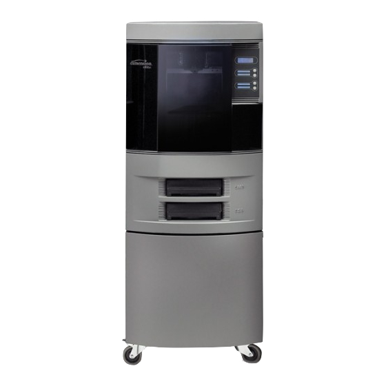
Vista or Windows 7 platform. Dimension Elite’s build envelope measures 203 x 203 x 305 mm (8 x 8 x 12 in). Each material cartridge contains 922 cc (56.3 cu. in.) of usable material — enough to build continuously for... - Page 9 Figure 1 Front view Extrusion head Support material cartridge Extrusion tips Tip wipe assembly Guide rods Display panel Lead screw Purge container Z stage platen Modeling base Model material cartidge Modeling base retainers (2)
- Page 10 Figure 2 Rear view Fan cover UPS connection Circuit breaker Diagnostic connection AC power input RJ-45 Network cable connection...
- Page 11 Figure 3 Material cartridge Figure 4 Modeling base Modeling base CAUTION: DO NOT reuse modeling bases. If a modeling base is reused, calibration errors, poor part quality, and loss of extrusion may occur. Additional modeling bases are available from your reseller.
- Page 12 Network Cable (Blue) 16 Needle Nose Pliers Tip Shroud 17 Cutters Flicker (x5) 18 Allen Wrench Set Flicker Brush 19 Dimension System Software CD Halogen Lamps (x2) 20 CatalystEX CD 10 10x Magnifier Loupe 21 Dimension Elite User Guide CD Anti-Sieze Lubricant...
-
Page 13: Setup
Setup Unpacking This section describes the recommended procedures for unpacking and preparing the printer for its first use. Unpack the printer: WARNING: The printer weighs approximately 128 kg (282 lbs). Use proper moving and lifting techniques when positioning the unit. For your convenience, there are forklift pads built into the bottom of the unit. - Page 14 Figure 6 Foam tubes isolating the extrusion head from the XY-axis frame Foam Tubes (2) Foam Tubes (2) Extrusion Head After unpacking, inspect the printer and report any shipping damage to the carrier.
-
Page 15: Installing Forklift Access Covers
Installing Forklift Access Covers The forklift access covers can be placed over the forklift channels after the printer is placed in its final location. The covers are press-fit in the front and held in place with one screw in the rear. Align the left and right side fork lift covers with the forklift channel and slide the tabs into the slots. -
Page 16: Networking The Printer
Networking the printer There are two methods of connecting your printer to your workstation, over a network or with a direct connection to your workstation. Connecting through a network: Locate the network cable (blue) from the startup kit. Connect the network cable between the printer and the network hub. See Figure 9. -
Page 17: Power Connections
Figure 10 Connecting directly to a workstation Power Connections This section discusses the procedure for preparing all power connections for the printer. CAUTION: Before connecting power to the printer, make sure that the circuit breaker is in the off (down) position. It is located at the rear of the printer, next to the power cord attachment point. -
Page 18: Powering On The Printer
Figure 1 1 Connecting power Powering on the printer WARNING: The build chamber and extrusion-head tip get very hot! The chamber and head tip reach temperatures of approximately 75° C (167° F) and 280° C (536° F) respectively. Personal injury can occur if proper techniques and safety materials are not used. - Page 19 Turn the power switch to the on (I) position. See Figure 13. After the switch is pushed, the system boots up in three to seven minutes. Note: If the printer was off and is at room temperature, it requires approximately 40 minutes to warm up before you can perform any functions.
-
Page 20: Installing Software
Installing software There are two software programs that work with the printer: CatalystEX, installed on your workstation, processes the STL files for printing and communicates with the printer from your workstation. System software, the operating software installed on the printer, controls printer functions. Installing CatalystEX: Locate the CatalystEX CD from startup kit and insert into workstation (PC). - Page 21 A new window, Add 3D Printer, should list your printer in the main window (identified by its UDN). Click on the printer in this window and enter a name and location in the lower portion of the window. Click Add Printer and you are ready to print. Close the Add 3D Printer window. Note: If your printer is not displayed in the “Add 3D Printer”...
- Page 22 Click on the Use the following IP address option. Enter the IP address, Subnet Mask and Default Gateway. Contact your IT Administrator or Internet Service Provider for details regarding IP address information. The IP address should be different from the workstation, the default gateway and subnet mask should match the workstation.
-
Page 23: Installing System Software On Printer
Use the three functions listed above to set your IP address. After setting the final digit of the Internet Protocol (IP) address, move the cursor one more place to the right. The cursor moves to the Netmask (NM) address. Follow the same steps for setting the Netmask (NM) and Gateway (GW) addresses. -
Page 24: Insert Modeling Base
Navigate CatalystEX to the directory where the system software file is located and select the Elite.upg file. System software will now begin to download to the printer. Note: Default system software location for 32 bit systems: C:\Program Files\Dimension\Elite <version> Default system software location for 64 bit systems: C:\Program Files (x86)\Dimension\Elite <version>... -
Page 25: Verifying Tip Depth
Verifying Tip Depth The system’s tip depth has been set at the factory and normally does not need adjustment. During shipment, however, tip depth may shift. Customers that setup and install their own systems need to verify the tip depth setting prior to building. Building with the wrong tip depth can result in models not adhering to the modeling base or a loss of extrusion. - Page 26 Evaluate the etched numbers in each of the six groups. The etched numbers must meet the following criteria: • -5 must be visible in at least one of the six groups. • +10 must not be visible in any of the six groups. Note: The etched numbers can be difficult to see.
-
Page 27: Operation
Operation Display Panel and Keypad The main User Interface to the printer is the Display Panel and Keypad, see Figure 16. Figure 16: Display panel and keypad Display Panel Context-sensitive displays Keypad buttons The display panel and keypad are very easy to use, consisting of a larger multiple-line LCD display on top, and four single-line context-sensitive displays, each with one button (or key). -
Page 28: System Software Overview
System software overview • Idle: If there is no part being built and no part in the build queue, the display will show that the printer is Idle. • Wait for Part or Start Part: If the printer is in Idle and the build queue is empty, you can set it to wait for a part. -
Page 29: Catalystex Overview
CatalystEX overview • General tab: This section is where you can select the model fill style, support style, change the STL units and STL scale. • Orientation tab: This section allows you to rotate, resize and auto-orient your parts. You can also change the view and insert a pause. -
Page 30: Processing Your Stl File For Printing
Processing your STL file for printing Opening your STL file with CatalystEX: Create an STL file using your CAD software. Refer to your CAD software help section for more information about converting your CAD drawings into STL files. Open the CatalystEX. From the File menu select Open STL... - Page 31 Selecting the scale of your STL file: Before you process a part for printing, you can change the size of the part within the build envelope. Every part has a pre-defined size within the STL file. After you have opened the file you can change the size of the part produced from the STL file by changing the scale.
-
Page 32: Inserting A Modeling Base
Adding your STL file to the pack: The Add to Pack button is found on the General, Orientation and Pack tabs. When you click on the Add to Pack button, CatalystEX will add the file that is currently in the preview window (General tab or Orientation tab) to the pack preview window (Pack tab). -
Page 33: Loading Material
Starting a build from the display panel: If Wait for Part has not been activated, you can send the part to the printer and start the part from the display panel after the part has been sent to the printer. From your CatalystEX workstation, send a part to the printer. - Page 34 Find the end of the material filament taped with a “flag”. CAUTION: Be careful when touching the pinch roller on the side of the cartridge. If you Figure 20. roll it backwards, you could draw the material into the cartridge, see for the correct direction to move the cartridge roller.
-
Page 35: Unloading Material
If the printer is in Idle, press the Load Material... button, which will be blinking. Display will prompt with Material Load - Replace Both Cartridges (flashing) Insert material cartridges into their appropriate slot from the front of the printer (Model material cartridge goes in the Top slot;... -
Page 36: Building A Test Part
The panel then prompts with, Replace support? • Press Yes. to unload the Support Material. The panel displays Replacing support, • Press No if you do not wish to unload the support material. After you have made the above choices, the panel displays Unloading for approximately 60 to 75 seconds (the selected materials will be unloaded from the extrusion head). -
Page 37: The Display Panel During Build
The display panel during build The top two lines of the display panel show printer-status messages, see Figure 23. The bottom line of the panel shows the material amounts remaining in the cartridges. Figure 23: Display panel during build Printer Status Model File Name Support Material Model Material... -
Page 38: Canceling A Job
Canceling a Job You can cancel a job at any time while the part is building. Cancel a job: Press Pause. Once the printer stops building, press Cancel Build. The panel displays Are you Sure? Press Yes. The panel displays Build Stopped followed by the part name. The panel prompts you to remove the part and replace the modeling base. -
Page 39: Removing A Completed Part
When removing soluble supports by hand, wear LEATHER gloves. Dimension Elite uses soluble supports - a water-based solution designed to allow you to simply wash away the support material. Your part is left smooth and clean with the fine details intact. The soluble support material can be removed by hand with relative ease, but is designed to be dissolved off of your parts for hands-free part finishing. -
Page 40: Maintenance
Maintenance Follow the simple procedures within this chapter to ensure continued proper operation of the Dimension printer. Startup Kit Tools The Startup Kit contains replacement parts and a set of tools used to help you maintain the system.The following is a list of the tools contained in the Startup Kit. •... - Page 41 Clean door The door glass can be cleaned with any commercial glass cleaner. Empty the purge container The plastic purge container is attached to the right side of the modeling envelope rear wall, see Figure 24. Note: A full purge container may impact part quality. Remove the purge container by grasping it and pushing it upward to release it from its three mounts.
-
Page 42: Clean Fan Filter
500 Hour Maintenance Clean Fan Filter To clean the fan filter: Locate the lower fan on the rear panel of the printer and remove the plastic frame (snaps on and off) that secures the fan filter. See Figure 25. Figure 25: Lower fan location Clean the filter with soap and water, and blot it dry. -
Page 43: Tip Wipe Assembly (Brush/Flicker Assembly)
Tip Wipe Assembly (Brush/Flicker Assembly) Note: The flicker should be replaced after 500 hours. It is only necessary to replace the brush after 2000 hours. Completely power down the printer. See “Powering Off” on page 34. Locate the tip wipe assembly. See Figure 26. - Page 44 Install the new tip cleaning brush, but do not tighten the mounting screws. With a glove on your hand, move the head so that the tips are above the tip cleaning brush. Adjust the tip cleaning assembly until the brush lightly touches the bottom of the Model Tip Shroud.
-
Page 45: Chamber Lamp Replacement
As Needed Maintenance The following maintenance items have no routine schedule but should be tended to as needed. Chamber Lamp Replacement Replace the chamber lamp when it burns out. Note: There are two chamber lamps in the modeling chamber. They are located on the front wall of the chamber. - Page 46 Figure 28: Headplate mounting screw locations Mounting screws Pull the head plate slightly away from the head until the right side of the plate is clear of the mounting screw head. Pivot the right side of the head plate upwards, and rest the right side of the plate on the right mounting screw, as shown in Figure 29.
- Page 47 Locate the shroud, the shroud-mounting screws, and shield, as shown in Figure 30. Figure 30: Shroud and shield location Shroud Shield Shroud Mounting Screws (2) Remove the two shroud mounting screws using a 3 ⁄ ” Allen wrench. WARNING: Screws are very hot!! Use gloves when working in this area of printer! Once the screws are removed, pull the metal shield down to remove.
- Page 48 Check that both the shroud and shield are positioned correctly. Note: Apply a thin coat of anti-seize compound to the threads of the shroud mounting screws. Drive the two shroud-mounting screws into the shroud and tighten, but do not over-tighten the screws! Lower the head cover into position, and tighten both head cover screws.
-
Page 49: Troubleshooting
Troubleshooting Troubleshooting Checklist Problem or error message Solution Verify power cord is securely plugged in. No power Verify that the circuit breaker (at rear of system) and the power switch (on right panel of system) are both in the ON position. Verify AC power is present at wall outlet. -
Page 50: Fault Determination Codes
Problem or error message Solution Display Panel displays The system stopped reporting its status at the Universal Coordinated Time (UCT) shown. Wait for the system to complete building the part. Communication lost at HR:MN UCT The system will automatically restart and display Build Complete. It is then safe to remove the model. -
Page 51: Cycling Power
Cycling power Turn the power switch to the OFF (O) position. The display will show Shutting Down. After the printer has cooled down enough to shut down, the display will go blank. When the display is blank and the printer has shut down, turn the circuit breaker to the OFF (O) position. - Page 52 Recovering From Loss of Extrusion Note: It is recommended that you read and understand this entire procedure before performing any of the work. From the display panel, press Maintenance... Press Machine... Press Head... Gloves: The head area is very hot!! Use leather gloves when working in this area of printer! With the Phillips-head screwdriver provided in the Startup Kit, release the two screws securing the head assembly (see...
- Page 53 If the purge was successful: Continue to run both filament motors forward and slowly swivel the head closed. Be careful to not pinch the filament or the head wiring when closing the head. Once the head is closed, tighten both of the swivel head screws, ¼ turn. iii.
- Page 54 Remove both drive block assemblies from the swivel part of the head. Set a material cartridge on top of the tray to support the removed drive block assemblies. Remove the support drive block first. Use a 7 ⁄ ” Allen wrench to remove the two screws securing the motor assembly as shown in Figure 33.
- Page 55 With the drive blocks removed, inspect liquefier tube inlet area. Inspect the model liquefier inlet tube, and the support inlet funnel covering the support liquefier inlet tube (see Figure 34.) If material is extended out from the inlet tube: Gently remove material with the bronze brush or needle-nose pliers, if necessary.
- Page 56 1 1. Clean the inside of the liquefier inlet tubes. Carefully insert a 1 ⁄ ” Allen wrench into the liquefier inlet tubes and gently push forward until it stops (about 1 ⁄ ” Replace both drive-block assemblies. Install the model drive block assembly first. Make sure the block is seated flush against the swivel plate.
-
Page 57: Support
Support Customer Support Contact your local reseller for technical support. When contacting your reseller please provide the following: • Your name. • Your telephone number. • System model. • System serial number. • System software build number. • CatalystEX version number. •... -
Page 58: Recycling
Recycling Visit http://www.stratasys.com/recycle for recycling information on material cartridges. Figure 35 Recycling Codes System Component Materials Recycling Code Modeling bases All packaging materials can be recycled per your local recycling guidelines. -
Page 59: Printer Specifications
Printer Specifications Physical specifications Height 1041 mm (41 in) Width 686 mm (27 in) Depth 914 mm (36 in) Weight 128 kg (282 lbs) Facility specifications Installation location Stable flat surface capable of holding 136 kg (300 lbs). Power Requirements 100–240VAC ~ 12 - 7A 50/60Hz 1200W dedicated circuit within 2 m (80 in.) Do not use an extension cord or a power strip, using these can possibly cause intermittent power issues.) -
Page 60: Workstation Specifications
Workstation specifications Operating System Microsoft Windows XP, Microsoft Windows Vista or Microsoft Windows 7 Processor Minimum: 2.4 GHz Faster processors will shorten job processing times Minimum: 1GB (2GB for Windows Vista or Windows 7) Recommended: 2GB (3GB for Windows Vista or Windows 7) Hard Disk Installation: 90MB Monitor graphics reso-... -
Page 61: 10 Supplemental Information
10 Supplemental Information Stratasys Limited Warranty Statement A copy of the warranty is available upon request from info@stratasys.com. Declaration of Conformity Declaration of Conformity Stratasys Inc. Manufacturer 7665 Commerce Way Eden Prairie, MN 55344-2080 EU Representative Tim B. Heller Type of Equipment:... -
Page 62: Regulatory And Environmental Information
Regulatory and environmental information EMC Class A Warning WARNING: This is a Class A product. In a domestic environment this product may cause radio interference in which case the user may be required to take adequate measures. FCC Statements (U.S.A.) The U.S. - Page 63 Disposal of waste equipment by users in private households in the European Union This symbol on the product or on its packaging indicates that this product must not be disposed of with your other household waste. Instead, it is your responsibility to dispose of your waste equipment by handing it over to a designated collection point for the recycling of waste electrical and electronic equipment.
-
Page 64: Appendix
1 1 Appendix Uninterruptible Power Supply (UPS) Use and Installation The intent of the Uninterruptible Power Supply (UPS) shutdown feature on Dimension and uPrint 3D printers is to prevent required maintenance and/or system damage by safely shutting the system down in the event of an uncontrolled loss of power. Whether an in-process build of a part will complete successfully is dependent on the battery life of the selected UPS and the duration of the power outage. - Page 65 Figure 36: Wired-And configuration Parts List – Cable, UPS to 3D Printer Item Nomenclature / Description Material Specification Conn, Hsg, Plug, 9Pos AMP - 205204-9 Pin, Male, 24-20 AWG AMP - 1-66506-0 Shell, Size 1, 9-Pin w/Grommets AMP - 748677- 1 Jackscrew Pair 4-40, Knurled AMP - 747784-3 XX.x...
- Page 66 Figure 37: UPS Cable Diagram...
Need help?
Do you have a question about the Dimension Elite and is the answer not in the manual?
Questions and answers