Table of Contents
Advertisement
O W N E R ' S
TABLE OF CONTENTS:
Introduction - Pg. 1
Safety Precautions - Pg. 2
Assembly Instructions
Pg. 3 - Pg. 28
Parts List - Fold-out Pg. 20
Cable Mapping Diagrams
Vertical Multi-Press Station Pg. 21
Mid Row Station Pg. 23
Leg Developer Station Pg. 25
Exploded View Diagrams
Vertical Multi-Press Station Pg. 22
Mid Row Station Pg. 24
Leg Developer Station Pg. 26
Maintenance - Pg. 29 - Pg. 30
Warranty - Back Page
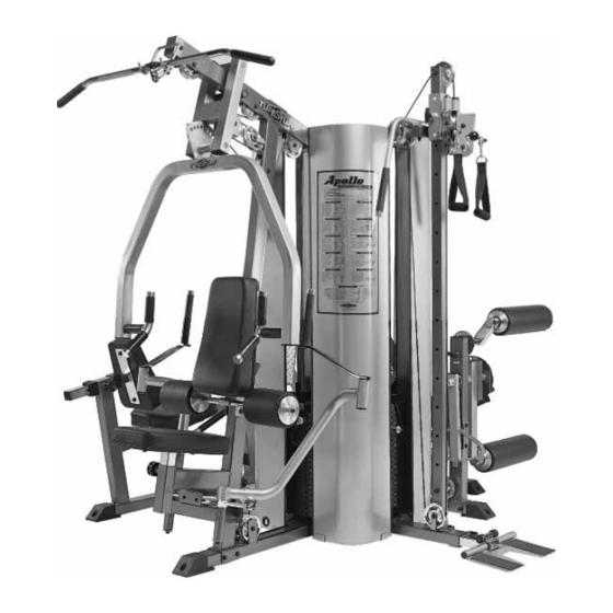
Apollo Modular Gym System
(Base Unit)
Standard
Deluxe
TuffStuff Fitness Equipment, Inc.
1325 E. Franklin Avenue
Pomona, CA 91766, USA
Ph: 909-629-1600 Fax: 909-629-4967
E-mail: service@tuffstuff.net Net: www.tuffstuff.net
A
'
P
MERICA
S
REMIER
E
E
XERCISE
QUIPMENT
M A N U A L
91 1/2"
L 103" W 91 1/2" H 84
103"
Apollo Base Unit Rev1
Revision Date 11-13-2007
Advertisement
Table of Contents

Related Manuals for TuffStuff Apollo


Summary of Contents for TuffStuff Apollo
- Page 1 Vertical Multi-Press Station Pg. 22 Mid Row Station Pg. 24 Leg Developer Station Pg. 26 Maintenance - Pg. 29 - Pg. 30 Warranty - Back Page 103" Apollo Modular Gym System (Base Unit) Standard 91 1/2" Deluxe L 103” W 91 1/2” H 84 TuffStuff Fitness Equipment, Inc.
- Page 2 Unit. assembly or in having to disassemble parts later. 2. Consider the complete surface area of the Apollo Modular Gym 2. During the assembly of this unit you will be instructed to leave System. Use the overhead view on the front page for designing some Hex Head Cap Screws loosely fastened.
-
Page 3: Safety Precautions
Replacement Assembly Instructions and labels are available from your local Tuff Stuff retailer. 3. Consult with your physician before beginning any exercise program. Apollo Modular Gym System (Base Unit) - Page 4 Note: Depending on what optional Stations your system may in- clude, the bottom connectors of these stations (Ab/Back, Inner Outer Thigh, Multi-Press) can be attach to the Weight Stack Frame (#53) as described above. Apollo Modular Gym System (Base Unit)
- Page 5 Locate the four Top Plate Selector Bars (#58) and assemble Plates (#56) over the Guide Rods (#10). Repeat the same process for Magnetic Selector Pins W/Coil 3/8 X 4 (#31) in the position as shown the other three stations. above. Apollo Modular Gym System (Base Unit)
- Page 6 (#43), two Hex Head Cap Screws 3/8-16 X 3 1/4 (#101), four Flat Washers SAE 3/8” (#93), and two Nylon Insert Lock Nuts 3/8-16 (#119). Next, repeat the same procedure for the Leg Press Station. Apollo Modular Gym System (Base Unit)
- Page 7 Next, attach another Pulley 4 1/2 Rd (#67-Labeled A6) to the Front Up- right (#16) using one Hex Head Cap Screw 3/8-16 X 2 1/2 (#99), two Flat Washers SAE 3/8” (#93), and one Nylon Insert Jam Lock Nut 3/8- 16 (#118). Apollo Modular Gym System (Base Unit)
- Page 8 Repeat the same procedure for the Right Pec Dec Arm (#36). Note: It is recommended to grease both axles of the Left and Right Pec Dec Arms (#35, #36) with multi-purpose grease prior to assembling. Apollo Modular Gym System (Base Unit)
- Page 9 Bar Selector Housing (#41) and through the Press Bar (#42). 8 1/8 (#39) and apply four 1” Rd. Silver Mylar Decals (#77–Not shown). These decals are used to hide and protect the ends of the axles. Apollo Modular Gym System (Base Unit)
- Page 10 3/4 (#97), two Flat Washers SAE 3/8” (#93), and one Nylon Insert Jam Lock Nut 3/8-16 (#118). Loosely Fasten: Do not completely fasten this hardware as- sembly at this time, as it will be completely fasten once the ca- bles have been adjusted. Apollo Modular Gym System (Base Unit)
- Page 11 Note: Refer to the Cable Mapping Diagram on fold-out page 21 Note: Refer to the Cable Mapping Diagram on fold-out page 21 for further detailed illustration of the Lat Cable (#22) routing. for further detailed illustration of the Lat Cable (#22) routing. Apollo Modular Gym System (Base Unit)
- Page 12 Lat Cable (#22) routing. Loosely Fasten: Do not completely fasten this hardware as- sembly at this time, as it will be completely fasten later in the assembly process to obtain proper cable tension. Apollo Modular Gym System (Base Unit)
- Page 13 Note: Refer to Fig. C on fold-out page 21 for further clarification Note: Refer to the Cable Mapping Diagram on fold-out page 21 of this hardware assembly. for further detailed illustration of the Pec Dec Cable (#37) routing. Apollo Modular Gym System (Base Unit)
- Page 14 Back Pad Bracket (#2). Next, secure the Foot Roll Tube 1 X 27 (#15) Lock Washers 3/8” (#152), and two Chrome Washers 3/8 X 1 1/2 (#74). to the Adjustable Back Pad Bracket (#2) using one Set Screw 1/4-20 X 1/4 (#147). Apollo Modular Gym System (Base Unit)
- Page 15 Connect the Lat Bar 48” (#111) to the Lat Cable (#22) using the Snap Link (#145). Rest the Lat Bar 48” (#111) onto the Lat Bar Holder (#21), when not in use. Apollo Modular Gym System (Base Unit)
- Page 16 Next, insert the axle of the Circular Plate (#11) into the receptacle of the Pivot Arm (#38). Then, insert the axle of the Circular Plate (#11) with the captive Pivot Arm (#38) into the bearing housing of the Leg Extension Front Frame (#27). Apollo Modular Gym System (Base Unit)
- Page 17 (#28) using two Hex Head Cap Screws 3/8-16 X 3 1/4 (#101), four Flat Washers SAE 3/8” (#93), and two Nylon Insert Lock Nuts 3/8-16 (#119). Fully Fasten: Proceed to align and fully fasten this hardware assembly and the assembly described in FIG. 54. Apollo Modular Gym System (Base Unit)
- Page 18 Chrome Washer 3/8 X 1 1/2 (#74). Next, attach the Swivel Foam Roll Tube (#47) to the Pivot-Arm (#38) using one Button Head Socket Cap Screw 3/8-16 X 1 (#71), one Split Lock Washer 3/8” (#152), and one Chrome Washer 3/8 X 1 1/2 (#74). Apollo Modular Gym System (Base Unit)
- Page 19 Note: Refer to the Cable Mapping Diagram on fold-out page 26 Note: Refer to the Cable Mapping Diagram on fold-out page 26 for further detailed illustration of the Leg Extension Cable (#26) for further detailed illustration of the Leg Extension Cable (#26) routing. routing. Apollo Modular Gym System (Base Unit)
- Page 20 Leg Press Station Ab/Back Station Ab/Back Station Single Column Station Inner Outer Thigh Station Inner Outer Thigh Station FIG. 66 Proceed to Assemble two of the four optional attachments to the sides of the unit. Apollo Modular Gym System (Base Unit)
- Page 21 Nylon Insert Lock Nuts 3/8-16 (#119). Repeat the same process for the three other Weight Shields (#50). Note: Refer to the illustrations shown on fold-out page 28 for fur- ther clarification of this hardware assembly. Apollo Modular Gym System (Base Unit)
- Page 22 Maintenance TuffStuff Basic Strength Equipment Safety and General Maintenance All TUFFSTUFF strength equipment is designed and manufactured to offer maximum, long-life service with minimal maintenance. However, safety inspection and routine maintenance in your facility should be the upmost importance in your daily operation. Information presented in these pages will serve as a basic guideline to design your own inspection procedures.
- Page 23 Bearing and linear bearings systems have advanced over the years but they must be maintained on a regu- lar basis if you expect them to last and perform effi ciently. TuffStuff uses only the highest quality bearings and linear motion components that are virtually trouble-free but requires the regular preventive maintenance to insure long-lasting performance.
- Page 24 L I M I T E D W A R R A N T Y TuffStuff warrants to the original purchaser only that TuffStuff equipment will be free from defects in material and workmanship. The warranty and remedies set forth herein are conditioned upon proper storage, installation, use, maintenance and conformance with any recommendations of TuffStuff.
- Page 25 BNH1650 METAL HINGE BNH0046 NYLON PULLEY 3/8 X 4 1/2 BNH0506 10 LB TOP PLATE W/ADJ SLTR BAR 19 BLK WTS BNH1982 NYLON BALL 1 3/4 X 5/16 BNH0047 Apollo Modular Gym System (Base Unit) PARTS LIST Fold-Out Page 20...
- Page 26 1/2” into the threaded socket of the Selector Bar (#58) once the cable adjustment has been completed. FIG. C Note: Some parts have been cut away for clarity. Unfold Fold-Out Page 21 Cable Mapping Diagram Vertical Multi-Press Station Apollo Modular Gym System (Base Unit) Page...
- Page 27 Apollo Modular Gym System (Base Unit) Exploded View Diagram Vertical Multi-Press Station Fold-Out Page 22...
- Page 28 1/2” into the threaded socket of the Selector Bar (#58) once the cable adjustment has been completed. FIG. C Note: Some parts have been cut away for clarity. Unfold Fold-Out Page 23 Cable Mapping Diagram Mid Row Station Apollo Modular Gym System (Base Unit) Page...
- Page 29 Apollo Modular Gym System (Base Unit) Exploded View Diagram Mid Row Station Fold-Out Page 24...
- Page 30 Selector Bar (#58) once the cable adjustment has been completed. Note: Some parts have been cut away for clarity. Unfold Fold-Out Page 25 Cable Mapping Diagram Leg Developer Station Apollo Modular Gym System (Base Unit) Page...
- Page 31 Apollo Modular Gym System (Base Unit) Exploded View Diagram Leg Developer Station Fold-Out Page 26...
- Page 32 Unfold Fold-Out Page 27 Apollo Modular Gym System (Base Unit) Page...
Need help?
Do you have a question about the Apollo and is the answer not in the manual?
Questions and answers