
Related Manuals for Metrix MX 26


Summary of Contents for Metrix MX 26
- Page 1 MX 26 MULTIMETRE NUMERIQUE DIGITAL MULTIMETER DIGITAL MULTIMETER MULTIMETRO DIGITALE MULTIMETRO DIGITAL User's manual page 15 Chapter Copyright © 906129650 - Ed. 5 - 03/13...
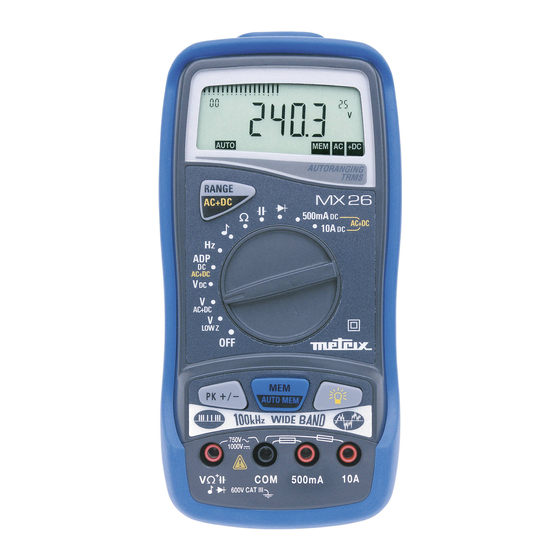
- Page 2 Interface optique RS232 RS232 optical interface optische Schnittstelle RS232 Interfacia ottica RS232 Interfaz optica RS232 MX 26 Multimètre digital portable 5000 points, avec entrées courant...
- Page 3 LEGENDE / LEGEND / BESCHREIBUNG / LEGENDA / LEYENDA 1 Borne d’entrée (positions 12 à 20) 12 Mesure de tensions AC: gammes 5 V à 750 V (basse impédance) 2 Entrée de référence du multimètre 13 Mesure de tensions AC+DC: gammes 5 V à...
-
Page 4: Table Of Contents
Chapter II USER’S MANUAL CONTENTS GENERAL INSTRUCTIONS ........................16 1.1. Precautions and safety measures ....................16 1.1.1. Preliminary...........................16 1.1.2. During use ...........................16 1.1.3. Symbols............................17 1.1.4. Instructions ..........................17 1.2. Protection mechanisms ........................18 1.3. Safety mechanisms .........................18 1.4. Warranty............................18 1.5. Maintenance and metrological verification ..................18 1.6. -
Page 5: General Instructions
Chapter II GENERAL INSTRUCTIONS You are the new owner of a 5000 ct portable digital multimeter and we thank you for your choice. This instrument complies with the specification set out in the IEC 61010-1 + A1 + A2, concerning safety requirements for electronic measuring apparatus. To get the best service from this instrument, read carefully this user's manual and respect the detailed safety precautions. -
Page 6: Symbols
Chapter II ∗ When the multimeter is linked to measurement circuits, do not touch unused terminals. ∗ When the range of the value to be measured is unknown, check that the range initially set on the multimeter is the highest possible or, wherever possible, choose the autoranging mode. -
Page 7: Protection Mechanisms
Chapter II 1.2. Protection mechanisms This instrument is fitted with various protection mechanisms : ∗ Varistor protection for limiting transients of over 1100 V at the VΩ terminal, particularly 6 kV pulse streams as defined by the French standard IEEE 587. ∗... -
Page 8: Description
Chapter II DESCRIPTION This compact multimeter is a self-contained with an appropriate mechanical construction, enables hand-held version, with a protective elastomer case. It is designed for a high degree of user safety, maximum protection and unrivalled performance. 2.1. Selector switch This multimeter is a standalone, hand-held professional measuring instrument, capable of measuring the following quantities (accessed by the twelve-position rotary selector switch): ∗... -
Page 9: Getting Started
Chapter II GETTING STARTED 3.1. Connecting the test leads Connect the black lead to the COM socket (for all measurements). Depending on the position of the selector switch, connect the red lead as follows: Rotary selector switch position Input terminal V Ω... -
Page 10: Battery Self-Test
Chapter II 3.5.2. Battery self-test When the BAT indication appears on the display, the instrument still has approximately 12 hours of operation, but specifications can no longer be guaranteed. Replace the battery. 3.5.3. Replacing the battery or fuses Caution ! Disconnect test leads from any circuit under test, turn the meter off and remove test leads from the input terminals . -
Page 11: Function Description
Chapter II FUNCTION DESCRIPTION 4.1. RANGE / AC+DC key The RANGE key is operative in following positions of the selector switch : , Ω, , Hz. LOW Z AC+DC This key makes it possible : • In AUTO (Autoranging) mode to switch to MANUAL mode (short press). •... -
Page 12: Adc / 10 Aac+Dc Position
Chapter II 4.1.3. 10 A / 10 A Position AC+DC 10 A DC current measurement (Range 10 A AC+DC key 10 A AC+DC The AC+DC sign AC+DC current measurement (TRMS) appears on the display. (Range 10 A AC+DC AC+DC key 4.2. -
Page 13: Software Kit (Optional)
Chapter II SOFTWARE KIT (optional) Connection of the kit and installation of the SX-DMM software : With the software kit option, the multimeter can interface directly with a computer or PC: 1. Connect the optical plug at the top of the shockproof sheath. A mechanical fail-safe device is provided on the left-hand side to prevent connection the wrong way round. -
Page 14: Technical Specifications
Chapter II TECHNICAL SPECIFICATIONS 6.1. General Only the values assigned tolerances or given limits are guaranteed values. Values without tolerances are given for information only, without guarantee (standard NFC 42670). The measurement errors must be considered in an environment of reference temperature (refer to § 6.2.11). -
Page 15: Dc Current
Chapter II 6.2.3. DC current (∗) Selector switch position Ranges Accuracy Max volt. drop Protection Fuses Resolution 500 mA 500 mA 0.3 % R + 2 D < 600 mV 600 V F1 + F2 100 µA (∗∗) 10 A 1 % R + 2 D <... -
Page 16: Capacitance
Chapter II 6.2.6. Capacitance Note Discharge all capacitors before taking measurements. Selector switch Ranges Accuracy Measurement Max measurement Protection Resolution (∗) position current time 50 nF 100 nA < 1 s 10 pF 500 nF 1 µA < 1 s 100 pF 5 µF 10 µA... -
Page 17: General Information
Chapter II 6.2.10. General information Mechanical Dimensions 170 x 80 x 35 mm Weight (inc. battery) 285 g Casing and circuit self-extinguishing materials Packaging Dimensions 230 x 155 x 65 mm Weight 385 g Power supply Power requirements single 9 V alkaline battery (6LF22) Low battery indication BAT is displayed when the battery voltage drops below operating voltage... -
Page 18: Accessories
Chapter II 6.3. Accessories 6.3.1. Supplied with the multimeter One set of test leads with safety probes One 6LF22 9 V battery AL0042 One user’s manual 906129650 Protective elastomer case with RS232 window HX0010 6.3.2. Optional Communication kit SX-DMMK Acquisition Software (part. nr. SX-DMMC) RS232 lead (DB9F) (part.
Need help?
Do you have a question about the MX 26 and is the answer not in the manual?
Questions and answers