Table of Contents
Advertisement
Quick Links
Advertisement
Table of Contents

Related Manuals for Black Horse Model CORSAIR


Summary of Contents for Black Horse Model CORSAIR
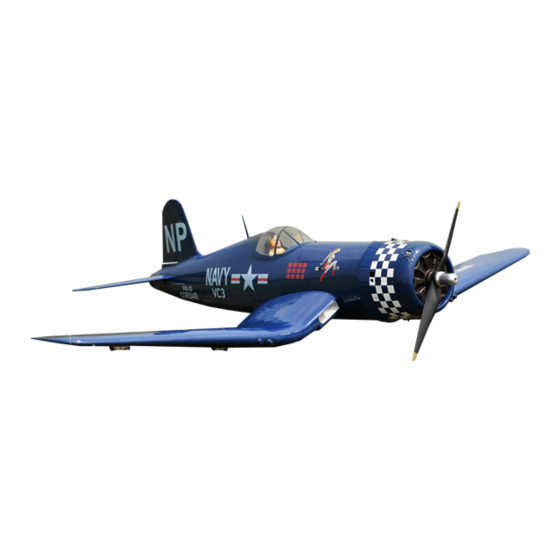
- Page 1 Instruction Manual book SPECIFICATION Wingspan : 2,280 mm 89.76 in. Length 1,800 mm 70.87 in. Weight 8.4 kg 18.48 Lbs. Radio 06 channels.
-
Page 2: Parts List
Instruction Manual ITEM CODE: BH64. This instruction manual is designed to help you build a great flying aeroplane. Please read this manual thoroughly before starting assembly of your CORSAIR. Use the parts listing below to identify all parts. WARNING Please be aware that this aeroplane is not a toy and if assembled or used incorrectly it is capable of causing injury to people or property. -
Page 3: Safety Precaution
CORSAIR Instruction Manual ITEM CODE: BH64. Caution: this model is not a toy! If you are a beginner to this type of powered model, please ask an experienced model flyer for help and support. If you attempt to operate the model without knowing what you are doing you could easily injure yourself or somebody else. - Page 4 CORSAIR Instruction Manual ITEM CODE: BH64. REPLACEMENT LARGE PARTS A. Cowling. F. Aluminium wing dihedral brace. B. Wing panel. F1. Aluminium tube Horizontal stabilizer. C. Fuselage. G. Decal sheets. D. Horizontal stabilizer. K. Pilot E. Rudder REPLACEMENT SMALL PARTS 3x15mm...
-
Page 5: Installing The Aileron Servos
CORSAIR Instruction Manual ITEM CODE: BH64. Tray servo. I. AILERON. 2) Using a modeling knife, remove the cov- ering at possition show below. 1.INSTALLING THE AILERON SERVOS. 1) Install the rubber grommets and brass eyelets onto the aileron servos. -
Page 6: Installing The Aileron Linkages
CORSAIR Instruction Manual ITEM CODE: BH64. Electric wire A+B Epoxy PLUS glue Thread A+B Epoxy PLUS glue 5. Instal servo tray with aileron servo into the wing as same as picture below. 2x10mm. Secure Elevator control horn Repeat the procedure for the other wing half. -
Page 7: Installing The Flap Servos
CORSAIR Instruction Manual ITEM CODE: BH64. 3x10mm tray servo Flap Secure. Electric Bottom side. wire Thread Flap Aileron. Repeat the procedure for the other wing half. II. FLAP. 1.INSTALLING THE FLAP SERVOS. 2x10mm. Secure. Flap Flap Flap Bottom side. - Page 8 CORSAIR Instruction Manual ITEM CODE: BH64. 3x10mm Secure 2.INSTALLING THE FLAP CONTROL HORN. Flap control horn Bottom side. A+ B Epoxy glue. Aileron Flap Repeat the procedure for the other wing half. INSTALLING SERVO WHEEL DOOR. Control horn of the flap Repeat the procedure for the other wing half.
- Page 9 CORSAIR Instruction Manual ITEM CODE: BH64. INSTALLING AIR RETRACTABLE LANDING GEAR. 3x15mm 3x15mm Air tank 3 way connector Valve one way . Valve control. Air line set. spring.
- Page 10 CORSAIR Instruction Manual ITEM CODE: BH64. C/A glue C/A glue 3x15mm 5x45mm 3x15mm Secure.
- Page 11 CORSAIR Instruction Manual ITEM CODE: BH64. 5x45mm C/A glue secure.
-
Page 12: Installing The Engine Mount
CORSAIR Instruction Manual ITEM CODE: BH64. INSTALLING THE ENGINE MOUNT. See pictures below: Drill a hole 4mm diameter Secure INSTALLING THE ENGINE. 5x60mm Bottom side. Aileron Flap Repeat the procedure for the other gear half. - Page 13 CORSAIR Instruction Manual ITEM CODE: BH64. INSTALLING THE THROTTLE PUSHROD 1. Install one adjustable metal connector through the third hole out from the center of Secure one servo arm, enlarge the hole in the servo arm using a 2mm drill bit to accommodate the servo connector.
-
Page 14: Installing The Stopper Assembly
CORSAIR Instruction Manual ITEM CODE: BH64. end of the line to the weighted clunk and the other end to the nylon pick up tube in the stop- per. 3) Carefully bend the second nylon tube up at a 45 degree angle (using a cigarette Throttle cable. - Page 15 CORSAIR Instruction Manual ITEM CODE: BH64. 6) When satisfied with the alignment of the stopper assembly tighten the 3mm x 20mm machine screw until the rubber stopper ex- pands and seals the tank opening. Do not over tighten the assembly as this could cause the tank to split.
- Page 16 CORSAIR Instruction Manual ITEM CODE: BH64. Pushrod choke. 2) While keeping the back edge of the cowl flush with the marks, align the front of the cowl with the crankshaft of the engine. The front of the cowl should be positioned so the crankshaft is in nearly the middle of the cowl opening.
- Page 17 CORSAIR Instruction Manual ITEM CODE: BH64. Drill a hole 2mm. Left side Left side 4) Install the muffler and muffler extension onto the engine and make the cutout in the Secure cowl for muffler clearance. Connect the fuel and pressure lines to the carburetor , muffler and fuel filler valve.
-
Page 18: Horizontal Stabilizer
CORSAIR Instruction Manual ITEM CODE: BH64. HORIZONTAL STABILIZER. Tray servo ELEVATOR SERVO INSTALLATION. 1. Install the rubber grommets and brass collets into the elevator servo. Test fit the servo into the servo tray. 2. Mount the servo to the tray using the ... -
Page 19: Elevator Control Horn Installa- Tion
CORSAIR Instruction Manual ITEM CODE: BH64. 2x10mm Elevator Secure. control horn ELEVATOR PUSHROD INSTALLATION. Elevator pushrod install as same as the way of aileron pushrod. ELEVATOR CONTROL HORN INSTALLA- 40mm 3x10mm TION. Elevator control horn install as same as the way of aileron control horn. - Page 20 CORSAIR Instruction Manual ITEM CODE: BH64. Top side. B o t t o m side. Aluminium tube 12 mm Elevator pushrod 243 mm Elevator pushrod Bottom side. 4x15mm...
-
Page 21: Rudder Servo Installation
CORSAIR Instruction Manual ITEM CODE: BH64. Rudder Installation See picture below. Secure. Bottom side. Top side. RUDDER SERVO INSTALLATION. Rudder servo install as same as method of elevator servo. See picture below: Rudder Servo Rudder Servo... -
Page 22: Mounting The Tail Wheel Bracket
CORSAIR Instruction Manual ITEM CODE: BH64. Aluminium Open. Aluminium. MOUNTING THE TAIL WHEEL BRACKET. 3x15mm Bottom side. 3x15mm... - Page 23 CORSAIR Instruction Manual ITEM CODE: BH64. Secure Secure. Cut. A+B Epoxy PLUS glue. Top side. Secure.
- Page 24 CORSAIR Instruction Manual ITEM CODE: BH64. valve control servo. Air tank Air supply Valve one way INSTALLING SERVO USING FOR VALVE Right main CONTROL gear wing Left main gear wing Valve control valve control servo. Valve control...
- Page 25 CORSAIR Instruction Manual ITEM CODE: BH64.
-
Page 26: Installing The Switch
CORSAIR Instruction Manual ITEM CODE: BH64. INSTALLING THE SWITCH. 1) Cut out the switch hole using a modeling knife. Use a 2mm drill bit and drill out the two mounting holes through the fuselage side. -
Page 27: Wing Attachment
CORSAIR Instruction Manual ITEM CODE: BH64. 4. Using a 2mm drill bit, drill a hole through 2. Attach the aluminium tube into the the side of the fuselage, near the receiver , for fuselage. -
Page 28: Installing Cockpit Fuselage
CORSAIR Instruction Manual ITEM CODE: BH64. Secure. A+B Epoxy P L U S glue. A+ B Epoxy PLUS glue Secure. INSTALLING COCKPIT FUSELAGE . - Page 29 CORSAIR Instruction Manual ITEM CODE: BH64. Secure. C/A glue Secure. Antenna See picture wing attach to fuselage. Installing the fuselage hatch as same as pic- ture below. Top side. Secure.
- Page 30 CORSAIR Instruction Manual ITEM CODE: BH64. C/A glue R e m o v e covering Air cool plastic parts. C/A glue...
- Page 31 CORSAIR Instruction Manual ITEM CODE: BH64. BALANCING. 1) It is critical that your airplane be bal- anced correctly. Improper balance will cause your plane to lose control and crash. THE CENTER OF GRA VITY IS LOCA TED...
-
Page 32: Control Throws
Rudder : 20mm right 20mm left 6) Properly balance the propeller. 20mm 20mm We wish you many safe and enjoy- able flights with your CORSAIR. 35mm 15mm 15mm 20mm 20mm...
Need help?
Do you have a question about the CORSAIR and is the answer not in the manual?
Questions and answers