Table of Contents
Advertisement
Quick Links
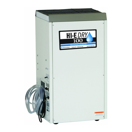
HI-E Dry 100
HI-E Dry 100
Installation, Operation and Maintenance Instructions
Installation, Operation and Maintenance Instructions
– Read and Save These Instructions –
– Read and Save These Instructions –
This manual is provided to acquaint you with
the humidity control device so that installation,
operation and maintenance can proceed
successfully. Ultimate satisfaction depends
on the quality of installation and a thorough
understanding of this equipment. The humidity
control device is built around tested engineering
principles and has passed a thorough inspection
for quality of workmanship and function.
HI-E Dry 100:
• Controlled by a dehumidistat with settings
from 20 to 80 percent relative humidity and a
positive "on" and "off" setting.
• Contains a blower switch that permits
continuous blower operation independent of
dehumidification.
• Portable and provided with four casters.
• Contains an internal condensate pump capable
of lifting condensate 17 feet and 20 feet of
condensate hose.
• Wiring is through a factory installed six foot
power cord; 115 volt with ground.
• Environmentally friendly R410A refrigerant.
quest
quest
Specifications subject to change without notice.
Water Removal Rates (Pints/Day)
172 pints
129 pints
110 pints
113 pints
83 pints
94 pints
64 pints
67 pints
25 pints
4201 Lien Rd.
Madison, WI 53704
www.QuestProtect.com
1
90˚F, 90%
80˚F, 80%
80˚F, 60% (AHAM)
70˚F, 80%
70˚F, 60%
60˚F, 80%
60˚F, 60%
50˚F, 80%
50˚F, 60%
Toll-Free 1-800-533-7533
sales@QuestProtect.com
TS-598
04/14
Advertisement
Table of Contents

Related Manuals for Quest Engineering HI-E Dry 100


Summary of Contents for Quest Engineering HI-E Dry 100
- Page 1 HI-E Dry 100 HI-E Dry 100 Installation, Operation and Maintenance Instructions Installation, Operation and Maintenance Instructions – Read and Save These Instructions – – Read and Save These Instructions – This manual is provided to acquaint you with the humidity control device so that installation, operation and maintenance can proceed successfully.
-
Page 2: Table Of Contents
HI-E DRY 100 Installation, Operation and Maintenance Instructions Table of Contents 1. Specifications ..............4 2. Installation ..............4 2.1 Location ..............4 2.1A In humid area, no ducting ......5 2.1B In humid area, duct inlet and/or outlet ...5 2.1C In remote area, duct inlet & outlet ....5 2.1D In remote area, duct outlet only .....5 2.1E In remote area, duct inlet only ......5 2.2 Electrical Requirements ..........5 2.3 Condensate Removal ..........6 2.4 Ducting ..............6 2.4A Optional Ducting ......... 6 2.4B Ducting for Dehumidification ......6 2.4C Ducting for Fresh Air . -
Page 3: Safety Precautions
HI-E DRY 100 Installation, Operation and Maintenance Instructions Safety Precautions Read the installation, operation and maintenance instructions carefully before installing and using this unit. Proper adherence to these instructions is essential to obtain maximum benefit from your HI-E Dry 100 humidity control device. READ AND SAVE THESE INSTRUCTIONS • It is designed to be installed INDOORS ONLY. • DO NOT use the HI-E Dry 100 as a bench or table. • Avoid discharging the air directly at people. quest quest quest quest 1-800-533-7533 www.QuestProtect.com Asset Protection and IAQ Solutions sales@QuestProtect.com... -
Page 4: Specifications
HI-E DRY 100 Installation, Operation and Maintenance Instructions 1. Specifications Part Number 4029730 Power 110-120 VAC 6.4 amps Kilowatts 0.70 (80° 60%) Blower 275 CFM Capacity (24 hrs.) 110 pints (80°, 60%) Temp. Range 33°F–110°F Warranty 5 Year Limited Dimensions Unit Shipping Width 20” 25” Height 36” 41” Depth 17” 24” Weight 110 Lb 125 Lb Minimum Performance at Set Conditions Intake Air 70° 60%... -
Page 5: A In Humid Area, No Ducting
HI-E DRY 100 Installation, Operation and Maintenance Instructions 2.1A In Humid Area, No Ducting The simplest installation is to place the HI-E Dry 100 in the humid area with no ducting. The air inlet on top & outlet on the side must be at least 1’ from walls and other obstructions to air flow. 2.1B In Humid Area, Duct inlet and/or Outlet If the humid area is very large or has high ceilings, dehumidification can be improved by adding an inlet and/or outlet duct to circulate and destratify stagnant areas. For a large area, add inlet or outlet ducting to create flow across the area’s greatest length. For areas with ceilings higher than 12’, use an inlet duct to draw warm, moist air from near the ceiling. See section 2.4 for attaching duct collars & ducting. 2.1C In Remote Area, Duct Inlet & Outlet It is often desirable, especially in finished areas, to install the HI-E Dry 100 in an adjacent equipment room or unfinished area. Air is transferred between the humid room and the unit via ducting. The factory mounted humidity control on the HI-E Dry 100 cabinet may not sense the humidity in the humid room accurately enough with this installation method. If so, an additional humidity control can be mounted... -
Page 6: Condensate Removal
HI-E DRY 100 Installation, Operation and Maintenance Instructions 2.3 Condensate Removal The HI-E Dry 100 is equipped with a condensate pump to remove the water that is condensed during dehumidification. This allows the condensate to be disposed of at a distant location, or to be pumped to a level above the HI-E Dry 100. The condensate pump is mounted inside the HI-E Dry 100 as an integral part of the unit. If the condensate must be pumped more than 18 feet above the unit, a second pump must be added to relay the condensate. 2.4 Ducting 2.4A Optional Ducting An inlet shroud with a 8” round collar and an 8” round exhaust collar are available from the factory that will allow round ducting to be attached to the inlet and/or outlet of the HI-E Dry 100. 2.4B Ducting for Dehumidification Ducting the HI-E Dry 100 as mentioned in sections 2.1B-2.1E requires consideration of the following points. Duct Sizing: For total duct lengths up to 25’, use a minimum 8” diameter round or equivalent rectangular. For longer lengths, use a minimum 10” diameter or equivalent. Grills or diffusers on the duct ends must not excessively restrict air flow. Isolated Areas: Effective dehumidification may require that ducting be branched to isolated, stagnant areas. Use 6” diameter branch ducting to each of two or three areas; use 4” to each of four or more areas. 2.4C Ducting for Fresh Air Fresh air can be brought into the structure continuously by connecting a duct from outside to the HI-E Dry 100 inlet and by turning on the fan switch. Advantages of this form of ventilation include: 1. Outside air is filtered before entering the building. -
Page 7: Fan Switch
5. Service CAUTION: Servicing the HI-E Dry 100 with its high-pressure refrigerant system and high voltage circuitry presents a health hazard which could result in death, serious bodily injury, and/or property damage. Only qualified service people should service this unit. -
Page 8: Troubleshooting
No dehumidification, neither blower nor compressor run with fan switch OFF. 1. Unit unplugged or no power to outlet. 2. Humidity control set too high or defective (Sec. 3.1 & 5.9) Figure 3: Refrigeration system of HI-E Dry 100 3. Loose connection in internal wiring. Some dehumidification, blower runs continuously but compressor only runs sporadically with fan switch OFF. 1. Unit is in defrost cycle (Sec. 3.3 & 5.10). -
Page 9: Refrigerant Charging
HI-E DRY 100 Installation, Operation and Maintenance Instructions Unit removes some water but not as much as expected. 1. Air temperature and/or humidity have dropped. 2. Humidity meter and/or thermometer used are out of calibration. 3. Unit has entered defrost cycle (Sec. 3.3 & 5.10). 4. Air filter dirty (Sec. 4.1). 5. Defrost timer incorrectly set for conditions (Sec. 3.3 & 5.10). 6. Defective defrost thermostat (Sec. 5.10). 7. Low refrigerant charge (Sec. 5.4). 8. Air leak such as loose cover. 9. Defective compressor (Sec. 5.6). 10. R estrictive ducting (Sec. 2.4). Pump does not pump water. -
Page 10: Compressor/Capacitor Replacement
HI-E DRY 100 Installation, Operation and Maintenance Instructions 5.6 Compressor/Capacitor Replacement This compressor is equipped with a two terminal external overload, run capacitor, but no start capacitor or relay (see Fig. 4). CAUTION-ELECTRICAL SHOCK HAZARD: Electrical power must be present to perform some tests; these tests should be performed by a qualified service person. 5.6A Checking Compressor Motor Circuits Perform the following tests if the blower runs but the compressor does not with the humidity control ON. -
Page 11: C Replacing A Compressor
HI-E DRY 100 Installation, Operation and Maintenance Instructions The following procedure is effective only if the system is monitored after replacing the compressor to insure that the clean up was complete. 1. This procedure assumes that the previously listed compressor motor circuit tests revealed a shorted or open winding. If so, cautiously smell the refrigerant from the compressor service port for the acid odor of a burn out. WARNING: The gas could be toxic and highly acidic. If no acid odor is present, skip down to the section on changing a non-burn out compressor. -
Page 12: Humidity Control
HI-E DRY 100 Installation, Operation and Maintenance Instructions 5.8 Humidity Control The humidity control is an adjustable switch that closes when the relative humidity of the air in which it is located rises to the dial set point. It opens when the RH drops 4 to 6% below the set point. 5.9 Defrost Thermostat & Timer The defrost thermostat is attached to the refrigerant suction tube between the accumulator and compressor. If the low side refrigerant temperature drops due to excessive frost formation on the evaporator coil, the thermostat opens. The compressor is then cycled off and on by the defrost timer. The blower will continue to run, causing air to flow through the evaporator coil and melt the ice when the compressor is off. When the air temperature and/or humidity increase, the evaporator temperature will rise and the thermostat will close to end the defrost cycle. 5.10 Condensate Pump Condensate is automatically pumped when the water level in the pump’s reservoir rises to close the float switch. If the pump is unable to empty its reservoir due to a pump failure or blocked condensate hose, a pump safety float switch is triggered before the reservoir overflows. The switch turns off the compressor via its relay. To replace the condensate pump: 1. Unplug the unit & remove the front cover. 2. Disconnect the 2 hoses from the pump. 3. Cut the pump lead wires near the old pump. 4. Remove the 2 nuts from the unit side that hold the pump to the side. -
Page 13: Wiring Diagram
MOTOR RELAY CAPACITOR COMPRESSOR PART NO. REV. Made in U.S.A. 4033549 Therma-Stor LLC, Madison, WI 800-533-7533 or Local 608-237-8400 www.thermastor.com Figure 4: Electrical Schematic of HI-E Dry 100 quest quest quest quest 1-800-533-7533 www.QuestProtect.com Asset Protection and IAQ Solutions sales@QuestProtect.com... -
Page 14: Service Parts List
HI-E DRY 100 Installation, Operation and Maintenance Instructions 7. Service Parts: HI-E Dry 100 Humidity control device ITEM PART NO. QTY. DESCRIPTION 4022254 Accumulator 4021475 Air Filter, Pleated, 2” x 16” x 20” 4021468 Air Filter, Foam Element 4026930 Blower, w/Capacitor, 115V 4028233 Capillary Tubes 4032371 Compressor Kit (includes Overload), Panasonic (2R12S3R126A-6A) 4029169 Compressor Overload (not shown) 4033032-05 Compressor Run Capacitor, 45 MFD, 370V 4034097 Condensate Pump 4028226... -
Page 15: Filter Installation Instructions
HI-E DRY 100 Installation, Operation and Maintenance Instructions 8. Filter Installation Instructions To prevent damaging the foam filter, place it “grid side up” on top of the pleated filter and slide them both into the filter slot. quest quest quest quest 1-800-533-7533 www.QuestProtect.com Asset Protection and IAQ Solutions sales@QuestProtect.com... -
Page 16: Warranty
HI-E Dry 100 Installation, Operation and Maintenance Instructions HI-E DRY 100 Installation, Operation and Maintenance Instructions HI-E Dry 100 Humidity Control Device Limited Warranty Warrantor: Therma-Stor LLC 4201 Lien Rd Madison, WI 53704 Telephone: 1-800-533-7533 Who Is Covered: This warranty extends only to the original end-user of the HI-E Dry 100 humidity control device, and may not be assigned or transferred. Year One: Therma-Stor warrants that, for one (1) year the HI-E Dry 100 humidity control device will operate free from any defects in materials and workmanship, or Therma-Stor will, at its option, repair or replace the defective part(s), free of any charge. Year(s) Two Through Five: Therma-Stor further warrants that for a period of five (5) years, the condenser,...
Need help?
Do you have a question about the HI-E Dry 100 and is the answer not in the manual?
Questions and answers