Lexmark X862de Service Manual
Hide thumbs
Also See for X862de:
- Service manual (562 pages) ,
- User manual (315 pages) ,
- Technical reference manual (106 pages)
Table of Contents
Advertisement
Quick Links
Revision: November 9, 2011
™
Lexmark
X860de, X862de, and X864de MFP
7500-432, -632, and -832
• Table of contents
• Start diagnostics
• Safety and notices
• Trademarks
• Index
Lexmark and Lexmark with diamond design are
trademarks of Lexmark International, Inc., registered
in the United States and/or other countries.
Advertisement
Table of Contents

Related Manuals for Lexmark X862de


Summary of Contents for Lexmark X862de
- Page 1 X860de, X862de, and X864de MFP 7500-432, -632, and -832 • Table of contents • Start diagnostics • Safety and notices • Trademarks • Index Lexmark and Lexmark with diamond design are trademarks of Lexmark International, Inc., registered in the United States and/or other countries.
- Page 2 Lexmark and Lexmark with diamond design are trademarks of Lexmark International, Inc., registered in the United States and/or other countries. MarkNet is a trademark of Lexmark International, Inc., registered in the United States and/or other countries.
-
Page 3: Table Of Contents
7500-432, -632, and -832 Table of contents Previous Notices ............. . xv Laser notice . - Page 4 7500-432, -632, and -832 ADF feed motor assembly ............1-42 Previous ADF registration motor .
- Page 5 7500-432, -632, and -832 243.00 Sensor (pre-feed) on jam (tray 3 media feed) ........2-62 Previous 243.01 Sensor (tray 3 feed-out) on jam (tray 3 media feed) .
- Page 6 7500-432, -632, and -832 844.00 Exposure lamp failure ........... .2-136 Previous 844.01 White reference/exposure lamp illumination failure .
- Page 7 7500-432, -632, and -832 2TM/TTM left door assembly open ..........2-175 Previous Duplex left door assembly open .
- Page 8 7500-432, -632, and -832 Scanner manual registration factory defaults ........3-30 Previous Exiting Diagnostics Menu .
- Page 9 7500-432, -632, and -832 Media tray end guide removal ........... . 4-30 Previous Media tray lift gear group removal .
- Page 10 7500-432, -632, and -832 Sensor (fuser exit) removal ............4-103 Previous Fuser unit assembly removal .
- Page 11 7500-432, -632, and -832 Left cover pinch roll assembly removal ......... . . 4-179 Previous ADF feed drive motor assembly removal .
- Page 12 7500-432, -632, and -832 2000-sheet dual input (TTM)—2TM/TTM media transport roll assembly removal ..4-253 Previous 2000-sheet dual input (TTM)—sensor (tray 3 feed-out) removal ......4-254 2000-sheet dual input (TTM)—media feed lift motor removal .
- Page 13 7500-432, -632, and -832 Exit 2 cooling fan removal ............4-338 Previous Component locations .
- Page 14 7500-432, -632, and -832 Assembly 38: 2000-sheet dual input (TTM)—drive and electrical ......7-78 Previous Assembly 39: Duplex outer .
-
Page 15: Notices
7500-432, -632, and -832 Notices Previous Laser notice Next The printer is certified in the U.S. to conform to the requirements of DHHS 21 CFR Subchapter J for Class I (1) laser products, and elsewhere is certified as a Class I laser product conforming to the requirements of IEC 60825-1. - Page 16 7500-432, -632, and -832 Previous Avisos sobre el láser Se certifica que, en los EE.UU., esta impresora cumple los requisitos para los productos láser de Clase I (1) establecidos en el subcapítulo J de la norma CFR 21 del DHHS (Departamento de Sanidad y Servicios) y, en los demás países, reúne todas las condiciones expuestas en la norma IEC 60825-1 para productos láser de Next Clase I (1).
- Page 17 7500-432, -632, and -832 Previous Huomautus laserlaitteesta Tämä kirjoitin on Yhdysvalloissa luokan I (1) laserlaitteiden DHHS 21 CFR Subchapter J -määrityksen mukainen ja muualla luokan I laserlaitteiden IEC 60825-1 -määrityksen mukainen. Next Luokan I laserlaitteiden ei katsota olevan vaarallisia käyttäjälle. Kirjoittimessa on sisäinen luokan IIIb (3b) 5 milliwatin galliumarsenidilaser, joka toimii aaltoalueella 770 - 795 nanometriä.
- Page 18 7500-432, -632, and -832 Previous Next Go Back xviii MFP Service Manual...
-
Page 19: Lithium Warning
7500-432, -632, and -832 Previous Lithium warning CAUTION—POTENTIAL INJURY: There is a danger of explosion if a lithium battery is incorrectly replaced. Replace it only with Next the same or an equivalent type of lithium battery. Do not recharge, disassemble, or incinerate a lithium battery. - Page 20 7500-432, -632, and -832 Previous Sicherheitshinweise • Die Sicherheit dieses Produkts basiert auf Tests und Zulassungen des ursprünglichen Modells und bestimmter Bauteile. Bei Verwendung nicht genehmigter Ersatzteile wird vom Hersteller keine Verantwortung oder Haftung für die Sicherheit übernommen. Next • Die Wartungsinformationen für dieses Produkt sind ausschließlich für die Verwendung durch einen Wartungsfachmann bestimmt.
- Page 21 7500-432, -632, and -832 Previous Informació de Seguretat • La seguretat d'aquest producte es basa en l'avaluació i aprovació del disseny original i els components específics. El fabricant no es fa responsable de les qüestions de Next seguretat si s'utilitzen peces de recanvi no autoritzades. •...
-
Page 22: Preface
7500-432, -632, and -832 Preface Previous Service information for the Lexmark X860de, X862de, and X864de is contained within two service manuals: • MFP Service Manual—Contains specific service information for the MFP and includes the options error codes. Next • Options Service Manual—Contains specific service information for the 2X 500-Sheet Drawer (2TM), High Capacity Feeder, and Finisher. - Page 23 7500-432, -632, and -832 There are several types of caution statements: Previous CAUTION—POTENTIAL INJURY: A caution identifies something that might cause a servicer harm. Next Go Back CAUTION—SHOCK HAZARD: This type of caution indicates there is a danger from hazardous voltage in the area of the product where you are working.
- Page 24 7500-432, -632, and -832 Previous Next Go Back xxiv MFP Service Manual...
-
Page 25: General Information
7500-432, -632, and -832 1. General information Previous The Lexmark™ X860 Series is a family of multi-function printers that integrate print, scan, copy, and fax (standard or optional) functionality. All information in this service manual pertains to all models unless explicitly noted. -
Page 26: Operating Systems-Printer Driver
7500-432, -632, and -832 Operating systems—printer driver Previous • Microsoft Windows • Linux • Mac OS • Novell Next • UNIX Emulation Go Back • PCL 6 • PostScript 3 • PPDS Migration Tool • • PDF v1.6 • HTML •... -
Page 27: Paper Handling
7500-432, -632, and -832 Paper handling Previous • Input – Standard • 100-sheet multipurpose feeder • Two 500-sheet trays Next • 2,000-sheet dual input drawer (one 850-sheet tray and one 1,150-sheet tray) – Optional • 2,000-sheet high capacity feeder Go Back •... -
Page 28: Printer Overview
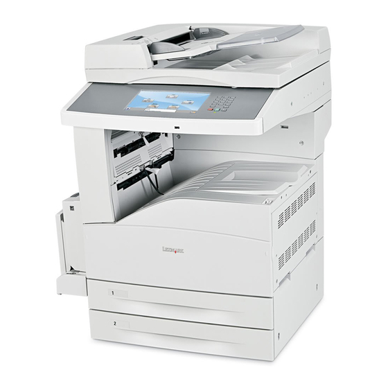
7500-432, -632, and -832 Previous Printer overview CAUTION: Do not set up this product or make any electrical or cabling connections, such as the power cord or options and features, during a lightning storm. Next Basic model Go Back The following illustration shows a printer with its base features. Operator panel Exit 2 (used in... -
Page 29: Configured Model
7500-432, -632, and -832 Configured model Previous The following illustration shows a fully configured printer. Items denoted with an asterisk (*) are options. Operator Next Exit 2 panel (Used in conjunction with duplex unit) Go Back Duplex unit Bridge unit* (Used in conjunction with finisher) Multipurpose... -
Page 30: Printer Theory
7500-432, -632, and -832 Previous Printer theory Driving force transmission path Media transport motor Next The rotating force of the transport motor is transmitted through the gear and the pulley (25 tooth) to components that need mechanical driving force as shown in the following diagram. Go Back Media transport motor Pulley25T... - Page 31 7500-432, -632, and -832 PC cartridge motor Previous The rotating force of the PC cartridge motor is transmitted through the gears to components that need a mechanical driving force as shown in the following diagram. PC cartridge motor Next Magnetic Roll Drum Go Back Transfer roll...
-
Page 32: Media Transport
7500-432, -632, and -832 Media transport Previous Media transport path Media is supplied from the MPF, tray 1 or tray 2, and is transported to the printer along the media transport path shown below. Next Tray 2 Tray 1 Go Back Pick roll Pick roll MPF pick roll... - Page 33 7500-432, -632, and -832 Media transport path layout Previous The following is a cross section of the laser printer, showing main components directly associated with the media path and transport. Main components associated with transport of media Next Exit 2 media exit roll ASM Exit 2 media exit pinch rolls Go Back Exit 2...
-
Page 34: Functions Of Main Components
7500-432, -632, and -832 Functions of main components Previous • Media tray assembly • Media feed unit assembly • • Xerographics Next • Fuser • Drive • Electrical components and rolls Go Back Media tray assembly It is necessary to adjust the front media tray guide assembly, rear media tray guide and media tray end guide of the media tray assembly to match the media size. -
Page 35: Media Tray Assembly
7500-432, -632, and -832 Media tray assembly Previous Media end guide Rear media tray guide Next Go Back Bottom plate Front media tray guide assembly Detection of media size The media size set for the media tray assembly is transmitted to the switch (media size) by moving these guides. The media size is detected by the on/off information of these switches. - Page 36 7500-432, -632, and -832 Sensor (media level) Previous This sensor detects by the actuator position whether media in the media tray assembly is lifted. When the flag of the actuator unblocks the sensing area of the sensor (media level), the sensor detects that the media has been lifted.
-
Page 37: Multi-Purpose Feeder (Mpf)
7500-432, -632, and -832 Multi-purpose feeder (MPF) Previous The MPF is a mechanical unit suppling media to the printer. The driving force from the transport motor of the dual drive motor assembly is transmitted to the MPF feed roll to feed media. MPF pick roll Next The MPF pick roll feeds media set on the MPF and into the feeder. -
Page 38: Detecting Media Size
7500-432, -632, and -832 Detecting media size Previous The size of media on the MPF is transmitted by moving the MPF side guide, and is determined by the printer engine card assembly. Media sizes that can be automatically detected are as follows: Next Media size Width (mm) -
Page 39: Registration
7500-432, -632, and -832 Registration Previous Sensor (registration) The sensor (registration) must be installed before the registration roll assembly can detect whether media exists in the registration path. Next Registration clutch Go Back The registration clutch transmits the drive force of the main motor to the registration roll assembly. Transport roll assembly The transport roll assembly feeds paper from the tray 2, TTM, and optional tray to the PC cartridge and fuser. -
Page 40: Printhead Assembly
7500-432, -632, and -832 charges on the rear surface of the media. Thus, the toner image is transferred from the drum surface to the Previous media surface. PC cartridge Transfer roll Next assembly Go Back Printhead assembly The printhead scans the drum surface with a laser beam. It consists of four components: laser diode (LD) card assembly, printhead motor, polygon mirror, and start of scan card assembly. - Page 41 7500-432, -632, and -832 Conceptual diagram of an image created by scanning Previous Next Go Back SOS card ASM LD card ASM Polygon mirror Printhead motor 1-17 General information...
-
Page 42: Fuser
7500-432, -632, and -832 Fuser Previous Heat roll The heat roll is a hollow metal tube with a coated surface. This tube is heated by the inner heater lamp. The heat is applied to the media passing between the heat roll and pressure roll, fusing the toner on the media. Next Pressure roll Go Back... -
Page 43: Exit
7500-432, -632, and -832 Fuser exit sensor Previous The fuser exit sensor detects the arrival of media at the detection point in the exit area of the fuser, and also detects the ejection of media from this point. Center thermistor Next Pressure roll thermistor Rear thermistor... - Page 44 7500-432, -632, and -832 Media diverter gate Previous The media diverter gate switches the media transport path. When the media diverter gate is lifted, media is fed to the standard bin exit 1. When it is lowered, media is fed to the standard bin exit 2. Media diverter gate Next Go Back...
-
Page 45: Drive
7500-432, -632, and -832 Drive Previous Media transport motor The media transport motor is a DC brushless motor that drives the exit 1 media exit shaft assembly, fuser assembly, registration roll assembly. Next PC cartridge motor Go Back The PC cartridge motor is a DC brushless motor that drives the PC cartridge, mag roll and transfer roll assembly. -
Page 46: Electrical Components And Controller
7500-432, -632, and -832 Electrical components and controller Previous Switch (main power) Turning on/off the switch, power supplies/cuts off the main power of the printer. Next Finisher AC output Supplies power to the finisher from the main LVPS (low voltage power supply) card assembly. Go Back Switch (printer front door interlock) and switch (printer left door interlock) The switch is a safety switch to cut off a 24 VDC power supply from the LVPS card assembly to the high volt... - Page 47 7500-432, -632, and -832 Registration roll assembly Previous Switch (PC cartridge interlock) Switch Next (main power) Switch (printer left door Go Back interlock) Switch (printer front door interlock) Fuser cooling fan AC drive card assembly Switch (printer left lower door interlock) LVPS Rear...
-
Page 48: Control
7500-432, -632, and -832 Previous Control Media size control Media tray assembly feeding Next The following table gives the states (on/off) of the switches on the switch (media size), corresponding to the media sizes of the media tray assembly. Go Back Note: The switches on the switch (media size) are denoted by “S/W2”, “S/W4”, “S/W3”, “S/W5”, and “S/W1”... -
Page 49: Printhead Control
7500-432, -632, and -832 Printhead control Previous Rotation of printhead motor The on/off control of the printhead motor is performed according to the mode of operation as shown below. Next Operation mode PRINTHEAD motor on/off Standby mode Always off Go Back Print mode Turns on upon receiving the signal from the controller, and turns off after a preset time has passed from the... -
Page 50: Xerographic Process During A Print Cycle
7500-432, -632, and -832 Xerographic Process During a Print Cycle Previous Next Go Back 1-26 MFP Service Manual... - Page 51 7500-432, -632, and -832 Charge Previous The Charge Roll places a uniform negative electrostatic charge on the surface of the drum. The drum surface is made of a photoconductive material that holds an electrical charge as long as the drum remains in darkness. Light striking the drum discharges the surface charge.
- Page 52 7500-432, -632, and -832 The charge roll is a conductive roll that is positioned slightly above the surface of the drum. The HVPS supplies Previous the charge roll with two voltages; a negative DC charge voltage and an AC discharge voltage that is used for electrically cleaning the drum.
- Page 53 7500-432, -632, and -832 The Printhead also helps to clean and prepare the drum by scanning the surface of the drum at the beginning of Previous each individual printer cycle. This action discharges a residual DC charge that may still remain on the Drum from the last print cycle.
- Page 54 7500-432, -632, and -832 The toner adhering to the Magnet Roll is always in contact with the drum surface. When a less negative point on Previous the drum (a discharged area) comes in contact with the more negative charged toner on the Magnet Roll, toner transfers from the Magnet Roll to that point on the drum.
- Page 55 7500-432, -632, and -832 Transfer Previous As the paper travels between the Transfer Roll and the drum surface, the Transfer Roll applies a positive charge to the back of the printing paper. This positive charge transfers the negative charged toner image from the drum surface to the top surface of the paper.
- Page 56 7500-432, -632, and -832 Cleaning Previous The Cleaning Blade removes any toner that remains on the drum after the transfer process. The toner that the Cleaning Blade removes is collected inside the sealed PC Cartridge and reused. Used Toner Next Cleaning Blade Go Back Charge roll...
-
Page 57: Safety System Diagram
7500-432, -632, and -832 Previous Safety system diagram Fuser cooling fan Switch Switch Switch Printhead (PC Cartridge (Printer front (Printer left Next Printhead interlock) door interlock) door interlock) Dual drive motor ASM motor PC cartridge Transport motor motor Go Back Printer engine card ASM Printhead motor Fuser... -
Page 58: Document Scanning
7500-432, -632, and -832 Previous Document scanning The document scanning section of this machine consists of a scanner that reads a single-sheet document placed on the platen glass and a document feeder that can transport a multiple-sheet document and flip the sheets for two-sided scanning. -
Page 59: Document Scanning At Adf
7500-432, -632, and -832 The full rate carriage and half rate carriage travel to read the document. Previous The exposure lamp is installed on the full rate carriage. As the full rate carriage travels, the document on the platen glass is scanned and exposed with the exposure lamp. In conjunction with the full rate carriage, the half rate carriage travels half of the stroke of the full rate carriage. - Page 60 7500-432, -632, and -832 Upon completion of document feed, the pick roll returns to the normal (raised) position. Previous Pre-feed In the pre-feed step, a document sheet is fed from the Feed roll to the ADF transport roll assembly. To correct the skew, side1 of the document sheet is thrust against the ADF transport roll assembly rotating in the reverse Next direction and side2 is thrust against the ADF transport roll assembly at rest.
- Page 61 7500-432, -632, and -832 Previous ADF transport roll assembly Next Go Back ADF registration roll assembly Scan control Scanning of the image illuminated with the exposure lamp of the full rate carriage is controlled by changing the feed speed according to the copy magnification. The document sheet stopping at the scan feed reference position is then fed to the scan position when the scan signal is sent from the main unit of the machine after the predetermined time lapse following the paper detection at sensor (ADF registration).
- Page 62 7500-432, -632, and -832 Previous ADF exit roll assembly Next Go Back Document Inverter gate Simplex document For two simplex document sheets, feed is performed in the following sequence: The first document sheet is fed to the ADF transport roll assembly. (see Pre-feed) The document is fed to the ADF registration roll assembly, and then fed to the scan feed reference position.
- Page 63 7500-432, -632, and -832 Previous Sensor (ADF pre-registration) 2nd documant Next Go Back 1st document Duplex document The ADF scans the image on Side 1 (side facing up when set on the tray), inverts the document sheet, scans the image on Side 2 (side facing down when set on the tray), and then ejects the document sheet while inverting Therefore, the duplex document sheet is ejected with Side 2 up as with the simplex document sheet.
- Page 64 7500-432, -632, and -832 When the sensor (ADF pre-registration) detects the lead edge of document sheet (Side 1), the inverter Previous solenoid assembly is turned on to release the nipped ADF exit roll assembly and exit pinch roll and the ADF registration motor decelerates and stops.
-
Page 65: Image Data Flow
7500-432, -632, and -832 Previous Image data flow The image date from the document set on the scanner unit assembly or ADF goes through the following components before it is printed at the Engine section. Next Document Go Back Lens CCD image sensor Scanner controller card assembly Scanner... -
Page 66: Drive Torque Transfer Scheme
7500-432, -632, and -832 Previous Drive torque transfer scheme ADF feed motor assembly The rotational force of the ADF feed motor assembly is transferred to each document feeding roll as shown Next below. ADF feed motor assembly Go Back ADF drive belt Feed drive rear pulley 14/32/37 Transport roll drive belt Feed/pick drive gear 20T... -
Page 67: Adf Registration Motor
7500-432, -632, and -832 ADF registration motor Previous The rotational force of the ADF registration motor is transferred to each document feeding roll as shown below. Gear layout Next ADF registration motor Go Back Registration roll drive belt Registration drive gear/pulley 21/54T Registration drive belt Exit/feed-out drive... - Page 68 7500-432, -632, and -832 Previous Feed/pick drive gear 20T Feed drive gear/pulley14/32/37T ADF feed motor assembly Transport roll drive Feed roll drive gear 26T Next gear pulley 20/50T Pick roll idler gear 36T Exit roll drive pulley 20T Go Back ADF registration motor Pick roll drive gear 34T Pick roll...
-
Page 69: Names And Functions Of Components
7500-432, -632, and -832 Previous Names and functions of components The sections below describe the functions of main components of the scanner. Scanner unit assembly Next Sensor (platen length APS 1) Go Back Sensor (platen length APS 2) The document length in the slow scanning direction is detected by a combination of the two reflector sensors. Switch (platen interlock) A switch that detects whether the ADF is open and determines the timing of platen document size detection. -
Page 70: Adf
7500-432, -632, and -832 Scanner cooling fan Previous A fan that prevents overheating of the scanner controller card assembly and exposure lamp. Scanner drive motor assembly Next Exposure lamp PS card assembly Go Back (under the carriage) Sensor (platen length APS1) Scanner cooling fan Sensor (platen ADF angle... - Page 71 7500-432, -632, and -832 Sensor (pick roll position HP) Previous A sensor that detects the home position of the pick roll. ADF Document Set LED Next An LED that illuminates when a document is set on the ADF Document Tray. Switch (ADF left cover interlock) Go Back A switch that detects whether the ADF left cover assembly is open.
- Page 72 7500-432, -632, and -832 Sensor (ADF pre-registration) Previous The ADF sensor (ADF pre-registration) is installed immediately upstream from the ADF transport roll assembly to detect that the preceding document sheet has left the ADF transport roll assembly, triggering the pre-feed of the next document sheet.
- Page 73 7500-432, -632, and -832 Previous Sensor (ADF pre-registration) ADF feed motor assembly Sensor (sheet through) Next ADF registration motor Go Back Sensor (ADF registration) Inverter solenoid assembly Sensor (ADF inverter) Sensor (ADF APS 3) Sensor (ADF APS 2) Sensor (ADF APS 1) 1-49 General information...
-
Page 74: Control
7500-432, -632, and -832 Previous Control Document size detection at scanner unit assembly The width (fast-scan-directional size) of the document sheet on the Platen Grass is detected with the CCD Next image sensor, and the length (slow-scanning-directional size) is detected with the sensor (platen length APS 1) and the sensor (platen length APS 2). - Page 75 7500-432, -632, and -832 Shown below are the combinations of document size, detection range in the fast scanning direction, and Previous sensors. Width (Fast scanning Length (Slow scanning direction) Area direction: mm) Next Document Size Fast Detection Sensor (platen Sensor (platen scanning Range length APS 1)
-
Page 76: Adf Document Size Detection
7500-432, -632, and -832 Previous Width (Fast scanning Length (Slow scanning direction) Area direction: mm) Document Size Fast Detection Sensor (platen Sensor (platen scanning Range length APS 1) length APS 2) Width Next A4 LEF 297.2 289—307 A3 SEF 297.2 Go Back O: Detectable by default. - Page 77 7500-432, -632, and -832 The standard document sizes to be identified by the same given detection information are defined on an Previous area-by-area basis. Each area is to be set in the system data. Document tray media size actuator Next Go Back Sensor (document tray width 1) Sensor (document tray width 2)
- Page 78 7500-432, -632, and -832 The table below shows the combinations of document sizes and sensors. Previous Width (Fast scanning direction) Length (Slow scanning direction) Area Sensor (document tray width *) Sensor (document tray length *) Document Size Next 5.5 X 8.5 SEF A5 SEF Go Back B5 SEF...
-
Page 79: Document Scanning Steps
7500-432, -632, and -832 Document scanning steps Previous The CCD image sensor is used to read image data from the document. To stabilize the read image data, the CCD image sensor output is adjusted and the read image data is compensated. The CCD image sensor output is adjusted with the gain/offset voltage of the amplifier in the analog circuit. -
Page 80: Tandem Tray Theory
7500-432, -632, and -832 Previous Tandem tray theory Next Go Back 1-56 MFP Service Manual... -
Page 81: Driving Force Transmission Path
7500-432, -632, and -832 Driving force transmission path Previous 2 tray / tandem tray drive motor assembly The rotating force of the 2 tray / tandem tray motor is transmitted through the gears to components that require mechanical driving force as shown below. Next 2TM/TTM drive motor Go Back... -
Page 82: Media Transport
7500-432, -632, and -832 Media transport Previous Media transport path Media is supplied from tray 3 or tray 4, and is transported to the printer along the media transport path shown below. Next Tray 4 Tray 3 Go Back Pick roll Pick roll Separation roll Separation roll... - Page 83 7500-432, -632, and -832 Media transport path Previous The following is a cross section of the printer and the tandem tray module, showing the main components directly associated with the media path and transport. Exit 2 media exit roll ASM Next Exit 2 media exit pinch rolls Exit 2...
-
Page 84: Media Tray Assembly
7500-432, -632, and -832 Media tray assembly Previous Media feed unit assembly It is necessary to adjust the front and rear side guides in the media tray assembly to match the media size. Next Front media guide / rear media guide The front media guide can be adjusted to different media sizes by moving it to the front or rear. - Page 85 7500-432, -632, and -832 Tray 4 media tray assembly Previous Rear lift cables Rear media guide Next Front media guide Go Back Bottom plate F/R lift cable F/L lift cable Media feed unit assembly Since the tray 3 and tray 4 are functionally equivalent in terms of the switch (TTM media size), sensor (media out), sensor (media level) and sensor (pre-feed), only the components of one tray are described here.
- Page 86 7500-432, -632, and -832 Sensor (media level) Previous This sensor detects by the actuator position whether media in the media tray assembly is lifted. When the flag of the actuator leaves the sensor (media level) sensing area, the sensor detects that the media has been lifted. Sensor (pre-feed) Next This sensor detects a media jam in the media tray assembly by the media position and sensor on/off time.
-
Page 87: Main Components
7500-432, -632, and -832 Main components Previous Switch (2TM/TTM left door interlock) The left door interlock switch detects open/close of the left door assembly. Next Sensor (tray 3 feed-out) The sensor (tray 3 feed-out) detects media fed from the tray 3 or tray 4. Go Back Sensor (tray 4 feed-out) The sensor (tray 4 feed-out) detects media fed from the tray 4. - Page 88 7500-432, -632, and -832 Switch (tandem tray media size) Previous The following table gives on/off states of the switches on the switch (TTM media size), corresponding to the media sizes of the media tray assembly. Note: The switches (TTM media size) are denoted by “S/W1” and “S/W3” respectively from the left side. Next Analog switch Media Size...
-
Page 89: Duplex
7500-432, -632, and -832 Previous Duplex Next Go Back Duplex drive motor The rotating force of the drive motor is transmitted through the gears to components that need mechanical driving force as shown below. Duplex drive motor Duplex drive gear 33/74T Duplex drive gear 33/74T Duplex drive gear 28T Duplex drive gear 28T... -
Page 90: Media Transport
7500-432, -632, and -832 Media transport Previous Media transport path With the duplex installed, media is supplied from the MPF, tray 1 or tray 2, and is transported to the printer along the media transport path shown below. Next Tray 1 Tray 2 Go Back Pick roll... - Page 91 7500-432, -632, and -832 Layout of media transport path Previous The main components associated with the media path and transport with the duplex installed. Exit 2 media exit roll ASM Exit 2 media exit pinch rolls Next Exit 2 Exit 2 media transport roll ASM Go Back Exit 1 media exit roll ASM Duplex...
- Page 92 7500-432, -632, and -832 Duplex media transport roll assembly Previous The two duplex media transport roll assemblies and the duplex media center transport roll assembly re-feeds the media printed on the front side through the duplex to print on the rear side. Duplex controller card assembly Next The duplex controller card assembly that contains a CPU controls media feed in the duplex upon receiving a...
-
Page 93: Exit 2
7500-432, -632, and -832 Previous Exit 2 Next Go Back Exit 2 drive motor The rotating force of the exit 2 drive motor is transmitted through the gears to components that need mechanical driving force as shown below. Exit 2 drive motor Exit 2 drive gear 19T Exit 2 drive gear 19T Exit 2 drive gear 19/44T... -
Page 94: Media Transport
7500-432, -632, and -832 Media transport Previous Media transport path With the exit 2 installed, media is supplied from the MPF, tray 1, or tray 2 and is transported to the printer along the media transport path shown below. Next Tray 2 Tray 1 Go Back... - Page 95 7500-432, -632, and -832 Layout of media transport path Previous The following figure illustrates the main components directly associated with the media path and transport with the exit 2 installed. Exit 2 media exit roll ASM Next Exit 2 media exit pinch rolls Exit 2 Go Back Exit 2 media transport roll ASM...
- Page 96 7500-432, -632, and -832 Exit interface card assembly (located in the printer) Previous The exit interface card assembly contains a CPU and controls media feed in the exit 2 upon receiving a command from the printer engine card assembly and sensor/switch information. Exit 2 left door assembly Next The left door assembly detects open/close of the exit 2.
-
Page 97: Tools Required For Service
7500-432, -632, and -832 Exit 2 transport roll assembly and media exit roll assembly Previous The exit 2 transport roll assembly and exit 2 media exit roll assembly are rollers used to eject media to the exit 2 standard bin or to feed media to the duplex. Sensor (exit 2 media shift HP) Next Sensor (standard bin full exit 2) -
Page 98: Acronyms
7500-432, -632, and -832 Previous Acronyms 2 Tray Module Alternating Current Automatic Document Feeder Next Automatic Paper Size ASIC Application Specific Integrated Circuit Customer Replaceable Unit Go Back Customer Setup Counterclockwise Clockwise Direct Current DIMM Dual Inline Memory Module DRAM Dynamic Random Access Memory Enhanced Data Out Electrophotographic Process... - Page 99 7500-432, -632, and -832 Tandem Tray Module Previous TVOC Total Volatile Organic Compound Used Parts Return Volts V ac Volts alternating current V dc Volts direct current Next Go Back 1-75 General information...
- Page 100 7500-432, -632, and -832 Previous Next Go Back 1-76 MFP Service Manual...
-
Page 101: Diagnostic Information
7500-432, -632, and -832 2. Diagnostic information Previous Start Next CAUTION—SHOCK HAZARD: Remove the power cord from the electrical outlet and then from the printer before connecting or Go Back disconnecting any cable, assembly, or electronic board. This is a precaution for personal safety and to prevent damage to the printer. -
Page 102: Confirm The Installation Status
The following is an example of the events that occur during the POR sequence: Turn the machine on. The Lexmark splash screen appears with a progress bar in the center until the code is loaded. The scanner exposure lamp flashes several times. -
Page 103: Understanding The Printer Operator Panel
7500-432, -632, and -832 Previous Understanding the printer operator panel Next PQRS WXYZ Go Back Item Function Display View scanning, copying, faxing, and printing options as well as status and error messages. Keypad Enter numbers, letters, or symbols on the display. PQRS WXYZ Diagnostic information... - Page 104 7500-432, -632, and -832 Previous Pound or number character Press • For a shortcut identifier. • Within phone numbers. For a Fax number with a #, enter it twice— • From the home screen, the Fax Destination List menu item, E-mail Destination List menu item, or Profile List menu item to access Next shortcuts.
-
Page 105: Understanding The Home Screen
7500-432, -632, and -832 Previous Understanding the home screen After the MFP is turned on and a short warm-up period occurs, the display shows the following basic screen which is referred to as the Home screen. Use the Home screen buttons to initiate an action such as copying, faxing, or scanning; to open the menu screen;... -
Page 106: Other Buttons May Appear On The Home Screen
7500-432, -632, and -832 • Shows the current MFP status such as Ready or Busy. Previous Status message bar • Shows MFP conditions such as Toner Low. • Shows intervention messages to give instructions on what the user should do so the MFP can continue processing, such as Close door or Insert print cartridge. - Page 107 7500-432, -632, and -832 Previous Unlock Device This button appears on the screen when the printer is locked. The printer operator panel buttons and shortcuts cannot be used while it appears. Touching this button opens a PIN entry screen. Entering the correct PIN unlocks the printer operator panel (touch screen and hard buttons).
-
Page 108: Using The Touch-Screen Buttons
7500-432, -632, and -832 Previous Using the touch-screen buttons Note: Depending on your options and administrative setup, your screens and buttons may vary from those shown. Next Sample touch screen Go Back Button Function Home Returns to the home screen Scroll down Opens a drop-down list Left scroll decrease... -
Page 109: Other Touch-Screen Buttons
7500-432, -632, and -832 Previous Button Function Right arrow Scrolls right Next Submit Saves a value as the new user default setting Go Back Submit Back Navigates back to the previous screen Other touch-screen buttons Button Function Down arrow Moves down to the next screen Up arrow Moves up to the next screen Unselected radio button... -
Page 110: Features
7500-432, -632, and -832 Previous Button Function Continue Touch this button when more changes need to be made for a job or after clearing a paper jam. Next Go Back Cancel • Cancels an action or a selection • Cancels out of a screen and returns to the previous screen Select Selects a menu or menu item Features... -
Page 111: Error Code Messages
7500-432, -632, and -832 Previous Error code messages Error code or Error contents Description/Action message Next 200.00 Sensor (registration) off The sensor (registration) is not turned off within the jam (too long) specified time after the registration clutch is turned Paper jam Go Back Check area A... - Page 112 7500-432, -632, and -832 Previous Error code or Error contents Description/Action message 230.00 Sensor (duplex wait) on jam The sensor (duplex wait) is not turned on within the specified time after the exit2 motor is turned on. Paper jam Go to “230.00 Sensor (duplex wait) on jam”...
- Page 113 7500-432, -632, and -832 Previous Error code or Error contents Description/Action message 243.00 Sensor (pre-feed) on jam The sensor (pre-feed) is not turned on within the (tray 3 media feed) specified time after the tray 3 feed lift motor is Paper jam turned on.
- Page 114 7500-432, -632, and -832 Previous Error code or Error contents Description/Action message 244.02 Sensor (tray 2 feed-out) on The sensor (tray 2 feed-out) is not turned on within jam (tray 4 media feed) the specified time after the sensor (tray 4 feed-out) Paper jam is turned on.
- Page 115 7500-432, -632, and -832 Previous Error code or Error contents Description/Action message 280.00 Sensor (bridge unit media Sensor (bridge unit media entrance) is not turned on entrance) on jam within the specified time after the sensor (fuser exit) Paper jam in the printer is turned on.
- Page 116 7500-432, -632, and -832 Previous Error code or Error contents Description/Action message 283.01 Sensor (buffer path) on jam B Sensor (buffer path) is not turned on within the specified time after the sensor (finisher media Paper jam entrance is turned on. Next Check area At this time, the sensor (diverter gate) is turned on.
- Page 117 7500-432, -632, and -832 Previous Error code or Error contents Description/Action message 284.05 Sensor (lower media exit) Paper remains on the sensor (lower media exit). static jam Paper jam Refer to the Options Service Manual. Next Check area H 285.00 Finisher set eject jam Finisher sensor (compiler media in) is not turned on within the specified time after the media eject motor...
- Page 118 7500-432, -632, and -832 Previous Error code or Error contents Description/Action message 287.06 Sensor (upper media exit) Paper remains on the sensor (upper media exit). static jam B Paper jam At this time, the sensor (bridge unit media exit) is off state but the finisher sensor (finisher media Next Check areas...
- Page 119 7500-432, -632, and -832 Previous Error code or Error contents Description/Action message 290.00 Switch (sheet through) static The system detected that the sensor (sheet through) is on. Scanner jam Go to “290.00 Switch (sheet through) static jam” Next Remove all on page 2-83.
- Page 120 7500-432, -632, and -832 Previous Error code or Error contents Description/Action message 290.14 Sensor (ADF inverter) on jam After the sensor (ADF registration) turned on during (Inverting) the Invert operation, the sensor (ADF inverter) did Scanner jam not turn on within the specified time. Next Remove all Go to...
- Page 121 7500-432, -632, and -832 Previous Error code or Error contents Description/Action message 291.03 Sensor (ADF inverter) off jam After the sensor (ADF registration) turned off during the Read operation of the last document, the sensor Scanner jam (ADF inverter) did not turn off within the specified Next time.
- Page 122 7500-432, -632, and -832 Previous Error code or Error contents Description/Action message 295.04 Too Long Size Jam The system detected a document with the following length in the Slow Scan Direction: Scanner jam • Simplex mode: 672.4mm or longer Next Remove all •...
- Page 123 7500-432, -632, and -832 Previous Error code or Error contents Description/Action message 841.00 Image pipeline ASIC failure The image pipeline for processing the data that comes from the scanner, prior to being printed, has Service image failed. pipeline Next Go to “841.00 Image pipeline ASIC failure”...
- Page 124 7500-432, -632, and -832 Previous Error code or Error contents Description/Action message 843.01 Scanner carriage over run The scanner carriage has over run. failure Service Go to “843.01 Scanner carriage over run failure” scanner on page 2-131. Next failure 843.10 ADF RAM test failure The ADF controller card assembly RAM has failed in the read/write operation.
- Page 125 7500-432, -632, and -832 Previous Error code or Error contents Description/Action message 843.26 Scanner controller card An internal processing failure occurred in the assembly failure 2 scanner controller card assembly. Service scanner Go to “843.26 Scanner controller card assembly Next failure failure 2”...
- Page 126 7500-432, -632, and -832 Previous Error code or Error contents Description/Action message 849.00 Hard drive/configuration ID The device does not have a hard drive installed, mismatch even though its configuration ID indicates that a Service hard hard drive should be present. drive Next Go to...
- Page 127 7500-432, -632, and -832 Previous Error code or Error contents Description/Action message 911.00 Transport motor failure The transport motor does not rotate at the specified speed. Service motor error Go to “911.00 Transport motor failure” on Next page 2-151. 912.00 PC cartridge unit motor The PC cartridge motor does not rotate at the failure...
- Page 128 7500-432, -632, and -832 Previous Error code or Error contents Description/Action message 920.00 Fuser unit assembly on time During the warm-up period, the control thermistor failure does not detect the ready temperature even when Service fuser the specified time is passed after the main lamp is error Next turned on.
- Page 129 7500-432, -632, and -832 Previous Error code or Error contents Description/Action message 929.00 Sensor (ATC) failure The sensor (ATC) failed. Service PC Go to “929.00 Sensor (ATC) failure” on cartridge page 2-162. Next 930.00 Laser power failure Light intensity of the LD2 is less than the specified value.
- Page 130 7500-432, -632, and -832 Previous Error code or Error contents Description/Action message 945.00 Media tray 5 lift up/no tray The sensor (HCF media level) is not turned on with failure the specified time after the HCF feed lift motor is Service tray 5 turned on.
- Page 131 7500-432, -632, and -832 Previous Error code or Error contents Description/Action message 980.03 Exit interface card assembly, A communication error occurred between the printer communication failure engine card assembly and the exit interface card Service assembly. standard bin Next comm. Go to “980.03 Exit interface card assembly communication failure”...
- Page 132 7500-432, -632, and -832 Previous Error code or Error contents Description/Action message 984.00 Sensor (punch unit HP) on The sensor (punch unit HP) is not turned on even failure when the specified time passed after the punch unit Service motor is turned on. finisher error Next Refer to the Options Service Manual.
- Page 133 7500-432, -632, and -832 Previous Error code or Error contents Description/Action message 989.00 Stapler unit failure The off/on status of the sensor (stapler unit motor HP) is not detected within the specified time after Service the stapler unit motor (forward operation). finisher error Next Or the sensor (stapler unit motor HP) is not turned...
- Page 134 7500-432, -632, and -832 Previous Error code or Error contents Description/Action message Check tray 1 Media size mismatch in The media width is incorrect. or tray 2 width. Go to “Media size mismatch in width” on orientation or page 2-177. Next guides Check tray 2...
- Page 135 7500-432, -632, and -832 Previous Error code or Error contents Description/Action message Load tray 1 or No media in the selected Media is not loaded in the tray. tray 2 with media tray. Go to “No media in the select media tray” on <media>...
-
Page 136: Service Checks
7500-432, -632, and -832 Previous Service checks 200.00 Sensor (registration) off jam (too long) Next Step Check Go Back Check the media position. Remove the Go to step 2. media. Open the printer left door assembly, and visually check it. Does the media touch the sensor (registration)? Check the roll. -
Page 137: Sensor (Registration) Static On Jam
7500-432, -632, and -832 200.01 Sensor (registration) static on jam Previous Step Check Check the media position. Remove the Go to step 2. Next media. Open the printer left door assembly, and visually check it. Does the media touch the sensor (registration)? Go Back Check the sensor (registration) for proper operation. -
Page 138: Sensor (Fuser Exit) On Jam
7500-432, -632, and -832 201.00 Sensor (fuser exit) on jam Previous Step Check Check the media position. Remove the Go to step 2. Next media. Does the media touch the sensor (fuser exit)? Open the printer left door assembly, and visually check it. Go Back Check the fuser exit actuator. -
Page 139: Sensor (Fuser Exit) Off Jam
7500-432, -632, and -832 Previous Step Check Check the registration clutch connection. Replace the Replace the registration clutch. connection. Is the registration clutch properly connected? Go to Next “Registration clutch assembly removal” on page 4-80. Go Back Perform a print test. Replace the Problem solved. -
Page 140: Sensor (Fuser Exit) Off (Too Short) Jam
7500-432, -632, and -832 202.01 Sensor (fuser exit) off (too short) jam Previous Step Check Check the media position. Remove the Go to step 2. Next media. Open the printer left door assembly, and visually check it. Does the media touch the sensor (fuser exit)? Go Back Check the fuser unit assembly for a media jam. -
Page 141: Sensor (Fuser Exit) Static Jam
7500-432, -632, and -832 202.02 Sensor (fuser exit) static jam Previous Step Check Check the media position. Remove the Go to step 2. Next media. Open the printer left door assembly, and visually check it. Does the media touch the sensor (fuser exit)? Go Back Open the printer left door assembly, and check it. - Page 142 7500-432, -632, and -832 Previous Step Check Check the drive power transmission. Go to step 5. Replace damaged components. Does the exit 1 media exit roll assembly and the other gears rotate smoothly? Go to “Exit 1 media Next shift assembly removal”...
-
Page 143: Sensor (Exit 2) Off Jam
7500-432, -632, and -832 Previous Step Check Check the media diverter solenoid for proper operation. Go to step 13. Go to step 12. 1. Enter the Diagnostics Menu. Next 2. Touch MOTOR TESTS. 3. Touch Printer Motor Test. 4. Touch Diverter solenoid. Go Back Open the printer left door assembly. - Page 144 7500-432, -632, and -832 Previous Step Check Check the drive power transmission. Go to step 6. Replace damaged parts. Do the exit 2 media exit roll assembly and the other gears rotate smoothly? Go to “Exit 2 unit Next assembly removal” on page 4-322.
-
Page 145: Sensor (Exit 2) On Jam In Standard Bin Or Finisher
7500-432, -632, and -832 203.02 Sensor (exit 2) on jam in standard bin or finisher Previous Step Check Check the position of the media diverter solenoid. Go to step 2. Go to step 3. Next Is the media diverter gate facing toward exit 1? Check the media diverter gate for an obstruction. -
Page 146: Sensor (Exit 2) Static Jam
7500-432, -632, and -832 Previous Step Check Perform a print test. Replace the printer Problem solved. engine card Does the error still occur? assembly. Next Go to “Printer engine card assembly removal” on page 4-119. Go Back 203.03 Sensor (exit 2) static jam Step Check Check the media position. -
Page 147: Sensor (Duplex Wait) On Jam
7500-432, -632, and -832 230.00 Sensor (duplex wait) on jam Previous Step Check Check the media position. Remove the media. Go to step 2. Next Does the media remain in the exit 2? Open the exit 2 left door assembly, and visually check it. Go Back Check the roll. -
Page 148: Sensor (Duplex Wait) On Jam
7500-432, -632, and -832 Previous Step Check Check the sensor (duplex wait) for proper connection. Replace the sensor Replace the (duplex wait). connection. Is the above sensor connected properly? Go to “Duplex Next sensor (duplex wait) removal” on page 4-314. Go Back Perform a print test. - Page 149 7500-432, -632, and -832 Previous Step Check Check the drive power transmission. Go to step 6. Replace damaged components. Do the exit 2 media exit roll assembly and the other gears rotate smoothly? Go to “Exit 2 unit Next assembly removal” on page 4-322.
-
Page 150: Sensor (Duplex Wait) Static Jam
7500-432, -632, and -832 230.01 Sensor (duplex wait) static jam Previous Step Check Check the paper position. Remove the paper. Go to step 2. Next Open the duplex left door assembly, and visually check Go Back Does the paper touch the duplex wait actuator? Check the sensor (duplex wait) for proper operation. - Page 151 7500-432, -632, and -832 Previous Step Check Check the roll. Go to step 4. Clean or replace the duplex media Open the duplex left door assembly. transport roll Next assembly. Is the duplex media transport roll assembly free of excess wear and contamination? Go to “Duplex media transport...
-
Page 152: Sensor (Registration) On Jam (Duplex Paper Feed)
7500-432, -632, and -832 Previous Step Check Perform a 2 sided print test. Replace the printer Problem solved. engine card Does the error still occur? assembly. Next Go to “Printer engine card assembly removal” on page 4-119. Go Back 231.01 Sensor (registration) on jam (duplex paper feed) Step Check Check the paper position. - Page 153 7500-432, -632, and -832 Previous Step Check Check the drive power transmission. Go to step 8. Replace damaged components. Open the duplex left door assembly. Go to “Duplex Next Do the duplex media center transport roll assembly and media center the other gears rotate smoothly? transport roll removal”...
-
Page 154: Sensor (Pre-Feed) On Jam (Tray 1 Feed)
7500-432, -632, and -832 241.00 Sensor (pre-feed) on jam (tray 1 feed) Previous Step Check Check the media condition. Replace the Go to step 2. Next damaged media Is the media in the tray crumpled or damaged? with new. Check the media size setup. Go to step 3. -
Page 155: Sensor (Registration) On Jam (Tray 1 Feed)
7500-432, -632, and -832 Previous Step Check Check the media feed lift motor for proper operation of Re-install the Go to step 10. tray 1. media feed lift motor for tray 2 as Replace the media feed lift motor for tray 1 with one from Next it previously was, tray 2. -
Page 156: Sensor (Pre-Feed) On Jam (Tray 2 Feed)
7500-432, -632, and -832 Previous Step Check Check the sensor (registration) for proper operation. Go to step 7. Go to step 6. 1. Enter the Diagnostics Menu. Next 2. Touch BASE SENSOR TEST. 3. Touch Media Path. 4. Touch Registration. Go Back Open the printer left door assembly. - Page 157 7500-432, -632, and -832 Previous Step Check Check the rolls for tray 2. Go to step 4. Clean or replace the feed roll, Remove tray 2 and check it. separation roll, Next and pick roll. Are the feed roll, separation roll, and pick roll free of excess wear and contamination? Go to “Feed roll...
-
Page 158: Sensor (Tray 2 Feed-Out) On Jam (Tray 2 Feed)
7500-432, -632, and -832 Previous Step Check Check the media feed lift motor in tray 2 for proper Install the media Go to step 10. operation. feed lift motor for tray 1 as it Replace the media feed lift motor for tray 2 with the one Next previously was, from tray 1. - Page 159 7500-432, -632, and -832 Previous Step Check Check the sensor (tray 2 feed-out) for proper operation. Go to step 7. Go to step 6. 1. Enter the Diagnostics Menu. Next 2. Touch INPUT TRAY TESTS. 3. Touch Sensor test. 4. Touch Tray 2. 5.
-
Page 160: Sensor (Registration) On Jam (Tray 2 Feed)
7500-432, -632, and -832 Previous Step Check Perform a print test. Replace the Problem solved. printer engine card Does the error continue? assembly. Next Go to “Printer engine card assembly removal” on Go Back page 4-119. 242.02 Sensor (registration) on jam (tray 2 feed) Step Check Check the media condition. - Page 161 7500-432, -632, and -832 Previous Step Check Check the sensor (registration) connection. Replace the Replace the sensor connection. Is the sensor (registration) properly connected? (registration). Next Go to “Sensor (registration) removal” on page 4-81. Go Back Check the sensor (tray 2 feed-out) for proper operation. Go to step 10.
-
Page 162: Sensor (Tray 2 Feed-Out) Static Jam
7500-432, -632, and -832 242.03 Sensor (tray 2 feed-out) static jam Previous Step Check Check the media position. Remove the Go to step 2. Next media. Does the media touch the sensor (tray 2 feed-out)? Open the printer left lower door assembly, and visually Go Back check it. - Page 163 7500-432, -632, and -832 Previous Step Check Check the media position. Remove the media. Go to step 5. Open the 2TM/TTM left door assembly, and visually check it. Next Does the media touch the sensor (pre-feed) of the tray 3 media feed unit assembly? Go Back Check the tray 3 sensor (pre-feed) for proper operation.
-
Page 164: Sensor (Tray 3 Feed-Out) On Jam (Tray 3 Media Feed)
7500-432, -632, and -832 Previous Step Check Perform a print test. Replace the 2TM/ Problem solved. TTM controller card Does the error still occur? assembly. Next Go to “2000-sheet dual input (TTM)— 2TM/TTM controller card assembly Go Back removal” on page 4-281. - Page 165 7500-432, -632, and -832 Previous Step Check Check the sensor (tray 3 feed-out) for proper operation. Go to step 7. Go to step 6. 1. Enter the Diagnostics Menu. Next 2. Touch INPUT TRAY TESTS. 3. Touch Sensor Test. 4. Touch Tray 3. 5.
-
Page 166: Sensor (Tray 2 Feed-Out) On Jam (Tray 3 Media Feed)
7500-432, -632, and -832 Previous Step Check Perform a print test. Replace the printer Problem solved. engine card Does the error still occur? assembly. Next Go to “Printer engine card assembly removal” on page 4-119. Go Back 243.02 Sensor (tray 2 feed-out) on jam (tray 3 media feed) Step Check Check the media condition. -
Page 167: Sensor (Registration) On Jam (Tray 3 Media Feed)
7500-432, -632, and -832 Previous Step Check Check the sensor (tray 2 feed-out) for proper Replace the sensor Replace the connection. (tray 2 feed-out). connection. Is the above sensor connected properly? Go to “Sensor Next (tray 2 feed-out) removal” on page 4-83. - Page 168 7500-432, -632, and -832 Previous Step Check Check the media size setup. Go to step 3. Replace the media, or change the media Does the media size in use match the size set for tray size setup. Next Check the tray 3 rolls. Go to step 4.
-
Page 169: Sensor (Tray 3 Feed-Out) Static Jam
7500-432, -632, and -832 Previous Step Check Check the sensor (tray 3 feed-out) for proper Replace the sensor Replace the connection. (tray 3 feed-out). connection. Is the above sensor connected properly? Go to “2000-sheet Next dual input (TTM)— sensor (tray 3 feed- out) removal”... -
Page 170: Sensor (Tray 4 Feed-Out) On Jam (Tray 4 Media Feed)
7500-432, -632, and -832 Previous Step Check Check the sensor (tray 3 feed-out) for proper Replace the sensor Replace the connection. (tray 3 feed-out). connection. Is the above sensor connected properly? Go to “2000-sheet Next dual input (TTM)— sensor (tray 3 feed- out) removal”... - Page 171 7500-432, -632, and -832 Previous Step Check Check the tray 4 sensor (pre-feed) for proper operation. Go to step 7. Go to step 6. 1. Enter the Diagnostics Menu. Next 2. Touch INPUT TRAY TESTS. 3. Touch Sensor Test. 4. Touch Tray 4. 5.
- Page 172 7500-432, -632, and -832 Previous Step Check Remove the tray 4 media transport assembly from the Straighten the metal Go to step 11. TTM. tab with needle nose pliers, or replace the Go to “2000-sheet dual input (TTM)—tray 4 media Next tray 4 media transport assembly removal”...
-
Page 173: Sensor (Tray 3 Feed-Out) On Jam (Tray 4 Media Feed)
7500-432, -632, and -832 244.01 Sensor (tray 3 feed-out) on jam (tray 4 media feed) Previous Step Check Check the media condition. Replace the media. Go to step 2. Next Is the media in the tray, crumpled or damaged? Check the media size setup. Go to step 3. - Page 174 7500-432, -632, and -832 Previous Step Check Check the sensor (tray 3 feed-out) for proper operation. Go to step 10. Go to step 9. 1. Enter the Diagnostics Menu. Next 2. Touch INPUT TRAY TESTS. 3. Touch Sensor Test. 4. Touch Tray 3. 5.
-
Page 175: Sensor (Tray 2 Feed-Out) On Jam (Tray 4 Media Feed)
7500-432, -632, and -832 Previous Step Check Perform a print test. Replace the 2TM/ Problem solved. TTM controller card Does the error still occur? assembly. Next Go to “2000-sheet dual input (TTM)— 2TM/TTM controller card assembly Go Back removal” on page 4-281. - Page 176 7500-432, -632, and -832 Previous Step Check Check the sensor (tray 2 feed-out) for proper operation. Go to step 8. Go to step 7. 1. Enter the Diagnostics Menu. Next 2. Touch INPUT TRAY TESTS. 3. Touch Sensor Test. 4. Touch Tray 2. 5.
-
Page 177: Sensor (Registration) On Jam (Tray 4 Media Feed)
7500-432, -632, and -832 Previous Step Check Perform a print test. Replace the printer Problem solved. engine card Does the error still occur? assembly. Next Go to “Printer engine card assembly removal” on page 4-119. Go Back 244.03 Sensor (registration) on jam (tray 4 media feed) Step Check Check the media condition. -
Page 178: Sensor (Pre-Feed) On Jam (Tray 4 Media Feed)
7500-432, -632, and -832 Previous Step Check Check the sensor (registration) for proper connection. Replace the sensor Replace the (registration). connection. Is the above sensor connected properly? Go to “Sensor Next (registration) removal” on page 4-81. Go Back Check the sensor (tray 4 feed-out) for proper operation. Go to step 10. - Page 179 7500-432, -632, and -832 Previous Step Check Check the media size setup. Go to step 3. Replace the media, or change the media Does the media size in use match the size set for size setup. tray 4? Next Check the tray 4 rolls. Go to step 4.
-
Page 180: Sensor (Tray 4 Feed-Out) Static Jam
7500-432, -632, and -832 Previous Step Check Check the tray 4 media feed lift motor for proper Reinstall the media Replace the 2TM/ operation. feed lift motor for TTM controller card tray 3 as it assembly. Replace the media feed lift motor for tray 4 with that for Next previously was, and tray 3. -
Page 181: Sensor (Registration) On Jam (Mpf Pick)
7500-432, -632, and -832 Previous Step Check Check the sensor (tray 4 feed-out) for proper Replace the sensor Replace the connection. (tray 4 feed-out). connection. Is the above sensor connected properly? Go to “2000-sheet Next dual input (TTM)— sensor (tray 4 feed- out) removal”... - Page 182 7500-432, -632, and -832 Previous Step Check Check the roll. Go to step 7. Clean or replace the MPF feed roll Remove the MPF pick unit assembly. assembly. Next Is the MPF feed roll assembly free of excess wear and Go to “MPF feed contamination?
-
Page 183: Switch (Sheet Through) Static Jam
7500-432, -632, and -832 290.00 Switch (sheet through) static jam Previous Step Check Check the sensor (sheet through). Go to step 2. Remove any Next media or media Is the feed media path free of media or media fragments? fragments. Check the sensor (sheet through) for operation. - Page 184 7500-432, -632, and -832 Previous Step Check Check the ADF rolls for wear. Go to step 3. Clean or replace the ADF feed/pick Is the ADF feed/pick roll assembly or the ADF separation roll roll assembly or assembly free of excess wear? Next the ADF separation roll...
- Page 185 7500-432, -632, and -832 Previous Step Check Check the feed drive motor connection. Replace the ADF Replace the feed drive motor connection. Is the above motor connected properly? assembly. Next Go to “ADF feed drive motor assembly removal” on Go Back page 4-180.
-
Page 186: Sensor (Adf Pre-Registration) On Jam Adf Simplex Side 1
7500-432, -632, and -832 290.02 Sensor (ADF pre-registration) on jam ADF simplex side 1 Previous Step Check Check the original document condition. Go to step 2. Remove damaged Next original document, Is the original document free of paper clips and staples as and replace with a well as damage such as creases, tears, holes, or excessive new undamaged... - Page 187 7500-432, -632, and -832 Previous Step Check Check the sensor (ADF pre registration) for operation. Go to step 7. Go to step 6. Perform the sensor (ADF pre registration) test. Next Open the ADF left cover assembly. 1. Enter the Diagnostics Menu. 2.
-
Page 188: Sensor (Adf Pre-Registration) Off Jam
7500-432, -632, and -832 290.03 Sensor (ADF pre-registration) off jam Previous Step Check Check the original document condition. Go to step 2. Remove damaged Next original document, Is the original document free of paper clips and staples as and replace with a well as damage such as creases, tears, holes, or excessive new undamaged wear? - Page 189 7500-432, -632, and -832 Previous Step Check Check the sensor (ADF pre registration) for operation. Go to step 8. Go to step 7. Perform the sensor (ADF pre registration) test. Next Open the ADF left cover assembly. 1. Enter the Diagnostics Menu. 2.
-
Page 190: Sensor (Adf Pre-Registration) Static Jam
7500-432, -632, and -832 Previous Step Check Check the ADF registration motor for connection. Replace the ADF Replace the registration connection. Is the above motor connected properly? motor. Next Go to “ADF registration motor removal” on page 4-209. Go Back Place an undamaged document in the ADF, and perform a Replace the ADF Go to step 13. -
Page 191: Sensor (Adf Registration) On Jam Adf Simplex Side 1
7500-432, -632, and -832 Previous Step Check Place an undamaged document in the ADF, and perform a Replace the Go to step 5. ADF test. ADF controller card assembly. Does the error remain? Next Go to “ADF controller card assembly removal”... - Page 192 7500-432, -632, and -832 Previous Step Check Check the sensor (ADF registration) for operation. Go to step 6. Go to step 5. Perform the sensor (ADF registration) test. Next Open the ADF left cover assembly. 1. Enter the Diagnostics Menu. 2.
-
Page 193: Sensor (Adf Registration) On Jam Side 2
7500-432, -632, and -832 290.12 Sensor (ADF registration) on jam side 2 Previous Step Check Check the original document condition. Go to step 2. Remove damaged Next original document, Is the original document free of paper clips and staples as and replace with a well as damage such as creases, tears, holes, or excessive new undamaged... - Page 194 7500-432, -632, and -832 Previous Step Check Check the feed drive motor for correct operation. Go to step 9. Go to step 8. Perform the feed drive motor test. Next Open the ADF left cover assembly. Remove the ADF rear cover. Go to “ADF rear cover removal”...
-
Page 195: Sensor (Adf Registration) Off Jam
7500-432, -632, and -832 290.13 Sensor (ADF registration) off jam Previous Step Check Check the original document condition. Go to step 2. Remove damaged Next original document, Is the original document free of paper clips and staples as and replace with a well as damage such as creases, tears, holes, or excessive new undamaged wear? - Page 196 7500-432, -632, and -832 Previous Step Check Check the media path for contaminates. Go to step 5. Remove all contaminates from Is the media path free of excess media dust and foreign the media path. objects such as paper clips and staples? Next Check the sensor (ADF registration) for operation.
-
Page 197: Sensor (Adf Inverter) On Jam (Inverting)
7500-432, -632, and -832 Previous Step Check Place an undamaged document in the ADF, and perform a Replace the RIP Problem solved. ADF test. card assembly. Does the error remain? Go to “RIP card Next assembly removal” on page 4-130. Go Back 290.14 Sensor (ADF inverter) on jam (Inverting) Step... - Page 198 7500-432, -632, and -832 Previous Step Check Check the sensor (ADF inverter) for connection. Replace the Replace the sensor (ADF connection. Is the above sensor connected properly? inverter). Next Go to “Sensor (ADF inverter)” on page 4-197. Go Back Check the registration motor (forward or reverse) test. Go to step 8.
-
Page 199: Sensor (Adf Registration) Off Jam (Inverting)
7500-432, -632, and -832 Previous Step Check Place an undamaged document in the ADF, and perform a Replace the RIP Problem solved. ADF test. card assembly. Does the error remain? Go to “RIP card Next assembly removal” on page 4-130. Go Back 290.15 Sensor (ADF registration) off jam (inverting) Step... - Page 200 7500-432, -632, and -832 Previous Step Check Check the sensor (ADF registration) for operation. Go to step 6. Go to step 5. Perform the sensor (ADF registration) test. Next Open the ADF left cover assembly. 1. Enter the Diagnostics Menu. 2.
- Page 201 7500-432, -632, and -832 Previous Step Check Check the feed drive motor for connection. Replace the Replace the ADF feed drive connection. Is the above sensor connected properly? motor Next assembly. Go to “ADF feed drive Go Back motor assembly removal”...
-
Page 202: Sensor (Adf Width Aps 1) Static Jam
7500-432, -632, and -832 Previous Step Check Place an undamaged document in the ADF, and perform Replace the Go to step 15. a ADF test. ADF controller card assembly. Next Does the error remain? Go to “ADF controller card assembly Go Back removal”... -
Page 203: Sensor (Adf Width Aps 2) Static Jam
7500-432, -632, and -832 Previous Step Check Place an undamaged document in the ADF, and perform a Replace the RIP Problem solved. ADF test. card assembly. Does the error remain? Go to “RIP card Next assembly removal” on page 4-130. Go Back 290.22 Sensor (ADF width APS 2) static jam Step... -
Page 204: Sensor (Adf Width Aps 3) Static Jam
7500-432, -632, and -832 290.23 Sensor (ADF width APS 3) static jam Previous Step Check Check the sensor (ADF width APS 3). Go to step 2. Remove any Next media or media Is the feed media path free of media or media fragments? fragments. -
Page 205: Sensor (Adf Inverter) Off Jam (Inverting)
7500-432, -632, and -832 Previous Step Check Check the sensor (ADF registration) for operation. Go to step 4. Go to step 3. Perform the sensor (ADF registration) test. Next Open the ADF left cover assembly. 1. Enter the Diagnostics Menu. 2. - Page 206 7500-432, -632, and -832 Previous Step Check Check the ADF rolls for wear. Go to step 3. Clean or replace the ADF feed/pick Is the ADF feed/pick roll assembly or the ADF separation roll assembly or roll guide assembly free of excess wear? Next the ADF separation roll...
-
Page 207: Sensor (Adf Inverter) On Jam 2
7500-432, -632, and -832 Previous Step Check Check the ADF registration motor for connection. Replace the ADF Replace the registration motor. connection. Is the above motor connected properly? Go to “ADF Next registration motor removal” on page 4-209. Go Back Place an undamaged document in the ADF, and perform a Replace the ADF Go to step 9. - Page 208 7500-432, -632, and -832 Previous Step Check Check the sensor (ADF inverter) for operation. Go to step 6. Go to step 5. Perform the sensor (ADF inverter) test. Next Open the ADF left cover assembly. Remove the ADF separation roll guide assembly. Go to “ADF separation roll guide assembly”...
-
Page 209: Sensor (Adf Inverter) Off Jam
7500-432, -632, and -832 Previous Step Check Place an undamaged document in the ADF, and perform a Replace the ADF Go to step 10. ADF test. controller card assembly. Does the error remain? Next Go to “ADF controller card assembly removal”... - Page 210 7500-432, -632, and -832 Previous Step Check Check the sensor (ADF inverter) for operation. Go to step 6. Go to step 5. Perform the sensor (ADF inverter) test. Next Open the ADF left cover assembly. Remove the ADF separation roll guide assembly. Go to “ADF separation roll guide assembly”...
- Page 211 7500-432, -632, and -832 Previous Step Check Check the registration motor (forward or reverse) test. Go to step 11. Go to step 10. Perform the registration motor test. Next Open the ADF left cover assembly. Remove the ADF rear cover. Go to “ADF rear cover removal”...
-
Page 212: Sensor (Adf Inverter) Static Jam
7500-432, -632, and -832 294.00 Sensor (ADF inverter) static jam Previous Step Check Check the sensor (ADF inverter). Go to step 2. Remove any Next media or media Is the feed media path free of media or media fragments? fragments. Check the sensor (ADF inverter) for operation. -
Page 213: Sensor (Adf Pre-Registration) On Jam Side 2
7500-432, -632, and -832 294.01 Sensor (ADF pre-registration) on jam side 2 Previous Step Check Check the original document condition. Go to step 2. Remove damaged Next original document Is the original document free of paper clips and staples as and replace with a well as damage such as creases, tears, holes, or excessive new undamaged... - Page 214 7500-432, -632, and -832 Previous Step Check Check the registration motor (forward or reverse) test. Go to step 9. Go to step 8. Perform the registration motor test. Next Open the ADF left cover assembly. Remove the ADF rear cover. Go to “ADF rear cover removal”...
-
Page 215: Sensor (Adf Pre-Registration) Off Jam On Inverting
7500-432, -632, and -832 294.02 Sensor (ADF pre-registration) off jam on inverting Previous Step Check Check the original document condition. Go to step 2. Remove damaged Next original document Is the original document free of paper clips and staples as and replace with a well as damage such as creases, tears, holes, or excessive new undamaged... - Page 216 7500-432, -632, and -832 Previous Step Check Check the sensor (ADF pre registration) for operation. Go to step 8. Go to step 7. Perform the sensor (ADF pre registration) test. Next Open the ADF left cover assembly. 1. Enter the Diagnostics Menu. 2.
-
Page 217: Size Mismatch Jam (Mix-Size)
7500-432, -632, and -832 Previous Step Check Check the inverter solenoid assembly for connection. Replace the Replace the inverter solenoid connection. Is the above motor connected properly? assembly. Next Go to “Inverter solenoid assembly removal” on Go Back page 4-181. Check the registration motor (forward or reverse) test. - Page 218 7500-432, -632, and -832 Previous Step Check Check the sensor (ADF width APS 1) for operation. Go to step 2. Go to step 3. Perform the sensor (ADF width APS 1) test. Next Open the ADF left cover assembly. 1. Enter the Diagnostics Menu. Go Back 2.
-
Page 219: Size Mismatch Jam (No Mix-Size)
7500-432, -632, and -832 Previous Step Check Check the sensor (ADF width APS 3) for connection. Replace the Replace the sensor (ADF connection. Is the above sensor connected properly? width APS 3). Next Go to “Sensor (ADF width APS 3)” on page 4-194. -
Page 220: Invalid Combine Size Jam
7500-432, -632, and -832 295.02 Invalid combine size jam Previous Step Check Check the document size. Go to step 2. Insert the proper Next size document into Is the correct size document being inserted into the ADF? the ADF. Check the document tray media guide position. Go to step 3. -
Page 221: Too Short Size Jam
7500-432, -632, and -832 Previous Step Check Check the sensor (ADF width APS 3) for operation. Go to step 10. Go to step 9. Perform the sensor (ADF width APS 3) test. Next Open the ADF left cover assembly. 1. Enter the Diagnostics Menu. Go Back 2. - Page 222 7500-432, -632, and -832 Previous Step Check Check the sensor (sheet through) for operation. Go to step 4. Go to step 3. Perform the sensor (sheet through) test. Next Open the ADF left cover assembly. Remove the ADF rear cover. Go to “ADF rear cover removal”...
-
Page 223: Too Long Size Jam
7500-432, -632, and -832 295.04 Too long size jam Previous Step Check Check the document size. Go to step 2. Insert the proper Next size document Is the correct size document being inserted into the ADF? into the ADF. Check the sensor (sheet through) for operation. Go to step 4. -
Page 224: Scanner Cable Missing Or Unplugged
7500-432, -632, and -832 Previous Step Check Place an undamaged document in the ADF, and perform a Replace the RIP Problem solved. ADF test. card assembly. Does the error remain? Go to “RIP card Next assembly removal” on page 4-130. Go Back 298.01 Scanner cable missing or unplugged Step... -
Page 225: Scanner Communication Failure
7500-432, -632, and -832 Previous Step Check Turn the printer off for 60 seconds. Replace the RIP Problem solved. card assembly. Does the error occur when the power is turned off/on again? Go to “RIP card Next assembly removal” on page 4-130. -
Page 226: Scanner Communication Failure
7500-432, -632, and -832 Previous Step Check Perform a POR. Replace the Problem solved. scanner Does the error remain when the power is turned off/on? controller card Next assembly. Go to “Scanner controller card assembly Go Back removal” on page 4-151. -
Page 227: Scanner Communication Failure
7500-432, -632, and -832 842.03 Scanner communication failure Previous Step Check Check the scanner interface cable assembly connection Go to step 2. Replace the Next between the RIP card assembly and the scanner unit connection. assembly. Is the scanner interface cable assembly connected properly? Go Back Check all connections of the scanner controller card assembly. -
Page 228: Scanner Unit Assembly - Adf Communication Failure
7500-432, -632, and -832 Previous Step Check Perform a POR. Replace the RIP Problem solved. card assembly. Does the error remain when the power is turned off/on again? Go to “RIP card Next assembly removal” on page 4-130. Go Back 842.10 Scanner unit assembly - ADF communication failure Step Check... -
Page 229: Scanner Unit Assembly Communication Failure
7500-432, -632, and -832 Previous Step Check Perform a POR. Replace the Problem solved. ADF controller Does the error remain when the power is turned off/on? card assembly. Next Go to “ADF controller card assembly removal” on Go Back page 4-175. -
Page 230: Sensor (Scanner Hp) Failure
7500-432, -632, and -832 843.00 Sensor (scanner HP) failure Previous Step Check Check the scanner carriage rails. Clean and Go to step 2. Next lubricate the Is there any foreign substance on the scanner rails? scanner carriage rails. Go Back Check the sensor (scanner HP) for operation. -
Page 231: Scanner Carriage Over Run Failure
7500-432, -632, and -832 843.01 Scanner carriage over run failure Previous Step Check Check the connections of the scanner controller card Go to step 2. Connect each Next assembly. connector of the scanner Are the connectors of the scanner controller card assembly controller card connected properly? assembly... -
Page 232: Adf Pick Roll Position Lift Up Failure
7500-432, -632, and -832 Previous Step Check Perform a POR. Replace the Problem solved. ADF controller Does the error remain when the power is turned off/on? card assembly. Next Go to “ADF controller card assembly removal” on Go Back page 4-175. -
Page 233: Scanner Unit Assembly Connection Failure
7500-432, -632, and -832 Previous Step Check Check the pick roll position motor assembly for connection. Replace the Replace the pick roll position connection. Is the above motor connected properly? motor Next assembly. Go to “Pick roll position motor assembly Go Back removal”... -
Page 234: Scanner Unit Assembly Eeprom Sub System Failure
7500-432, -632, and -832 Previous Step Check Perform a POR. Replace the Problem solved. ADF controller Does the error remain when the power is turned off/on? card assembly. Next Go to “ADF controller card assembly Go Back removal” on page 4-175. -
Page 235: Image Processing Failure
7500-432, -632, and -832 Previous Step Check Perform a POR. Replace the Problem solved. scanner Does the error remain when the power is turned off/on? controller card Next assembly. Go to “Scanner controller card assembly Go Back removal” on page 4-151. -
Page 236: Scanner Controller Card Assembly Failure 2
7500-432, -632, and -832 Previous Step Check Perform a POR. Replace the Problem solved. scanner PS card Does the error remain when the power is turned off/on again? assembly. Next Go to “Scanner PS card assembly removal” on Go Back page 4-162. -
Page 237: White Reference/Exposure Lamp Illumination Failure
7500-432, -632, and -832 Previous Step Check Check the exposure lamp for connection. Replace the Replace the exposure lamp. connection. Is the above component connected properly? Go to “Exposure Next lamp removal” on page 4-166. Check the exposure lamp PS card assembly. Replace the Replace the Go Back... - Page 238 7500-432, -632, and -832 Previous Step Check Remove the large platen glass. Check the bottom of the large Clean the bottom Go to step 4. platen glass in the vicinity the white reference strip for of the large contamination. platen glass in Next the vicinity of the Is the vicinity of white reference strip contaminated?
-
Page 239: Ccd Failure
7500-432, -632, and -832 845.00 CCD failure Previous Step Check Check the CCD/lens assembly connection. Go to step 2. Replace the Next connection. Is the CCD/lens assembly connected properly? Check all the connections on the scanner controller card Replace the Replace the Go Back assembly. -
Page 240: Ccd Initialization (Lamp Off) Failure
7500-432, -632, and -832 Previous Step Check Perform a POR. Replace the Problem solved. scanner Does the error remain when the power is turned off/on? controller card Next assembly. Go to “Scanner controller card assembly Go Back removal” on page 4-151. -
Page 241: Sensor (Adf Width Aps X) Failure
7500-432, -632, and -832 Previous Step Check Perform a POR. Replace the Problem solved. scanner Does the error remain when the power is turned off/on? controller card Next assembly. Go to “Scanner controller card assembly Go Back removal” on page 4-151. - Page 242 7500-432, -632, and -832 Previous Step Check Check the sensor (ADF width APS 1) for connection. Replace the Replace the sensor (ADF connection. Is the above sensor connected properly? width APS 1). Next Go to “Sensor (ADF width APS 1)” on page 4-192.
-
Page 243: Scanner Unit Assembly Software Logic Failure
7500-432, -632, and -832 846.12 Scanner unit assembly software logic failure Previous Step Check Check the software version for the scanner controller card Go to step 2. Upgrade the Next assembly. software of the scanner controller Is the version of the software of the scanner controller card card assembly. -
Page 244: Hard Drive Failure
7500-432, -632, and -832 Previous Step Check Place an undamaged document in the ADF, and perform a Replace the Go to step 6. ADF test. scanner controller card Does the error remain? Next assembly. Go to “Scanner controller card assembly Go Back removal”... -
Page 245: System Software Error
Note: Before troubleshooting, determine the operating system used when the error occured. If possible Go Back determine whether a PostScript or PCL file was sent to the device when the error occured. Ask the customer which Lexmark Solutions applications are installed on the device. Step Action and questions POR the device. - Page 246 Reinstall the memory, and send a print job to the Go to step 15. Go to step 16. device. Does the 900.xx error reoccur? Install a Lexmark recommended memory option. Send Go to step 31. Problem a print job to the device. resolved.
-
Page 247: Ram Read/Write Check Failure
7500-432, -632, and -832 Previous Step Action and questions Replace the faulty ISP option. Restart the device. Go to step 31. Go to step 26. Does the 900.xx error reoccur? Are there any more ISP options to install? Go to step 27 Problem Next resolved. -
Page 248: Nvm Data Failure
7500-432, -632, and -832 904.00 NVM data failure Previous Step Check Perform a POR. Go to step 2. Perform several Next print tests. Does the error occur when the power is turned off/on? If the problem remains, go to Go Back step 2. -
Page 249: Cpu Power To Access Nvm Failure
7500-432, -632, and -832 906.00 CPU power to access NVM failure Previous Step Check Perform a POR. Go to step 2. Perform several Next print tests. Does the error occur when the power is turned off/on? If the problem remains, go to Go Back step 2. -
Page 250: Ppm Data Failure
7500-432, -632, and -832 908.00 PPM data failure Previous Step Check Perform a POR. Go to step 2. Perform several Next print tests. Does the error occur when the power is turned off/on? If the problem remains, go to Go Back step 2. -
Page 251: Transport Motor Failure
7500-432, -632, and -832 Previous Step Check Check the dual drive motor assembly rotation operation. Go to step 4 Go to step 3. Open the rear motor cover and check it. Next 1. Enter the Diagnostics Menu. 2. Touch MOTOR TESTS. 3. -
Page 252: Pc Cartridge Unit Motor Failure
7500-432, -632, and -832 Previous Step Check Perform a print test. Replace the Problem solved. printer engine card Does the error continue? assembly. Next Go to “Printer engine card assembly removal” on Go Back page 4-119. 912.00 PC cartridge unit motor failure Step Check Check the PC cartridge for proper installation. -
Page 253: Printhead Assembly Failure
7500-432, -632, and -832 913.00 Printhead assembly failure Previous Step Check Check the printhead assembly for proper installation. Go to step 2. Install the Next printhead Is the printhead assembly installed properly? assembly properly. Go Back Check the printhead assembly connection. Replace the Replace the printhead. -
Page 254: Fuser Cooling Fan Failure
7500-432, -632, and -832 Previous Step Check Check the toner add motor assembly connection. Replace the toner Replace the add motor. connection. Is the toner add motor assembly properly connected? “Toner cartridge Next guide assembly removal” on page 4-95 Go Back Perform a print test. -
Page 255: Lvps Cooling Fan Failure
7500-432, -632, and -832 Previous Step Check Check the PC cartridge cooling fan. Remove the object Go to step 3. blocking the Is there an object blocking the PC cartridge cooling fan rotation. rotation? Next Check the PC cartridge cooling fan for operation. Go to step 5. -
Page 256: Sensor (Exit 1 Media Shift Hp) Failure
7500-432, -632, and -832 918.00 Sensor (exit 1 media shift HP) failure Previous Step Check Check the sensor (exit 1 media shift HP) for operation. Go to step 3. Go to step 2. Next 1. Enter the Diagnostics Menu. 2. Touch BASE SENSOR TEST. 3. -
Page 257: Sensor (Exit 2 Media Shift Hp) Failure
7500-432, -632, and -832 919.00 Sensor (exit 2 media shift HP) failure Previous Step Check Check the sensor (exit 2 media shift HP) for proper Go to step 3. Go to step 2. Next operation. 1. Enter the Diagnostics Menu. 2. -
Page 258: Exit 2 Unit Assembly Connection Failure
7500-432, -632, and -832 919.01 Exit 2 unit assembly connection failure Previous Step Check Check the exit 2 unit assembly for proper installation. Go to step 2. Reinstall the exit 2 Next unit assembly, and Is the exit 2 unit assembly installed properly? POR. -
Page 259: Over Heat Temperature Failure
7500-432, -632, and -832 Previous Step Check Perform a print test. Replace the Problem solved. printer engine card Does the error continue? assembly. Next Go to “Printer engine card assembly removal” on Go Back page 4-119. 921.00 Over heat temperature failure Step Check Check the fuser unit assembly for proper installation. -
Page 260: Rear Thermistor Failure
7500-432, -632, and -832 923.00 Rear thermistor failure Previous Step Check Check the fuser unit assembly for proper installation. Go to step 2. Install the fuser Next unit assembly Open the printer left door assembly, and check it. properly. Is the fuser unit assembly installed properly? Go Back Check the fuser unit assembly connection. -
Page 261: Pc Cartridge Rfid Data Write Failure
7500-432, -632, and -832 Previous Step Check Check the fuser unit assembly for proper installation. Go to step 4. Install the fuser unit assembly Open the printer left door assembly, and check it. properly. Next Is the fuser unit assembly installed properly? Check the fuser unit assembly connection. -
Page 262: Sensor (Atc) Failure
7500-432, -632, and -832 Previous Step Check Check the sensor (RFID PC cartridge) installation. Go to step 3. Install the sensor (RFID PC Is the sensor (RFID PC cartridge) properly installed? cartridge) Next correctly. Check the sensor (RFID PC cartridge) connection. Replace the Replace the sensor (RFID PC... -
Page 263: Toner Cartridge Rfid Data Write Failure
7500-432, -632, and -832 932.00 Toner cartridge RFID data write failure Previous Step Check Check the toner cartridge installation. Go to step 2. Install the toner Next cartridge properly. Is the toner cartridge properly installed? Check the sensor (RFID toner cartridge) installation. Go to step 3. -
Page 264: Media Tray 1 Lift Up / No Media Tray Failure
7500-432, -632, and -832 Previous Step Check Turn the printer off for 60 seconds. Go to step 3. Problem solved. Does the error occur when the power is turned off/on again? Next Check the RIP card assembly connection. Replace the RIP Replace the card assembly. -
Page 265: Media Tray 2 Lift Up / No Media Tray Failure
7500-432, -632, and -832 Previous Step Check Check the tray 1 sensor (media level) for operation. Go to step 8. Go to step 7. 1. Enter the Diagnostics Menu. Next 2. Touch INPUT TRAY TESTS. 3. Touch Sensor test. 4. Touch Tray 1. 5. - Page 266 7500-432, -632, and -832 Previous Step Check Check the tray 2 media feed lift motor for proper operation. Go to step 8. Go to step 5. Warning: Only perform this test with the paper tray assembly removed from the machine, or abnormal grinding Next noises will occur.
-
Page 267: Tray 3 Lift Up / No Tray Failure
7500-432, -632, and -832 943.00 Tray 3 lift up / no tray failure Previous Step Check Check the media. Go to step 2. Load media Next properly. Pull out the tray 3, and visually check it. Is any media loaded in tray 3? Go Back Check the tray. -
Page 268: Tray 4 Lift Up / No Tray Failure
7500-432, -632, and -832 Previous Step Check Check the switch (TTM media size) for proper Replace the switch Replace the connection. (TTM media size). connection. Is the above switch connected properly? Go to “2000-sheet Next dual input (TTM)— switch (TTM media size) removal”... - Page 269 7500-432, -632, and -832 Previous Step Check Check the 2TM/TTM controller card assembly and the Go to step 6. Replace the printer engine card assembly for proper connection. connection. Are connectors P541 and P413 on the above cards Next connected properly? Check the tray 4 sensor (media level) for proper Go to step 8.
-
Page 270: Rip Card Assembly Nvram Failure
7500-432, -632, and -832 951.XX RIP card assembly NVRAM failure Previous Step Check Perform a POR. Go to step 2. Perform several Next print tests. Does the error occur when the power is turned off/on? If the problem remains, go to Go Back step 2. -
Page 271: Rip Card Assembly Processor Failure
7500-432, -632, and -832 Previous Step Check Turn the printer off for 60 seconds. Replace the RIP Problem solved. card assembly. Does the error occur when the power is turned off/on again? Go to “RIP card Next assembly removal” on page 4-130. -
Page 272: Rip Card Assembly Fpga Failure
7500-432, -632, and -832 Previous Step Check Turn the printer off for 60 seconds. Go to step 3. Problem solved. Does the error occur when the power is turned off/on again? Next Check the RIP card assembly cooling fan and heatsink Replace the RIP Reattach the RIP attachment. -
Page 273: Exit Interface Card Assembly Communication Failure
7500-432, -632, and -832 980.03 Exit interface card assembly communication failure Previous Step Check Check the exit interface card assembly for proper Go to step 2. Replace the Next connection. connection. Check the connection between the exit interface card Go to step 3. Replace the assembly P430 and the LVPS assembly P526. -
Page 274: Engine Flicker Communication Failure
7500-432, -632, and -832 980.05 Engine flicker communication failure Previous Step Check Perform a POR. Go to step 2. Perform several Next print tests. Does the error occur when the power is turned off/on? If the problem remains, go to Go Back step 2. -
Page 275: 2Tm/Ttm Left Door Assembly Open
7500-432, -632, and -832 2TM/TTM left door assembly open Previous Step Check Check the 2TM/TTM left door assembly for opening and Go to step 2. Check the 2TM/TTM Next closing. left door assembly for deformation, and Does the 2TM/TTM left door assembly open or close reinstall it. -
Page 276: Duplex Left Door Assembly Open
7500-432, -632, and -832 Duplex left door assembly open Previous Step Check Check the duplex left door assembly for opening and Go to step 2. Check the duplex Next closing. left cover assembly for deformation and Does the duplex left door assembly open or close reinstall it. -
Page 277: Media Size Mismatch In Width
7500-432, -632, and -832 Previous Step Check Check the switch (exit 2 left door interlock) for proper Reconnect the Go to step 3. operation. connector of the printer engine card 1. Enter the Diagnostics Menu. Next assembly. 2. Touch BASE SENSOR TEST. 3. -
Page 278: Media Size Mismatch In Width
7500-432, -632, and -832 Previous Step Check Check the switch (media size) connection for tray 1 and/or Replace the Replace the tray 2. required switch connection. (media size). Is the switch (media size) properly connected for tray 1 and/or Next tray 2? Go to “Toner... -
Page 279: No Media In The Select Media Tray
7500-432, -632, and -832 Previous Step Check Perform a print test. Replace the 2TM/ Problem solved. TTM controller card Does the error still occur? assembly. Next Go to “2000-sheet dual input (TTM)— 2TM/TTM controller card assembly Go Back removal” on page 4-281. - Page 280 7500-432, -632, and -832 Previous Step Check Perform a print test. Replace the Problem solved. printer engine card Does the error continue? assembly. Next Go to “Printer engine card assembly removal” on Go Back page 4-119. No media in the select media tray Step Check Check the media.
-
Page 281: Paper Is Installed (Short Edge) In The Media Paper Tray
7500-432, -632, and -832 Previous Step Check Perform a print test. Replace the printer Problem solved. engine card Does the error still occur? assembly. Next Go to “Printer engine card assembly removal” on page 4-119. Go Back Paper is installed (short edge) in the media paper tray Step Check Is the media installed (short edge) orientation in the media... -
Page 282: Pc Cartridge Rfid Failure
7500-432, -632, and -832 Previous Step Check Perform a print test. Replace the Problem solved. printer engine card Does the error continue? assembly. Next Go to “Printer engine card assembly removal” on Go Back page 4-119. PC cartridge RFID failure Step Check Check the PC cartridge installation. -
Page 283: Printer Front Door Open
7500-432, -632, and -832 Previous Step Check Check the PC cartridge sensor connection. Replace the PC Reinstall the PC cartridge sensor cartridge sensor Is the PC cartridge sensor connector installed and connector. connector and functioning properly? Next ensure it connects to the PC cartridge properly. -
Page 284: Printer Left Door Open
7500-432, -632, and -832 Previous Step Check Check the switch (printer front door interlock) connection. Replace the switch Replace the (printer front door connection. Is the switch (printer front door interlock) properly interlock). connected? Next Go to “Switch (printer front door interlock) removal”... -
Page 285: Printer Left Lower Door Open
7500-432, -632, and -832 Printer left lower door open Previous Step Check Is the printer left lower door assembly opening and closing Go to step 2. Check the printer Next properly? front door assembly for deformation and reinstall it. Go Back Check the switch (printer front door interlock) for operation. -
Page 286: Standard Bin 2 Full
7500-432, -632, and -832 Previous Step Check Check the sensor (standard bin full exit 1) for operation. Go to step 5. Go to step 3. 1. Enter the Diagnostics Menu. Next 2. Touch BASE SENSOR TEST. 3. Touch Exit level. 4. -
Page 287: Scanner Missing Failure
7500-432, -632, and -832 Previous Step Check Check the sensor (standard bin full exit 2) connection. Replace the Replace the sensor (standard connection. Is the sensor (standard bin full exit 2) properly connected? bin full exit 2). Go to step 4. Next Go to “Exit 2... -
Page 288: Switch (Adf Left Cover Interlock) Open
7500-432, -632, and -832 Switch (ADF left cover interlock) open Previous Step Check Check the actuator of the ADF left cover assembly. Go to step 2. Replace the ADF Next left cover Is the above actuator present and attached properly? assembly. - Page 289 7500-432, -632, and -832 Previous Step Check Check the toner cartridge guide assembly. Go to step 4. Replace toner cartridge guide Remove the toner cartridge guide assembly. assembly. Next Does the gear, located on the lower part of the toner cartridge guide assembly, rotate smoothly? Check the pipe, located on the lower part of the toner Go to step 5.
-
Page 290: Toner Cartridge Near Empty
7500-432, -632, and -832 Toner cartridge near empty Previous Step Check Does the toner cartridge contain toner? Go to step 2. Replace the toner Next cartridge. Check the toner cartridge for proper installation. Problem solved Go to step 3. Go Back Remove the toner cartridge and reinstall it. -
Page 291: Toner Cartridge Rfid Failure
7500-432, -632, and -832 Previous Step Check Check the sensor (RFID toner cartridge) connection. Replace the Replace the sensor (RFID connection. Is the sensor (RFID toner cartridge) properly connected? toner cartridge). Next Perform a print test. Replace the Problem solved. printer engine card Does the error continue? assembly. -
Page 292: Tray 1 Media Size Failure
7500-432, -632, and -832 Previous Step Check Check the toner cartridge guide assembly. Remove the top Replace the toner Go to step 4. cover assembly. Is the toner cartridge guide assembly cartridge. damaged? Go to “Toner Next cartridge guide assembly removal”... -
Page 293: Tray 2 Media Size Failure
7500-432, -632, and -832 Tray 2 media size failure Previous Step Check Check the media. Go to step 2. Load media Next properly. Is the media loaded, in media tray 2, properly? Pull out the media tray 2, and visually check it. Go Back Check the media. - Page 294 7500-432, -632, and -832 Previous Step Check Check the roll for tray 1. Go to step 6. Clean or replace the feed roll, Pull out the tray 1, and check it. separation roll, Next and pick roll. Is the feed roll, separation roll, and pick roll free of excess wear and contamination? Check the media position.
-
Page 295: Tray 2 Media Size Mismatch In Length
7500-432, -632, and -832 Previous Step Check Perform a print test. Replace the Problem solved. printer engine card Does the error continue? assembly. Next Go to “Printer engine card assembly removal” on Go Back page 4-119. Tray 2 media size mismatch in length Step Check Check the media. - Page 296 7500-432, -632, and -832 Previous Step Check Check the roll. Go to step 8. Clean or replace the transport roll Open the printer left door assembly, and check it. assembly. Next Is the transport roll assembly free of excess wear and Go to “Transfer contamination?
-
Page 297: Tray 3 Media Size Failure
7500-432, -632, and -832 Tray 3 media size failure Previous Step Check Check the media. Go to step 2. Load media Next properly. Pull out the tray 3, and visually check it. Is the media loaded in tray 3 properly? Go Back Check the media. -
Page 298: Tray 4 Media Size Failure
7500-432, -632, and -832 Tray 4 media size failure Previous Step Check Check the media. Go to step 2. Load media Next properly. Pull out the tray 4, and visually check it. Is the media loaded in tray 4 properly? Go Back Check the media. -
Page 299: Tray 3 Media Size Mismatch In Length
7500-432, -632, and -832 Tray 3 media size mismatch in length Previous Step Check Check the media. Go to step 2. Load media Next properly. Pull out the tray 3, and visually check it. Is the media loaded in tray 3 properly? Go Back Check the media. - Page 300 7500-432, -632, and -832 Previous Step Check Check the roll. Go to step 10. Clean or replace the registration roll Open the printer left door assembly, and visually check assembly. Next Go to “Registration Is the registration roll assembly for transport free of roll assembly excess wear and contamination? removal”...
-
Page 301: Tray 4 Media Size Mismatch In Length
7500-432, -632, and -832 Tray 4 media size mismatch in length Previous Step Check Check the media. Go to step 2. Load media Next properly. Pull out the tray 4, and visually check it. Is the media loaded in tray 4 properly? Go Back Check the media. - Page 302 7500-432, -632, and -832 Previous Step Check Check the roll. Go to step 9. Clean or replace the media transport roll Open the printer left door assembly, and visually check assembly. Next Go to “2000-sheet Is the media transport roll assembly for transport free of dual input (TTM)—...
-
Page 303: Image Quality Trouble
7500-432, -632, and -832 Previous Step Check Perform a print test. Replace the printer Problem solved. engine card Does the error still occur? assembly. Next Go to “Printer engine card assembly removal” on page 4-119. Go Back Image quality trouble Troubleshooting Note: First, get a printout as a base, and follow the symptom table to identify the possible failing FRU’s. -
Page 304: Image Quality
7500-432, -632, and -832 Image Quality Previous Faint print (Low contrast) Leading edge Next Go Back Trailing edge Before starting, check the media route for foreign objects, such as staples, clips, and scraps, in the media path. Step Check Check the media condition. Problem solved. - Page 305 7500-432, -632, and -832 Previous Step Check Check the image development process. Go to step 7. Go to step 9. Perform a print test. Turn off the printer power while Next printing. Carefully remove the PC cartridge, and check the developed image formed on the drum right before the transfer roll assembly.
-
Page 306: Blank Print (No Print)
7500-432, -632, and -832 Blank print (no print) Previous Next Go Back Check the media path for foreign objects such as staples, clips, and scraps of media. Step Check Check the toner cartridge. Problem solved. Go to step 2. Install a new toner cartridge. Re-print the defective image. - Page 307 7500-432, -632, and -832 Previous Step Check Check the printhead installation. Go to step 8. Go to step 7. Is the printhead assembly installed properly with four Next screws? Check the printhead assembly installation. Go to step 8. Problem solved. Install the printhead assembly properly, and perform a Go Back print test.
-
Page 308: Solid Black
7500-432, -632, and -832 Solid black Previous Next Go Back Check the media path for foreign objects such as staples, clips, scraps of media. Step Check Check the toner cartridge. Problem solved. Go to step 2. Install a new toner cartridge. Re-print the defective image. - Page 309 7500-432, -632, and -832 Vertical blank lines (white stripes in media transport direction) Previous Leading edge Next Go Back Trailing edge Step Check Check the media condition. Go to step 2. Problem solved. Load new, dry, recommended media. Re-print the defective image. Does the error continue? Is the media transfer route and the media path clear of Go to step 3.
- Page 310 7500-432, -632, and -832 Previous Step Check Check the heat roll and pressure roll. Replace the fuser Go to step 9. unit assembly. Remove the fuser unit assembly. Next Is there contamination or cracking on the heat roll or pressure roll? Check the printer engine card assembly.
- Page 311 7500-432, -632, and -832 Horizontal bands Previous Leading edge Next Go Back Trailing edge Step Check Check the media condition. Go to step 2. Problem solved. Load new, dry, and recommended media. Re-print the defective image. Does the error continue? Are the media transfer route and the media path free of Go to step 3.
- Page 312 7500-432, -632, and -832 Previous Step Check Check the image transfer process. Go to step 10. Go to step 9. Check the toner image formed on the drum after the Next transfer roll assembly passed. Is the toner image completely transferred on the media? Check the HVPS card assembly.
-
Page 313: Vertical Stripes
7500-432, -632, and -832 Vertical stripes Previous Leading edge Next Go Back Trailing edge Step Check Check the media condition. Go to step 2. Problem solved. Load new, dry, recommended media. Re-print the defective image. Does the error continue? Are the media transfer route and the media path free of Go to step 3. - Page 314 7500-432, -632, and -832 Previous Step Check Check the laser beam route. Go to step 8. Remove debris, or clean the Check for debris between the transfer roll assembly and transfer roll Next the PC drum. assembly window. Check the printhead assembly window for contamination.
-
Page 315: Horizontal Stripes
7500-432, -632, and -832 Horizontal stripes Previous Leading edge Next Go Back Trailing edge Step Check Check the media condition. Go to step 2. Problem solved. Load new, dry, recommended media. Re-print the defective image. Does the error continue? Check the media transfer route. Go to step 3. - Page 316 7500-432, -632, and -832 Previous Step Check Check the image transfer process. Go to step 9. Go to step 10. Check the toner image formed on the drum after the Next transfer roll assembly passed. Is the toner image completely transferred on the media? Check the HVPS.
-
Page 317: Partial Lack
7500-432, -632, and -832 Partial lack Previous Leading edge Next Go Back Trailing edge Step Check Check the media condition. Go to step 2. Problem solved. Load new, dry, recommended media. Re-print the defective image. Does the error continue? Check the media transfer route. Go to step 3. - Page 318 7500-432, -632, and -832 Spots Previous Leading edge Next Go Back Trailing edge Step Check Check the media condition. Go to step 2. Problem solved. Load new, dry, recommended media. Re-print the defective image. Does the error continue? Check the media transfer route. Go to step 3.
-
Page 319: After Image
7500-432, -632, and -832 After image Previous Leading edge Next Go Back Trailing edge The ghost appears on the media which, may be the image from the previous page or part of the page currently printing. Step Check Check the media condition. Go to step 2. -
Page 320: Background (Fog)
7500-432, -632, and -832 Background (fog) Previous Leading edge Next Go Back Trailing edge Step Check Check the media condition. Go to step 2. Problem solved. Load new, dry, recommended media. Re-print the defective image. Does the error continue? Check the media transfer route. Go to step 3. - Page 321 7500-432, -632, and -832 Previous Step Check Check the printer engine card assembly. Replace the RIP Problem solved. card assembly. Replace the printer engine card assembly. Next Go to “RIP card Perform a print test. assembly removal” on Does the error continue? page 4-130.
- Page 322 7500-432, -632, and -832 Previous Step Check Check the printer engine card assembly. Replace the RIP Problem solved. card assembly. Replace the printer engine card assembly. Next Go to “RIP card Perform a print test. assembly removal” on Does the error continue? page 4-130.
-
Page 323: Media Damage
7500-432, -632, and -832 Media damage Previous Leading edge Next Go Back Trailing edge Step Check Check printer installation placement. Go to step 2. Correct the installation Check the installation surface for irregularities. placement. Check for missing printer foot. Is the setup surface normal? Check the media feed. -
Page 324: No Fuse
7500-432, -632, and -832 No fuse Previous Leading edge Next Go Back Trailing edge Step Check Check the fuser unit assembly installation. Go to step 2. Problem solved. Check that the levers, on both sides of the fuser unit assembly, are pushed down. Re-print the defective image. - Page 325 7500-432, -632, and -832 Previous Step Check Check the printer engine card assembly. Replace the RIP Problem solved. card assembly. Replace the printer engine card assembly. Next Go to “RIP card Perform a print test. assembly removal” on Does the error continue? page 4-130.
- Page 326 7500-432, -632, and -832 Previous Next Go Back 2-226 MFP Service Manual...
-
Page 327: Diagnostic Aids
7500-432, -632, and -832 3. Diagnostic aids Previous This chapter explains the tests and procedures to identify printer failures and to verify that repairs have corrected the problem. Next Accessing service menus Go Back Access the following menus to identify problems with the printer and run diagnostic tests. Diagnostics Menu 1. -
Page 328: Diagnostics Menus
7500-432, -632, and -832 Previous Diagnostics Menus Entering Diagnostics Menus Turn off the printer. Next Press and hold the 3 and 6 buttons simultaneously. Turn on the printer. Release the buttons after 10 seconds. Go Back Available tests Tests appear on the display in the order shown: MOTOR TESTS “MOTOR TESTS”... - Page 329 7500-432, -632, and -832 Tray 1 feed mtr Previous Tray 2 feed mtr Tray 3 feed mtr Tray 4 feed mtr Tray 5 feed mtr Next MPF pick solenoid Duplex drv mtr Go Back Diverter solenoid Exit 2 cooling fan Tray 1 lift mtr Tray 2 lift mtr Tray 3 lift mtr...
- Page 330 7500-432, -632, and -832 INPUT TRAY TESTS Previous Feed Tests “Feed Tests” on page 3-10. Sensor Test “Sensor Test (input tray)” on page 3-11. OUTPUT BIN TESTS Feed Tests “Feed Tests (output bins)” on page 3-12. Next Feed To All Bins “Feed To All Bins”...
-
Page 331: Motor Tests
7500-432, -632, and -832 MOTOR TESTS Previous The tests in this group allow you to test specific motors, and on some motors run them forward or reverse. To run the MOTOR TESTS: Next Touch MOTOR TESTS from the Diagnostics Menu. Touch the test to run. -
Page 332: Print Tests
7500-432, -632, and -832 PRINT TESTS Previous To run the Print Tests: Touch PRINT TESTS from the Diagnostics Menu. Touch [Input Source] to verify that the printer can generate output from that source’s media. Next Touch Printing Quality Test Pages to view information about the printer’s current settings and to test the printer’s ability to generate quality output. -
Page 333: Hardware Tests
7500-432, -632, and -832 Print Quality Pages Content by Report Page Number Previous Page Content Number General printer information includes: Next • A circular graphic with spokes emanating from a dark center • Device Information • (Envelope Enhance) Go Back •... -
Page 334: Dram Test
7500-432, -632, and -832 Release the button, and the shading is removed. Previous Next Go Back Back Touch Back to exit the test. DRAM Test The DRAM Test is used to check the validity of standard and optional DRAM memory. The test writes patterns of data to DRAM to verify that each bit in memory can be set and read correctly. - Page 335 7500-432, -632, and -832 CACHE Test Previous This test is used to verify the printer processor cache. To run the CACHE Test: Touch HARDWARE TESTS from the Diagnostics Menu. Next Touch CACHE Test. CACHE Test Testing... appears on the display. Then the message Resetting the Printer appears.
-
Page 336: Duplex Tests
7500-432, -632, and -832 DUPLEX TESTS Previous Quick Test This test prints a duplex version of the Quick Test that can be used to verify that the correct placement of the top margin on the back side of a duplex page. You can run one duplexed page (Single), or continue printing Next duplexed pages (Continuous) until Stop is pressed. - Page 337 7500-432, -632, and -832 To run the Input Tray Tests: Previous Touch INPUT TRAY TESTS from the Diagnostics Menu. Touch the input source. Input source Appears on the display Next Tray 1 Feeding... Tray 1 Tray 2 Feeding... Tray 2 Go Back Tray 3 Feeding...
-
Page 338: Output Bin Tests
7500-432, -632, and -832 After selecting a specific sensor, you can manipulate the printer in such a way as to toggle the sensor between Previous its two values (Open or Closed). Press Stop to exit the test. OUTPUT BIN TESTS Next Feed Tests (output bins) Go Back... -
Page 339: Finisher Tests
7500-432, -632, and -832 Sensor Test (output bin) Previous This test is used to verify that a specific output bin’s sensors are working correctly. To run the Output Bin Sensor Test: Touch OUTPUT BIN TESTS from the Diagnostics Menu. Next Touch Sensor Test. -
Page 340: Hole Punch Test
7500-432, -632, and -832 Hole Punch Test Previous This test is used to verify that media can be fed to a finisher output bin and then hole punched. No information is printed on the feed test pages. To run the Hole Punch Test: Next Touch FINISHER TESTS from the Diagnostics Menu. - Page 341 7500-432, -632, and -832 Available Bin Level Sensors Previous Sensor Name Description Fin upper bin full Sensor (upper media bin full) Stacker bin level1 Sensor (stacker bin level 1) Next Stacker bin level2 Sensor (stacker bin level 2) Stacker bin upper limit Sensor (stacker bin upper limit) Go Back Stacker bin no media...
-
Page 342: Base Sensor Test
7500-432, -632, and -832 After selecting one of the available sensors, you can manually toggle the sensor between its two values (Open Previous or Closed). Open appears on the display when the sensor is open, and Closed when the sensor is closed. Press Stop to exit the test. -
Page 343: Device Tests
7500-432, -632, and -832 Media Path Sensors Previous Sensor Name Description Registration Sensor (registration) Fuser exit Sensor (fuser exit) Next Exit1 shift hp Sensor (exit 1 media shift HP) Exit2 Sensor (exit 2) Go Back Exit2 shift hp Sensor (exit 2 media shift HP) To test any of the displayed sensors, you must manipulate the appropriate area of the printer so the sensor’s value will toggle. -
Page 344: Power Off
7500-432, -632, and -832 While this test runs, the following graphic appears: Previous Next Formatting Disk Go Back DO NOT POWER OFF This test cannot be interrupted once it has begun. After the test finishes, either Disk Test/Clean Test Passed or Disk Test/Clean Test Failed appears on the display. -
Page 345: Printer Setup
7500-432, -632, and -832 PRINTER SETUP Previous To enter the PRINTER SETUP screen, touch PRINTER SETUP from the Diagnostics Menu. The following graphic appears on the display: PRINTER SETUP Next U.S. Defaults Go Back Printed Page Count Perm Page Count Serial Number NV26T470 Medium... -
Page 346: Engine Setting 1 To
7500-432, -632, and -832 Printed Page Count Previous The value of this setting enables you to gauge the amount of usage on a device. The Printed Page Count cannot be reset by the servicer. Next Permanent Page Count The value of this setting indicates the total number of pages that have been printed by the printer. Go Back The Permanent Page Count cannot be reset. -
Page 347: Edge To Edge
7500-432, -632, and -832 The Configuration ID setting allows you to set both Configuration IDs simultaneously. To set one or both Previous Configuration IDs: From the PRINTER SETUP menu, touch the icon to the right of the Configuration ID menu item. The screen displays the value of both Configuration IDs. -
Page 348: Reports
7500-432, -632, and -832 REPORTS Previous The Reports prints the Menu Setting Page. EVENT LOG Next The exact number of events recorded in the Event Log will vary since each event requires a different amount of storage space. When the Event Log requires more space to record an event, it overwrites the oldest currently logged event(s) and inserts the new event into the first log position. - Page 349 7500-432, -632, and -832 If additional log entries exist, touch to view the next log entries. Continue following this procedure until you Previous reach the end of the logged entries. To view earlier log entries, touch Touch Back to return to the EVENT LOG. Next Go Back 3-23...
-
Page 350: Clear The Event Log
7500-432, -632, and -832 Print the Event Log Previous Each page of the printed Event Log report has the title Event Log at the top of each page followed by the model name and serial number. The following is a sample of a printed Event Log: Next Model and Serial number... -
Page 351: Scanner Tests
7500-432, -632, and -832 Previous SCANNER TESTS ASIC Test This operation performs a diagnostic test on the scanner ASIC that cycles through all of the scanner ASIC's Next memory. To perform the ASIC Test: Go Back Touch SCANNER TESTS from the Diagnostics Menu. Touch ASIC Test. -
Page 352: Scanner Manual Registration
7500-432, -632, and -832 Scanner Manual Registration Previous Note: All scanner and ADF manual registration alignment verifications must be done in standard user mode, not in configuration or diagnostic mode. Note: You should verify the printer registration alignment before conducting the manual scanner registration process. -
Page 353: Testing The Manual Scanner Registration
7500-432, -632, and -832 Testing the manual scanner registration Previous Note: Machine must be in Standard User Mode. To properly position the registration test original page on the flatbed scanner and the ADF side 1 and ADF side 2, follow the graphic below: Next Warning: Ensure that the registration test original page is properly positioned according to the diagrams or registration and margins cannot be properly adjusted. -
Page 354: Analyzing The Manual Scanner Registration Copies
7500-432, -632, and -832 Analyzing the manual scanner registration copies Previous To analyze the manual scanner registration of the flatbed, ADF side 1, and ADF side 2, hold the test copy according to the diagram below. Next Go Back Compare the three copies to the registration test original page for image placement. Ideally, the image should be centered on the page by measuring the paper edge arrows or the black lines with a ruler. - Page 355 7500-432, -632, and -832 Using the registration test original page, make a copy using the flatbed scanner and the ADF side 1 and Previous ADF side 2 to verify adjustments for accuracy. If further adjustments are required, re-enter Diagnostic Menu and repeat items 2 through 6 as needed. The panel displays the following settings: Next Margin Setting...
-
Page 356: Scanner Manual Registration Factory Defaults
7500-432, -632, and -832 Decreasing the registration value moves the text toward the lead edge of the page and narrows the lead Previous margin; increasing the registration value moves the text away from the lead edge of the page and widens the lead margin. - Page 357 7500-432, -632, and -832 Sensor Test (Scanner Tests) Previous To perform the Sensor Test: Touch SCANNER TESTS from the Diagnostics Menu. Touch Sensor Test. Next The following example appears on the display: Platen length APS 1 Go Back Platen length APS 2 ADF left cover interlock ADF pre registration ADF registration...
-
Page 358: Exiting Diagnostics Menu
7500-432, -632, and -832 Exiting Diagnostics Menu Previous From the Diagnostics Menu, touch Back until a graphic appears with Exit Diag Menu in the lower right corner. Touch Exit Diag Menu to perform a POR, and the following graphic appears on the display: Next Go Back 3-32... -
Page 359: Configuration Menu
7500-432, -632, and -832 Previous Configuration Menu Entering Configuration Menu Turn off the printer. Next Press and hold the 2 and 6 buttons simultaneously. Turn on the printer. Release the buttons after 10 seconds. Go Back Available menus Maintenance Count Value “Maintenance Counter Value”... - Page 360 7500-432, -632, and -832 Wipe Disk “Exiting Configuration Menu” on page 3-52. Previous Font Sharpening “Font Sharpening” on page 3-49. Require Standby “Require Standby” on page 3-50. Short edge Printing “Short Edge Printing” on page 3-50. Tray Low Message “Tray Low Message” on page 3-50.
-
Page 361: Maintenance Counter Value: 20
7500-432, -632, and -832 Maintenance Counter Value Previous The Maintenance Page Count is used to track general printer usage. A print job containing a single printed side will increment the Maintenance Count by one while a print job containing two printed sides (a duplex print job) will increment it by two. -
Page 362: Registration
7500-432, -632, and -832 Previous REGISTRATION Print registration makes sure the printing is properly aligned on the page. This setting allows separate Left Margin settings for each media tray. (The Top Margin setting is the same for all trays.) Next Go Back The Registration menu item enables you to: •... - Page 363 7500-432, -632, and -832 Perform a Quick Test. See “Quick Test” on page 3-10. Previous Margin Setting Range Units Top Margin 0—50 1/300 inch Tray 1 Left Margin -50—50 1/300 inch Next Tray 2 Left Margin -50—50 1/300 inch Tray 3 Left Margin -50—50 1/300 inch Go Back...
-
Page 364: Print Quality Pages (Configuration Menu)
7500-432, -632, and -832 The printer always uses media from its default input source to print this test, except when the default source Previous supports only envelopes. In this case, the printer automatically uses media from Tray 1. To generate the most accurate and useful registration information, print the Quick Test on letter- or A4-size paper. -
Page 365: Size Sensing
7500-432, -632, and -832 SIZE SENSING Previous This setting controls whether the printer automatically registers the size of paper installed in an input source equipped with size sensing hardware. Size sensing Next Input source Length Width ✓ Multipurpose feeder (integrated MPF) Go Back ✓... -
Page 366: Panel Menus
7500-432, -632, and -832 A5/Statement Previous Due to engine limitations, Trays 1 through 4 cannot simultaneously sense A5- and statement-size paper. The value of this setting determines which of the two paper sizes these trays will sense automatically. This setting will apply to all automatic trays, but not to the MP Feeder. -
Page 367: Factory Defaults
Warning: This operation cannot be undone. This setting enables you to restore all of the printer’s settings to the base printer settings, the network settings, or to remove all Lexmark Embedded Solutions applications (LES). Next To restore the Factory Default settings: Touch Factory Defaults from the Configuration Menu. -
Page 368: Format Fax Storage
7500-432, -632, and -832 Format Fax Storage Previous This setting enables you to format the non-volatile storage used for storing faxes. To change this setting: Next Touch Format Fax Storage from the Configuration Menu. Note: If an advanced password has been established, you must enter this password in order to change the setting. - Page 369 7500-432, -632, and -832 Touch Back to cancel and return to the Configuration Menu. Previous Next Go Back 3-43 Diagnostic aids...
-
Page 370: Paper Prompts
7500-432, -632, and -832 Paper Prompts Previous When a tray is out of the indicated paper size, a prompt is sent to the user to load paper in a tray. This setting controls the tray the user is directed to fill. Selections are Auto (default), MP Feeder, and Manual Paper. To change this setting: Next Touch Paper Prompts from the Configuration Menu. - Page 371 7500-432, -632, and -832 When you touch Enable (encryption) or Disable (formatting), Contents will be lost. Continue? appears on Previous the display. Touch No to cancel or Yes to proceed. If you touch Yes, the printer performs the selected action on the hard disk.
- Page 372 7500-432, -632, and -832 The panel provides many progress indicators during the two-stage process. Previous 1/2 indicates that the process is currently in the first stage. 0% indicates the progress of the current stage of the process. The progress bar indicates the overall completion of the entire process by filling in throughout each separate stage.
-
Page 373: Wipe Disk
7500-432, -632, and -832 Previous Next Formatting Disk Go Back DO NOT POWER OFF The entire process is complete when the progress bar appears completely shaded and the percentage indicator shows 100%. After completion, the panel returns to Disk Encryption. Wipe Disk This setting provides you with a tool for erasing the contents of a disk. - Page 374 7500-432, -632, and -832 If you touch No, the device cancels the Wipe Disk process and returns to the Configuration Menu. If you touch Previous Yes, the following screen appears: Next Wiping Disk Go Back ½ DO NOT POWER OFF The panel provides the following progress indicators during the execution of this process: 1/2 indicates that the process is currently in the first stage.
-
Page 375: Font Sharpening
7500-432, -632, and -832 When the first stage of the process completes, the printer displays the following graphic and then begins the Previous second stage of the process: Next Wiping Disk Go Back DO NOT POWER OFF The entire process is complete when the progress bar appears completely shaded and the percentage indicator shows 100%. -
Page 376: Require Standby
Touch Back to cancel and return to the Configuration Menu. Touch Submit to save the change. LES Applications This disables all installed Lexmark Embedded Solution applications. The default is Enabled. To change this setting: Touch LES Applications from the Configuration Menu. -
Page 377: Key Repeat Initial Delay
7500-432, -632, and -832 Key Repeat Initial Delay Previous When a key is touched repeatedly, this is the delay before the key begins repeating. The delay ranges from 0.25 seconds to 5 seconds. The default is 1 second. Values are given in increments of 0.25 seconds. To change this setting: Next Touch Key Repeat Initial Delay from the Configuration Menu. -
Page 378: Exiting Configuration Menu
7500-432, -632, and -832 Previous Exiting Configuration Menu From the Configuration Menu, touch Back until a graphic appears with Exit Config Menu in the lower right corner. Touch Exit Config Menu to exit the Configuration Menu. Resetting the Printer appears on the Next display. - Page 379 7500-432, -632, and -832 Previous Import Print Defect Guide Here::: Next Go Back 3-53 Diagnostic aids...
-
Page 380: Repeating Defects
7500-432, -632, and -832 Previous Repeating defects Next Roll Pitch PC drum 94 mm Go Back Charge roll 44 mm Transfer roll 59 mm Fuser heat roll 79 mm Fuser pressure roll 94 mm Registration roll 44 mm 3-54 MFP Service Manual... -
Page 381: Repair Information
7500-432, -632, and -832 4. Repair information Previous Warning: Read the following before handling electronic parts. Next Handling ESD-sensitive parts Go Back Many electronic products use parts that are known to be sensitive to electrostatic discharge (ESD). To prevent damage to ESD-sensitive parts, use the following instructions in addition to all the usual precautions, such as turning off power before removing logic boards: •... -
Page 382: Removal Procedures
7500-432, -632, and -832 Previous Removal procedures CAUTION—SHOCK HAZARD: Remove the power cord from the electrical outlet and then from the printer before connecting or Next disconnecting any cable, assembly, or electronic board. This is a precaution for personal safety and to prevent damage to the printer. -
Page 383: Printer Front Left Cover Removal
7500-432, -632, and -832 Printer front left cover removal Previous Remove the exit 2 unit assembly. See “Exit 2 unit assembly removal” on page 4-322. Open the printer front door assembly (A). Remove the one screw securing the front left cover (B) to the machine. Remove the printer front left cover (B). -
Page 384: Switch (Printer Front Door Interlock) Removal
7500-432, -632, and -832 Switch (printer front door interlock) removal Previous Note: First remove the bridge unit and finisher, if equipped. Refer to the Options Service Manual. Remove the top cover assembly. See “Top cover assembly removal” on page 4-5. Remove the printer front door assembly. -
Page 385: Top Cover Assembly Removal
7500-432, -632, and -832 Top cover assembly removal Previous Note: First remove the bridge unit and finisher, if equipped. Remove the operator panel assembly. See “Operator panel assembly removal” on page 4-135. Remove the printer front door assembly. See “Printer front door assembly removal” on page 4-6. -
Page 386: Printer Front Door Assembly Removal
7500-432, -632, and -832 Printer front door assembly removal Previous Open printer front door assembly (A). Remove the front door support strap (B) securing the printer front door assembly (A) to the printer by releasing the plastic hook. With the front door support strap (B) disconnected, place the printer front door assembly (A) in the Next lowermost position. -
Page 387: Front Door Support Strap And Front Door Magnetic Catch Removal
7500-432, -632, and -832 Front door support strap and front door magnetic catch removal Previous Open the printer front door assembly. Remove one screw securing the front door support strap (A) to the printer front door assembly (B). Remove the front door support strap (A). Release two hooks on the printer front door assembly securing the front door magnetic catch (C). -
Page 388: Front Inner Cover Removal
7500-432, -632, and -832 Front inner cover removal Previous Remove the top cover assembly. See “Top cover assembly removal” on page 4-5. Remove the printer front door assembly. See “Printer front door assembly removal” on page 4-6. Remove the printer front left cover. See “Printer front left cover removal”... -
Page 389: Right Upper Cover Removal
7500-432, -632, and -832 Right upper cover removal Previous Note: First, remove the bridge unit, finisher and finisher docking bracket, if equipped. Remove two screws securing the right upper cover (A). Move the upper edge of the right upper cover (A) downward and outward as shown by the arrow. Next Move the lower edge of the right upper cover (A) downward to release the right upper cover (A). -
Page 390: Right Lower Cover Removal
7500-432, -632, and -832 Right lower cover removal Previous Remove the right upper cover. See “Right upper cover removal” on page 4-9. Pull out the media Tray 1 and the media Tray 2. Remove the right lower cover (A) by lifting it upward then outward. Note: The right lower cover may require some force to remove. -
Page 391: Rear Motor Cover Removal
7500-432, -632, and -832 Rear motor cover removal Previous Remove the rear RIP card cover. See “Rear RIP card cover removal” on page 4-13. Remove the controller box side cover. See “Controller box side cover removal” on page 4-18. Remove the two screws securing the rear motor cover (A). Open the rear motor cover (A) by swinging it outward in the direction of the arrow. -
Page 392: Rear Lower Cover Removal
7500-432, -632, and -832 Rear lower cover removal Previous Remove the rear RIP card cover. See “Rear RIP card cover removal” on page 4-13. Remove the rear motor cover. See “Rear motor cover removal” on page 4-11. Remove the controller box lower cover. See “Controller box lower cover removal”... -
Page 393: Rear Rip Card Cover Removal
7500-432, -632, and -832 Rear RIP card cover removal Previous Loosen the two screws securing the rear RIP card cover (A). Remove the rear RIP card cover (A) by moving it in the direction of the arrow. Next Go Back Rear 4-13 Repair information... -
Page 394: Option Hookup Cover Removal
7500-432, -632, and -832 Option hookup cover removal Previous Remove the option hookup cover (A) from the rear lower cover (B) by moving it outward in the direction of the arrow. Next Go Back Rear 4-14 MFP Service Manual... -
Page 395: Rear Upper Cover Removal
7500-432, -632, and -832 Rear upper cover removal Previous Remove the scanner interface cable assembly (A). Remove the ADF interface cable assembly (B). Next Go Back Rear Remove the rear RIP card cover. See “Rear RIP card cover removal” on page 4-13. - Page 396 7500-432, -632, and -832 Remove the rear upper cover (C). Previous Next Go Back Rear 4-16 MFP Service Manual...
-
Page 397: Controller Box Lower Cover Removal
7500-432, -632, and -832 Controller box lower cover removal Previous Remove the rear RIP card cover. See “Rear RIP card cover removal” on page 4-13. Remove the two screws securing the controller box lower cover (A) to the machine. Remove the controller box lower cover (A). Next Go Back Rear... -
Page 398: Controller Box Side Cover Removal
7500-432, -632, and -832 Controller box side cover removal Previous Remove the rear RIP card cover. See “Rear RIP card cover removal” on page 4-13. Release the two hooks securing the controller box side cover (A) to the machine. Remove the controller box side cover (A). Next Go Back Rear... -
Page 399: Switch (Media Size) Removal
7500-432, -632, and -832 Switch (media size) removal Previous Note: This procedure can be applied to tray 1 or tray 2 switch (media size). Remove the media Tray 1 and the media Tray 2. Remove one screw securing the switch (media size) (A) to the bracket inside the machine. Next Remove the connector from switch (media size) (A). -
Page 400: Media Feed Unit Assembly 1 Removal
7500-432, -632, and -832 Media feed unit assembly 1 removal Previous Remove the MPF rear cover. See “MPF rear cover removal” on page 4-58. Remove the MPF feed unit assembly. See “MPF feed unit assembly removal” on page 4-54. Remove the printer left door assembly. See “Printer left door assembly removal”... - Page 401 7500-432, -632, and -832 Release the plastic bosses on both ends of the vertical turn mylar guide (A). Previous Remove the vertical turn mylar guide (A). Warning: The vertical turn mylar guide will take extra force to remove. Be careful not to damage it. Release the harness from the plastic clamps on the machine.
- Page 402 7500-432, -632, and -832 Remove the two screws securing the media feed unit assembly (B). Previous Remove the media feed unit assembly (B) in the direction of the arrow. Clamp Next Go Back Front 4-22 MFP Service Manual...
-
Page 403: Media Feed Unit Assembly 2 Removal
7500-432, -632, and -832 Media feed unit assembly 2 removal Previous Remove the MPF rear cover. See “MPF rear cover removal” on page 4-58. Remove the MPF feed unit assembly. See “MPF feed unit assembly removal” on page 4-54. Remove the printer left door assembly. See “Printer left door assembly removal”... - Page 404 7500-432, -632, and -832 Release the plastic bosses on both ends of the vertical turn guide (A). Previous Remove the vertical turn guide (A). Next Go Back Left 4-24 MFP Service Manual...
- Page 405 7500-432, -632, and -832 Release the harness from the plastic clamps on the machine. Previous Disconnect the harness connector from the machine. Remove the two screws securing the media feed assembly (B). Remove the media feed assembly (B) in the direction of the arrow. Clamp Next Go Back...
-
Page 406: Media Tray Side Guides Removal
7500-432, -632, and -832 Media tray side guides removal Previous Remove the media tray. Remove the two e-rings securing the metal bottom plate (A) to the media tray using a small prying tool. Push the front hinge point (B) in the direction of the arrow to release the front boss from the metal bottom plate (A). - Page 407 7500-432, -632, and -832 Remove the two screws securing the two pinion gears (C) to the media tray. Previous Remove the pinion gears (C). Next Go Back 4-27 Repair information...
- Page 408 7500-432, -632, and -832 Remove the front media guide assembly (D) and the rear media guide (E) by sliding them toward the Previous center of the media tray assembly and lifting up. Next Go Back Front Note: Before reinstalling the pinion gears (C), slide the front media tray guide assembly (D) and the rear 4-28 MFP Service Manual...
- Page 409 7500-432, -632, and -832 media guide (E) to their outermost positions. Ensure the media side guides slide smoothly. Previous Next Go Back Front 4-29 Repair information...
-
Page 410: Media Tray End Guide Removal
7500-432, -632, and -832 Media tray end guide removal Previous Remove the media tray. Remove the media tray side guides. See “Media tray side guides removal” on page 4-26. Remove the media side guide actuator (A). Next Front Go Back Hole Hook Lock lever... - Page 411 7500-432, -632, and -832 Turn the media tray assembly upside down, and remove the screw and two hooks securing the actuator Previous link (B) to the media tray. Release the boss on the media end guide actuator (C) from the hole in the actuator link (B) by moving the link in the direction of the arrow.
-
Page 412: Media Tray Lift Gear Group Removal
7500-432, -632, and -832 Media tray lift gear group removal Previous Remove the media tray from the machine. Remove the two screws securing bracket (A). Remove the bracket (A). Remove the tray lift coupling gear 13 tooth (B) from bracket (A). Next Remove the tray lift gear 13/60 tooth (C) from bracket (A). -
Page 413: Media Feed Lift Motor Removal
7500-432, -632, and -832 Media feed lift motor removal Previous Remove the media feed unit. See “Media feed unit assembly 1 removal” on page 4-20 “Media feed unit assembly 2 removal” on page 4-23. Disconnect the harness from the media feed lift motor (A). Remove the two screws securing the media feed lift motor (A) to the media feed unit assembly (B). -
Page 414: Tray Lift Coupling Assembly Removal
7500-432, -632, and -832 Tray lift coupling assembly removal Previous Remove the MPF rear cover. See “MPF rear cover removal” on page 4-58. Remove the MPF feed unit assembly. See “MPF feed unit assembly removal” on page 4-54. Remove the printer left door. See “Printer left door assembly removal”... -
Page 415: Tray Lift One Way Clutch/Gear Assembly Removal
7500-432, -632, and -832 Tray lift one way clutch/gear assembly removal Previous Remove the media feed unit assembly. See “Media feed unit assembly 1 removal” on page 4-20, or “Media feed unit assembly 2 removal” on page 4-23. Remove the harness from the bracket (A). Remove the three screws securing the bracket (A) to the media feed unit assembly. - Page 416 7500-432, -632, and -832 Remove the tray lift one-way gear 24 tooth (C). Previous Harness Next Go Back Washer Rear Note: Before reinstalling, ensure all gears and washers are securely attached to the bracket (A). 4-36 MFP Service Manual...
-
Page 417: Media Feed Unit Drive Gear - 13 Tooth Removal
7500-432, -632, and -832 Media feed unit drive gear - 13 tooth removal Previous Remove the appropriate media feed unit assembly. See “Media feed unit assembly 1 removal” on page 4-20, or “Media feed unit assembly 2 removal” on page 4-23. -
Page 418: Media Out Actuator Removal
7500-432, -632, and -832 Media out actuator removal Previous Remove the appropriate media feed unit assembly. See “Media feed unit assembly 1 removal” on page 4-20, or “Media feed unit assembly 2 removal” on page 4-23. Remove the two bosses on the media out actuator (A) to the media feed unit assembly. Remove the media out actuator (A). -
Page 419: Sensor (Media Level) Removal
7500-432, -632, and -832 Sensor (media level) removal Previous Remove the appropriate media feed unit assembly. See “Media feed unit assembly 1 removal” on page 4-20, or “Media feed unit assembly 2 removal” on page 4-23. Disconnect the connector from the sensor (media level) (A). Release the hooks securing the sensor (media level) (A) to the media feed unit. -
Page 420: Sensor (Media Out) Removal
7500-432, -632, and -832 Sensor (media out) removal Previous Remove the appropriate media feed unit assembly. See “Media feed unit assembly 1 removal” on page 4-20, or “Media feed unit assembly 2 removal” on page 4-23. Remove the media out actuator. See “Media out actuator removal”... -
Page 421: Sensor (Pre-Feed) Removal
7500-432, -632, and -832 Sensor (pre-feed) removal Previous Remove the appropriate media feed unit assembly. See “Media feed unit assembly 1 removal” on page 4-20, or “Media feed unit assembly 2 removal” on page 4-23. Release the hook securing the sensor (pre-feed) (A). Remove the sensor (pre-feed) (A) from the feed unit front guide (B). -
Page 422: Media Feed Unit Drive Gear - 28 / 21 Tooth Removal
7500-432, -632, and -832 Media feed unit drive gear - 28 / 21 tooth removal Previous Remove the appropriate media feed unit assembly. See “Media feed unit assembly 1 removal” on page 4-20, or “Media feed unit assembly 2 removal” on page 4-23. -
Page 423: Media Feed Unit Drive Gear - 29 Tooth Removal
7500-432, -632, and -832 Media feed unit drive gear - 29 tooth removal Previous Remove the appropriate media feed unit assembly. See “Media feed unit assembly 1 removal” on page 4-20, or “Media feed unit assembly 2 removal” on page 4-23. - Page 424 7500-432, -632, and -832 Remove the media feed unit drive gear - 29 tooth (B). Previous Harness Next Go Back Clamp Washer Rear Rear Note: Before reinstalling, ensure all gears and washers are securely attached to the bracket (A). 4-44 MFP Service Manual...
-
Page 425: Feed Roll Removal
7500-432, -632, and -832 Feed roll removal Previous Remove the media tray. Move the feed unit front guide (A) in the direction of the arrow. Release the hook securing the feed roll (B) to the shaft (C). Remove the feed roll (B). Next Note: Do not touch the rubber surface of the feed roll (B). -
Page 426: Feed Roll One Way Clutch Removal
7500-432, -632, and -832 Feed roll one way clutch removal Previous Remove the media tray. Remove the feed roll. See “Feed roll removal” on page 4-45. Remove the feed roll one way clutch (A) from the shaft (B). Next Go Back Front 4-46 MFP Service Manual... -
Page 427: Feed Roll One Way Gear 22 Tooth Removal
7500-432, -632, and -832 Feed roll one way gear 22 tooth removal Previous Remove the media tray. Remove the feed roll. See “Feed roll removal” on page 4-45. Remove the feed roll one way clutch. See “Feed roll one way clutch removal” on page 4-46. -
Page 428: Separation Roll One Way Friction Clutch Removal
7500-432, -632, and -832 Separation roll one way friction clutch removal Previous Remove the media tray. Remove the separation roll. See “Separation roll removal” on page 4-49. Remove the separation roll spacer (A) from the shaft (B). Remove the separation roll one-way friction clutch (C) from the shaft (B). Next Go Back Front... -
Page 429: Separation Roll Removal
7500-432, -632, and -832 Separation roll removal Previous Remove the media tray. Move the feed unit front guide (A) in the direction of the arrow. Release the hook securing the separation roll (B) to the shaft (C). Remove the separation roll (B). Next Note: Do not touch the rubber surface of the feed roll (B). -
Page 430: Pick Roll Idler Gear 33 Tooth Removal
7500-432, -632, and -832 Pick roll idler gear 33 tooth removal Previous Remove the media tray. Release the pick roll. See “Pick roll removal” on page 4-51. Remove the pick roll drive gear - 25 tooth. See “Pick roll drive gear 25 tooth removal” on page 4-52. -
Page 431: Pick Roll Removal
7500-432, -632, and -832 Pick roll removal Previous Remove the media tray. Move the media feed unit front guide (A) in the direction of the arrow. Release the hook securing the pick roll (B) to the shaft (C). Remove the pick roll (B). Next Note: Do not touch the rubber surface of the feed roll (B). -
Page 432: Pick Roll Drive Gear 25 Tooth Removal
7500-432, -632, and -832 Pick roll drive gear 25 tooth removal Previous Remove the media tray. Remove the pick roll. See “Pick roll removal” on page 4-51. Remove the pick roll drive gear 25 tooth (A) from the shaft (B). Next Go Back Front... -
Page 433: Feed Unit Drive Gear 27 Tooth Removal
7500-432, -632, and -832 Feed unit drive gear 27 tooth removal Previous Remove the media feed unit assembly. See “Media feed unit assembly 1 removal” on page 4-20, or “Media feed unit assembly 2 removal” on page 4-23. Remove the harness from the bracket (A). Remove the three screws securing the bracket (A) to the media feed unit assembly. -
Page 434: Mpf Feed Unit Assembly Removal
7500-432, -632, and -832 MPF feed unit assembly removal Previous Remove the MPF rear cover. “MPF rear cover removal” on page 4-58. Disconnect the connector. Release the harness from the clamp. Remove the two screws securing the MPF feed unit assembly (A). Next Remove the MPF feed unit assembly (A). -
Page 435: Mpf Media Out Actuator And Upper Frame Removal
7500-432, -632, and -832 MPF media out actuator and upper frame removal Previous Remove the MPF rear cover. See “MPF rear cover removal” on page 4-58. Remove the MPF feed unit assembly. See “MPF feed unit assembly removal” on page 4-54. -
Page 436: Sensor (Mpf Media Out) Removal
7500-432, -632, and -832 Sensor (MPF media out) removal Previous Remove the MPF rear cover. See “MPF rear cover removal” on page 4-58. Remove the MPF feed unit assembly. See “MPF feed unit assembly removal” on page 4-54. Remove the two hooks securing the upper frame (A) to the MPF feed unit assembly. Remove the upper frame (A) by moving it up and out in the direction of the arrow. -
Page 437: Mpf Transport Pinch Roll Assembly Removal
7500-432, -632, and -832 MPF transport pinch roll assembly removal Previous Remove the MPF rear cover. See “MPF rear cover removal” on page 4-58. Remove the MPF feed unit assembly. See “MPF feed unit assembly removal” on page 4-54. Remove the two end screws securing the upper bracket (A) to the MPF feed unit assembly. Remove the upper bracket (A). -
Page 438: Mpf Rear Cover Removal
7500-432, -632, and -832 MPF rear cover removal Previous Remove the one screw securing the MPF rear cover (A). Remove the MPF rear cover (A). Next Go Back Connector Rear 4-58 MFP Service Manual... -
Page 439: Mpf Feed Drive Gear Group Removal
7500-432, -632, and -832 MPF feed drive gear group removal Previous Remove the MPF rear cover. See “MPF rear cover removal” on page 4-58. Remove the MPF feed unit assembly. See “MPF feed unit assembly removal” on page 4-54. Remove the pickup spring (A) from the idler gear bracket assembly (B). Note: Leave the pickup spring (A) attached to the MPF feed drive gear pickup (C). -
Page 440: Mpf Pressure Pad Removal
7500-432, -632, and -832 MPF pressure pad removal Previous Remove the MPF rear cover. See “MPF rear cover removal” on page 4-58. Remove the MPF feed unit assembly. See “MPF feed unit assembly removal” on page 4-54. Remove the MPF pick roll. See “MPF pick roll removal”... -
Page 441: Mpf Transport Roll Assembly Removal
7500-432, -632, and -832 MPF transport roll assembly removal Previous Remove the MPF rear cover. See “MPF rear cover removal” on page 4-58. Remove the MPF feed unit assembly. See “MPF feed unit assembly removal” on page 4-54. Remove the two end screws securing the upper bracket to the MPF feed unit assembly. Remove the upper bracket. -
Page 442: Mpf Pick Solenoid / Pick Lever Removal
7500-432, -632, and -832 MPF pick solenoid / pick lever removal Previous Remove the MPF rear cover. See “MPF rear cover removal” on page 4-58. Remove the MPF feed unit assembly. See “MPF feed unit assembly removal” on page 4-54. Remove the MPF feed drive gear group. -
Page 443: Mpf Feed Shaft Assembly Removal
7500-432, -632, and -832 MPF feed shaft assembly removal Previous Remove the MPF rear cover. See “MPF rear cover removal” on page 4-58. Remove the MPF feed unit assembly. See “MPF feed unit assembly removal” on page 4-54. Remove the MPF pick roll. See “MPF pick roll removal”... -
Page 444: Mpf Pick Roll Removal
7500-432, -632, and -832 MPF pick roll removal Previous Remove the MPF rear cover. See “MPF rear cover removal” on page 4-58. Remove the MPF feed unit assembly. See “MPF feed unit assembly removal” on page 4-54. Remove the two end screws securing the upper bracket (A) to the MPF feed unit assembly. Remove the upper bracket (A). -
Page 445: Mpf Fold Down Tray Assembly Removal
7500-432, -632, and -832 MPF fold down tray assembly removal Previous Remove the MPF rear cover. See “MPF rear cover removal” on page 4-58. Remove the MPF feed unit assembly. See “MPF feed unit assembly removal” on page 4-54. Remove the MPF upper frame. See “MPF media out actuator and upper frame removal”... - Page 446 7500-432, -632, and -832 Disconnect the connector leading to the MPF fold down tray assembly (E). Previous Raise the MPF fold down tray assembly (E) to its upright position, and slide it to the side. Remove the MPF fold down tray assembly (E). Note: Before reinstalling the idler gear bracket assembly (B), ensure the wiring is not pinched.
-
Page 447: Vertical Drive Gear Assembly Removal
7500-432, -632, and -832 Vertical drive gear assembly removal Previous Remove the MPF rear cover. See “MPF rear cover removal” on page 4-58. Remove the MPF feed unit assembly. See “MPF feed unit assembly removal” on page 4-54. Remove the printer left door assembly. See “Printer left door assembly removal”... -
Page 448: Switch (Left Lower Door Interlock)
7500-432, -632, and -832 Switch (left lower door interlock) Previous Remove the MPF rear cover. See “MPF rear cover removal” on page 4-58. Remove the MPF feed unit assembly. See “MPF feed unit assembly removal” on page 4-54. Remove the printer left door assembly. See “Printer left door assembly removal”... -
Page 449: Media Transport Roll Assembly / Gear Removal
7500-432, -632, and -832 Media transport roll assembly / gear removal Previous Remove the MPF rear cover. See “MPF rear cover removal” on page 4-58. Remove the MPF feed unit assembly. See “MPF feed unit assembly removal” on page 4-54. Remove the printer left door assembly. -
Page 450: Printer Left Lower Door Assembly Removal
7500-432, -632, and -832 Printer left lower door assembly removal Previous Open the printer left lower door assembly. Remove the two screws securing the bracket (A). Remove the bracket (A). Pull the cap of the hinge pin (B) out with a prying tool to remove the hinge pin (B) from the bracket (A). Next Remove the hinge pin (B). -
Page 451: Printer Left Lower Pinch Roll Assembly Removal
7500-432, -632, and -832 Printer left lower pinch roll assembly removal Previous Open the printer left lower door assembly. Remove the two screws securing the left lower pinch roll assembly (A) to the printer left lower door assembly (B). Note: The media guide (C) can be slightly lifted to gain better access to the attaching screws. Next Release two hooks securing the left lower pinch roll assembly (A) to the printer left lower door assembly (B). -
Page 452: Left Lower Door Handle Assembly Removal
7500-432, -632, and -832 Left lower door handle assembly removal Previous Open the printer left lower door assembly. Remove the printer left lower pinch roll assembly. See “Printer left lower pinch roll assembly removal” on page 4-71. Remove the left lower door handle (A). Next Remove the spring (B). -
Page 453: Transfer Roll Assembly Removal
7500-432, -632, and -832 Transfer roll assembly removal Previous Open the printer left door assembly. Release the two plastic hooks on the transfer roll assembly (A). Remove the transfer roll assembly (A) by lifting it upward. Note: When removing the transfer roll assembly (A), do not touch the roll surface. Next Go Back Hook... -
Page 454: Printer Left Door Support Strap Removal
7500-432, -632, and -832 Printer left door support strap removal Previous Remove the MPF rear cover. See “MPF rear cover removal” on page 4-58. Open the printer left door assembly (A). Remove the screw securing the printer left door support strap (B) to the printer left door (A). Remove the e-clip securing the shaft (C) to the printer. -
Page 455: Printer Left Door Assembly Removal
7500-432, -632, and -832 Printer left door assembly removal Previous Note: First, remove the duplex unit assembly if equipped. Open the printer left door assembly. Remove the screw securing the left door support strap (A) to the printer left door assembly (B). Next Remove the printer left door assembly (B) by lowering it then lifting upward. -
Page 456: Switch (Printer Left Door Interlock) Removal
7500-432, -632, and -832 Switch (printer left door interlock) removal Previous Remove the rear motor cover. See “Rear motor cover removal” on page 4-11. Open the printer left door assembly. Remove the one screw securing the bracket (A) to the printer. Remove the bracket (A). -
Page 457: Transfer Roll Guide Assembly Removal
7500-432, -632, and -832 Transfer roll guide assembly removal Previous Open the printer left door assembly. Remove the printer left door assembly. See “Printer left door assembly removal” on page 4-75. Remove the transfer roll assembly. See “Transfer roll assembly removal” on page 4-73. -
Page 458: Printer Left Door Assembly Handle Removal
7500-432, -632, and -832 Printer left door assembly handle removal Previous Open the printer left door assembly. Remove the printer left door assembly. See “Printer left door assembly removal” on page 4-75. Remove the transfer roll guide assembly. See “Transfer roll guide assembly removal” on page 4-77. -
Page 459: Registration Roll Assembly Removal
7500-432, -632, and -832 Registration roll assembly removal Previous Remove the MPF rear cover. See “MPF rear cover removal” on page 4-58. Remove the MPF feed unit assembly. See “MPF feed unit assembly removal” on page 4-54. Remove the printer left door assembly. See “Printer left door assembly removal”... -
Page 460: Registration Clutch Assembly Removal
7500-432, -632, and -832 Registration clutch assembly removal Previous Remove the MPF rear cover. See “MPF rear cover removal” on page 4-58. Remove the MPF feed unit assembly. See “MPF feed unit assembly removal” on page 4-54. Remove the printer left door assembly. See “Printer left door assembly removal”... -
Page 461: Sensor (Registration) Removal
7500-432, -632, and -832 Sensor (registration) removal Previous Remove the MPF rear cover. See “MPF rear cover removal” on page 4-58. Remove the MPF feed unit assembly. See “MPF feed unit assembly removal” on page 4-54. Remove the printer left door assembly. See “Printer left door assembly removal”... -
Page 462: Mpf/Transport Drive Motor Assembly Removal
7500-432, -632, and -832 MPF/transport drive motor assembly removal Previous Remove the rear motor cover. See “Rear motor cover removal” on page 4-11. Remove the rear lower cover. See “Rear lower cover removal” on page 4-12. Open the printer left door assembly. Remove the e-clip with needle nose pliers. -
Page 463: Sensor (Tray 2 Feed-Out) Removal
7500-432, -632, and -832 Sensor (tray 2 feed-out) removal Previous Remove the MPF rear cover. See “MPF rear cover removal” on page 4-58. Remove the MPF feed unit assembly. See “MPF feed unit assembly removal” on page 4-54. Remove the printer left door assembly. See “Printer left door assembly removal”... -
Page 464: Switch (Pc Cartridge Interlock) Removal
7500-432, -632, and -832 Switch (PC cartridge interlock) removal Previous Remove the printer front left cover. See “Printer front left cover removal” on page 4-3. Remove the top cover assembly. See “Top cover assembly removal” on page 4-5. Remove the PC cartridge. Remove the toner cartridge. - Page 465 7500-432, -632, and -832 Remove the two screws securing the laser opening guide (B). Previous Release the harness from the clamp on the laser opening guide (B). Disconnect the connector from the laser opening guide (B). Next Go Back Front 4-85 Repair information...
- Page 466 7500-432, -632, and -832 Remove the laser opening guide (B) by lifting it upward then outward in the direction of the arrow. Previous Remove the four screws securing the PC cartridge guide (C). Next Go Back Guide assembly Screws Left view Guide assembly Connector Cover...
- Page 467 7500-432, -632, and -832 Slide the PC cartridge guide (C) toward the left side and disconnect the connector from the PC cartridge Previous sensor connector. Remove the two hooks securing the transfer roll power contact (E). While pressing the PC cartridge drive coupler (F), lift the front side of the PC cartridge guide assembly (C) upward.
- Page 468 7500-432, -632, and -832 Previous Harness Next Go Back Left Clamps 4-88 MFP Service Manual...
- Page 469 7500-432, -632, and -832 Lift the right side of the PC cartridge guide assembly (C). Remove the screw (G) securing the switch Previous (PC cartridge interlock) (H) to the PC cartridge guide assembly (C). Remove the switch (PC cartridge interlock) (H). Connector Next Go Back...
-
Page 470: Sensor (Humidity And Temperature) Removal
7500-432, -632, and -832 Sensor (humidity and temperature) removal Previous Remove the printer front left cover. See “Printer front left cover removal” on page 4-3. Remove the top cover assembly. See “Top cover assembly removal” on page 4-5. Remove the PC cartridge. Remove the toner cartridge. - Page 471 7500-432, -632, and -832 Remove the two screws securing the laser opening guide (B). Previous Release the harness from the clamp on the laser opening guide (B). Disconnect the connector from the laser opening guide (B). Next Go Back Clamps Connector 4-91 Repair information...
- Page 472 7500-432, -632, and -832 Remove the laser opening guide (B) by lifting it upward then outward in the direction of the arrow. Previous Next Go Back Guide assembly Screws Left view Guide assembly Connector Cover Left Harness assembly Remove the four screws securing the PC cartridge guide (D). 4-92 MFP Service Manual...
- Page 473 7500-432, -632, and -832 Slide the PC cartridge guide (D) toward the left side, and disconnect the connector from the PC cartridge Previous sensor connector (E). Remove the two hooks securing the transfer roll power contact (F). While pressing the PC cartridge drive coupler (G), lift the front side of the PC cartridge guide (C) upward. Next Go Back Hook...
-
Page 474: Sensor (Rfid Pc Cartridge) And Sensor (Rfid Toner Cartridge) Removal
7500-432, -632, and -832 Sensor (RFID PC cartridge) and sensor (RFID toner cartridge) removal Previous Note: This removal applies to the sensor (RFID PC cartridge) (A) and the sensor (RFID toner cartridge) (B). Remove the top cover assembly. See “Top cover assembly removal” on page 4-5. -
Page 475: Toner Cartridge Guide Assembly Removal
7500-432, -632, and -832 Toner cartridge guide assembly removal Previous Remove the printer front left cover. See “Printer front left cover removal” on page 4-3. Remove the top cover assembly. See “Top cover assembly removal” on page 4-5. Remove the PC cartridge. Remove the toner cartridge. - Page 476 7500-432, -632, and -832 While moving the toner cartridge guide assembly (A) to the left, release the toner add chute (B) from the Previous frame. Remove the toner cartridge guide assembly (C) from the printer. Note: Remove all spilled toner from the printer. Note: Before reinstalling, ensure the shaft on the toner cartridge guide assembly is inserted into the toner add motor assembly (C).
-
Page 477: Toner Add Motor Assembly Removal
7500-432, -632, and -832 Toner add motor assembly removal Previous Remove the printer front left cover. See “Printer front left cover removal” on page 4-3. Remove the top cover assembly. See “Top cover assembly removal” on page 4-5. Remove the PC cartridge. Remove the toner cartridge. -
Page 478: Fuser Cooling Fan Removal
7500-432, -632, and -832 Fuser cooling fan removal Previous Remove the rear RIP card cover. See “Rear RIP card cover removal” on page 4-13. Remove the rear motor cover. See “Rear motor cover removal” on page 4-11. Disconnect the connector from the fuser cooling fan (A) from the dual drive motor assembly (B). Release the two hooks securing the fuser cooling fan (A) to the fan duct (C). -
Page 479: Printhead Assembly Removal
7500-432, -632, and -832 Printhead assembly removal Previous Remove the top cover assembly. See “Top cover assembly removal” on page 4-5. Open the printer front door assembly. See “Printer front door assembly removal” on page 4-6. Remove the PC cartridge. Remove the toner cartridge. -
Page 480: Pc Cartridge Cooling Fan Duct Removal
7500-432, -632, and -832 PC cartridge cooling fan duct removal Previous Remove the top cover assembly. See “Top cover assembly removal” on page 4-5. Disconnect the harness from the duct connector. Release the connector harness from the clamp on the PC cartridge cooling fan duct (A). Release the hook securing the PC cartridge cooling fan duct (A) to the toner cartridge guide assembly (B). - Page 481 7500-432, -632, and -832 Move the PC cartridge cooling fan duct (A) in the direction of the arrow while lifting the left side, to release Previous the hook securing it to the toner cartridge guide assembly (B). Remove the PC cartridge cooling fan duct (A). Connector Next Go Back...
-
Page 482: Pc Cartridge Cooling Fan Removal
7500-432, -632, and -832 PC cartridge cooling fan removal Previous Remove the top cover assembly. See “Top cover assembly removal” on page 4-5. Remove the PC cartridge cooling fan duct. See “PC cartridge cooling fan duct removal” on page 4-100. Disconnect the harness of the PC cartridge cooling fan (A) to the PC cartridge cooling fan duct (B). -
Page 483: Sensor (Fuser Exit) Removal
7500-432, -632, and -832 Sensor (fuser exit) removal Previous Open the printer left door assembly. Remove the fuser unit. See “Fuser unit assembly removal” on page 4-104. Disconnect the connector from the sensor (fuser exit) (A). Remove the screw securing the bracket (B). Next Remove the three hooks securing the sensor (fuser exit) (A) to the bracket (B). -
Page 484: Fuser Unit Assembly Removal
7500-432, -632, and -832 Fuser unit assembly removal Previous Open the printer left cover assembly. Loosen the two colored knobs securing the fuser unit (A). Pull on the two colored handles to remove the fuser unit (A). Next Go Back Left Handle Knob... -
Page 485: Exit 1 Media Shift Assembly Removal
7500-432, -632, and -832 Exit 1 media shift assembly removal Previous Remove the rear RIP card cover. See “Rear RIP card cover removal” on page 4-13. Remove the rear motor cover. See “Rear motor cover removal” on page 4-11. Remove the rear upper cover. See “Rear upper cover removal”... - Page 486 7500-432, -632, and -832 Disconnect the two connectors from the exit 1 media shift assembly (B). Previous Remove the two screws securing the exit 1 media shift assembly (B) to the printer. Remove the exit 1 media shift assembly (B) by lifting it upward and outward in the direction of the arrow. Remove the two screws securing the exit 1 media shift assembly (B).
- Page 487 7500-432, -632, and -832 Previous Next Go Back Reinstallation procedure for the bracket (A): Release the hooks securing the plastic guide (C) that is attached to the bracket (A). Remove the plastic guide (C) from the bracket (A). Install the bracket (A). Install the plastic guide (C) and the standard bin full exit 1 actuator shaft (D) at the same time.
-
Page 488: Media Shift Motor Removal
7500-432, -632, and -832 Media shift motor removal Previous Remove the rear RIP card cover. See “Rear RIP card cover removal” on page 4-13. Remove the rear motor cover. See “Rear motor cover removal” on page 4-11. Remove the rear upper cover. See “Rear upper cover removal”... -
Page 489: Sensor (Exit 1 Media Shift) Removal
7500-432, -632, and -832 Sensor (exit 1 media shift) removal Previous Remove the rear RIP card cover. See “Rear RIP card cover removal” on page 4-13. Remove the rear motor cover. Remove the rear upper cover. See “Rear upper cover removal” on page 4-15. -
Page 490: Sensor (Exit 1 Bin Full) Removal
7500-432, -632, and -832 Sensor (exit 1 bin full) removal Previous Remove the rear RIP card cover. See “Rear RIP card cover removal” on page 4-13. Remove the rear motor cover. See “Rear motor cover removal” on page 4-11. Remove the rear upper cover. See “Rear upper cover removal”... -
Page 491: Exit 1 Media Shift Gear Removal
7500-432, -632, and -832 Exit 1 media shift gear removal Previous Remove the rear RIP card cover. See “Rear RIP card cover removal” on page 4-13. Remove the rear motor cover. See “Rear motor cover removal” on page 4-11. Remove the rear upper cover. See “Rear upper cover removal”... - Page 492 7500-432, -632, and -832 Slide the shift assembly (C) in order to release the shift assembly boss from the exit 1 media shift gear (D). Previous Remove the exit 1 media shift gear (D) by lifting it upward. Next Go Back Rear Right Boss...
-
Page 493: Exit 1 Drive Belt Removal
7500-432, -632, and -832 Exit 1 drive belt removal Previous Remove the rear RIP card cover. See “Rear RIP card cover removal” on page 4-13. Remove the rear motor cover. See “Rear motor cover removal” on page 4-11. Remove the exit 2 unit assembly. See “Exit 2 unit assembly removal”... -
Page 494: Dual Drive Motor Assembly Removal
7500-432, -632, and -832 Dual drive motor assembly removal Previous Remove the rear RIP card cover. See “Rear RIP card cover removal” on page 4-13. Remove the rear motor cover. See “Rear motor cover removal” on page 4-11. Open the printer left door assembly. Remove the PC cartridge. -
Page 495: High Voltage Power Supply (Hvps) Card Removal
7500-432, -632, and -832 High voltage power supply (HVPS) card removal Previous Remove the printer front left cover. See “Printer front left cover removal” on page 4-3. Next Remove the top cover assembly. See “Top cover assembly removal” on page 4-5. -
Page 496: Switch (Main Power) Removal
7500-432, -632, and -832 Switch (main power) removal Previous Remove the top cover assembly. See “Top cover assembly removal” on page 4-5. Next Open the printer front door assembly. Remove the right upper cover. See “Right upper cover removal” on page 4-9. -
Page 497: Exit Interface Card Assembly Removal
7500-432, -632, and -832 Exit interface card assembly removal Previous Remove the top cover assembly. See “Top cover assembly removal” on page 4-5. Disconnect all the connectors from the exit interface card assembly (A). Note: Connector P430 has a hook that must first be released. Remove the two screws securing the exit interface card assembly (A). - Page 498 7500-432, -632, and -832 Remove the exit 2 card assembly (A). Previous P433 P434 P432 Next P430 Go Back P431 4-118 MFP Service Manual...
-
Page 499: Printer Engine Card Assembly Removal
7500-432, -632, and -832 Printer engine card assembly removal Previous Remove the rear RIP card cover. See “Rear RIP card cover removal” on page 4-13. Remove the rear motor cover. See “Rear motor cover removal” on page 4-11. Remove the rear lower cover. See “Rear lower cover removal”... -
Page 500: Lvps Card Assembly Removal
7500-432, -632, and -832 LVPS card assembly removal Previous Remove the right upper cover. See “Right upper cover removal” on page 4-9. Disconnect the connectors from the LVPS card assembly (A). Next Note: The connectors P5, P521, P522, and P524 have hooks that must first be released. Remove the nine screws securing the LVPS card assembly (A) to the printer. -
Page 501: Lvps Cooling Fan Removal
7500-432, -632, and -832 LVPS cooling fan removal Previous Remove the right upper cover. See “Right upper cover removal” on page 4-9. Disconnect the connector from the LVPS cooling fan (A). Remove the two screws securing the LVPS cooling fan to the machine. Remove the LVPS cooling fan (A). -
Page 502: Ac Drive Card Assembly Removal
7500-432, -632, and -832 AC drive card assembly removal Previous Remove the RIP card chassis bracket. See “RIP card chassis bracket removal” on page 4-127. Remove the controller box side cover. See “Controller box side cover removal” on page 4-18. Remove all harnesses from the clamps on the controller cage (A). - Page 503 7500-432, -632, and -832 Remove the AC drive card assembly (B). Previous Note: Before reinstalling, ensure that all electrical connections are properly connected. Connectors Next Go Back Harness clamp used P526 White wire Black wire Rear P8 (Not used) T12 (White wire) T11 (Black wire) P2 (Not used) 4-123...
-
Page 504: Ac Power Input Socket Assembly Removal
7500-432, -632, and -832 AC power input socket assembly removal Previous Remove the rear RIP card cover. See “Rear RIP card cover removal” on page 4-13. Next Remove the rear motor cover. See “Rear motor cover removal” on page 4-11. Remove the rear lower cover. -
Page 505: Ac Power Input Socket Removal
7500-432, -632, and -832 AC power input socket removal Previous Remove the rear RIP card cover. See “Rear RIP card cover removal” on page 4-13. Next Remove the rear motor cover. See “Rear motor cover removal” on page 4-11. Remove the rear lower cover. See “Rear lower cover removal”... -
Page 506: Finisher Ac Output Removal
7500-432, -632, and -832 Finisher AC output removal Previous Remove the RIP card cover. See “Rear RIP card cover removal” on page 4-13. Next Remove the rear motor cover. See “Rear motor cover removal” on page 4-11. Remove the rear lower cover. See “Rear lower cover removal”... -
Page 507: Rip Card Chassis Bracket Removal
7500-432, -632, and -832 RIP card chassis bracket removal Previous Remove the rear RIP card cover. See “Rear RIP card cover removal” on page 4-13. Disconnect the seven connections from the RIP card assembly (A). Remove the two screws securing the RIP card chassis bracket (B) to the frame. Slide the RIP card chassis bracket (B) to the left and out of the frame. -
Page 508: Hard Drive Removal
7500-432, -632, and -832 Hard drive removal Previous Remove the rear RIP card cover. See “Rear RIP card cover removal” on page 4-13. Remove the RIP card chassis bracket. See “RIP card chassis bracket removal” on page 4-127. Warning: Do not drop the RIP card chassis bracket, or damage will occur. Next Remove the connector from the hard drive (A). -
Page 509: Fax Interface Card Assembly Removal
7500-432, -632, and -832 Fax interface card assembly removal Previous Remove the rear RIP card cover. See “Rear RIP card cover removal” on page 4-13. Disconnect the connection from the fax interface assembly (A). Remove the two screws securing the fax interface card (A) to the side of the RIP card chassis bracket (B). Remove the fax interface card assembly (A). -
Page 510: Rip Card Assembly Removal
7500-432, -632, and -832 RIP card assembly removal Previous CAUTION—POTENTIAL INJURY: There is a danger of explosion if a lithium battery is incorrectly replaced. Replace it only with the same or an equivalent type of lithium battery. Do not recharge, disassemble, or incinerate a lithium battery. -
Page 511: Scanner Removals
7500-432, -632, and -832 Previous Scanner removals Next Rear Go Back Right Left Front 4-131 Repair information... -
Page 512: Scanner Top Rear Cover Removal
7500-432, -632, and -832 Scanner top rear cover removal Previous Remove the ADF unit assembly. See “ADF unit assembly removal” on page 4-167. Remove the rear upper cover. See “Rear upper cover removal” on page 4-15. Remove the scanner left cover. See “Scanner left cover removal”... -
Page 513: Scanner Left Cover Removal
7500-432, -632, and -832 Scanner left cover removal Previous Remove the two screws securing the scanner left cover (A) to the scanner unit assembly. Disengage the rear side of scanner left cover (A) from the scanner unit assembly, and shift the scanner left cover (A) rearward. -
Page 514: Scanner Right Cover Removal
7500-432, -632, and -832 Scanner right cover removal Previous Remove the two screws securing the scanner right cover (A) to the scanner unit assembly. Disengage the rear side of scanner right cover (A) from the scanner unit assembly, and shift the scanner right cover (A) rearward. -
Page 515: Operator Panel Assembly Removal
7500-432, -632, and -832 Operator panel assembly removal Previous Remove the rear RIP card cover. See “Rear RIP card cover removal” on page 4-13. Disconnect the four connectors from the RIP card assembly (A). Pull the stud (B) securing the filter (C) away from the rear motor cover (D). Remove the filter (C). - Page 516 7500-432, -632, and -832 Release the operator panel cable and the USB-Smart card-LED cable assembly from the clamps. Previous Next Go Back Clamps Clamps Rear 4-136 MFP Service Manual...
- Page 517 7500-432, -632, and -832 Remove the four screws securing the operator panel assembly (B) to the scanner unit assembly. Previous Warning: Do not drop the operator panel assembly (B), or damage will occur. Next Go Back Guide the operator panel cable and the USB-Smart card-LED cable assembly through the rear of the printer so that they can be pulled through from the front.
- Page 518 7500-432, -632, and -832 Warning: Be careful not to damage the cables by pulling too hard, or cutting the cable insulation. Previous Next Go Back 4-138 MFP Service Manual...
- Page 519 7500-432, -632, and -832 Previous Next Go Back Rear Front 4-139 Repair information...
-
Page 520: Operator Panel Cover Assembly Removal
7500-432, -632, and -832 Operator panel cover assembly removal Previous Remove the operator panel assembly. See “Operator panel assembly removal” on page 4-135. Release the hooks accessible on the rear end to dislodge the operator panel side covers (A). Note: Use a prying tool to release the hooks that are difficult to access. The hooks are easier to release if done in sequence starting from the least accessible hook and ending on the nearest hook. - Page 521 7500-432, -632, and -832 Remove the four screws from the left and right sides of the operator panel assembly. Previous Remove the two screws from the rear side of the operator panel assembly. Remove the four screws from the bottom side of the operator panel assembly. Next Go Back 4-141...
- Page 522 7500-432, -632, and -832 Lift the operator panel top cover assembly (B), and remove the screw securing the green ground wire (C) Previous to the rear frame (D). Release the clamps holding the cables. Next Go Back Clamps 4-142 MFP Service Manual...
- Page 523 7500-432, -632, and -832 Push the hooks accessible on the rear end to dislodge the operator panel front cover (E). Previous Note: Use a prying tool to release hooks that are difficult to access. Remove the two screws securing the USB cable (F) to the operator panel front cover (E). Remove the operator panel front cover (E).
-
Page 524: Usb-Smart Card-Led Cable Assembly Removal
7500-432, -632, and -832 USB-Smart card-LED cable assembly removal Previous Remove the operator panel assembly. See “Operator panel assembly removal” on page 4-135. Remove the operator cover assembly. See “Operator panel cover assembly removal” on page 4-140. Release the Smart card cable and the USB cable from the operator panel top cover. Remove the three screws securing the rear frame (A) to the operator panel bottom cover (B). - Page 525 7500-432, -632, and -832 Remove the screw securing the LED card (C). Previous Remove the USB-Smart card-LED cable assembly from the operator panel bottom cover (B). Next Go Back 4-145 Repair information...
-
Page 526: Operator Panel User Touch Screen Removal
7500-432, -632, and -832 Operator panel user touch screen removal Previous Remove the operator panel assembly. See “Operator panel assembly removal” on page 4-135. Remove the operator panel cover assembly. See “Operator panel cover assembly removal” on page 4-140. Disconnect the two connectors from the operator panel controller card (A). Next Remove the four screws securing the operator panel user touch screen (B) to the top cover. -
Page 527: Operator Panel Controller Card Removal
7500-432, -632, and -832 Operator panel controller card removal Previous Remove the operator panel assembly. See “Operator panel assembly removal” on page 4-135. Remove the operator panel cover assembly. See “Operator panel cover assembly removal” on page 4-140. Disconnect all the connectors from the operator panel controller card (A). Next Remove the four screws securing the operator panel controller card (A) to the top cover. -
Page 528: Operator Panel Cable Removal
7500-432, -632, and -832 Operator panel cable removal Previous Remove the operator panel assembly. See “Operator panel assembly removal” on page 4-135. Remove the operator panel cover assembly. See “Operator panel cover assembly removal” on page 4-140. Disconnect the operator panel cable (A) from the operator panel controller card (B). Next Go Back 4-148... -
Page 529: Scanner Unit Assembly Removal
7500-432, -632, and -832 Scanner unit assembly removal Previous Remove the ADF unit assembly. See “ADF unit assembly removal” on page 4-167. Remove the operator panel assembly. See “Operator panel assembly removal” on page 4-135. Remove the scanner left cover. See “Scanner left cover removal”... -
Page 530: Large Platen Glass Removal
7500-432, -632, and -832 Large platen glass removal Previous Remove the two screws securing the large platen glass retainer (A) to the scanner unit assembly. Remove the large platen glass retainer (A). Gently lift the large platen glass (B) upward, and move it rightward in the direction of the arrow. Remove the large platen glass (B). -
Page 531: Scanner Controller Card Assembly Removal
7500-432, -632, and -832 Scanner controller card assembly removal Previous Remove the rear upper cover. See “Rear upper cover removal” on page 4-15. Remove the scanner top rear cover. See “Scanner top rear cover removal” on page 4-132. Remove the large platen glass. See “Large platen glass removal”... - Page 532 7500-432, -632, and -832 Previous Connectors Next Go Back Connector Connector 4-152 MFP Service Manual...
-
Page 533: Small Platen Glass Removal
7500-432, -632, and -832 Small platen glass removal Previous Remove the ADF unit assembly. See “ADF unit assembly removal” on page 4-167. Remove the operator panel assembly. See “Operator panel assembly removal” on page 4-135. Remove the scanner left cover. See “Scanner left cover removal”... -
Page 534: Ccd Card/Lens Assembly Removal
7500-432, -632, and -832 CCD card/lens assembly removal Previous Remove the large platen glass. See “Large platen glass removal” on page 4-150. Remove the eight screws securing the cover (A) to the scanner unit assembly. Remove the cover (A). Disconnect the connections to the sensor (platen length APS 1) (B) and the sensor (platen length APS 2) Next (C). - Page 535 7500-432, -632, and -832 Previous Next Go Back Connector 4-155 Repair information...
-
Page 536: Sensor (Platen Length Aps 1) Removal
7500-432, -632, and -832 Sensor (platen length APS 1) removal Previous Remove the large platen glass. See “Large platen glass removal” on page 4-150. Remove the eight screws securing the cover (A) to the scanner unit assembly. Remove the cover (A). Disconnect the sensor (platen length APS 1) (B). -
Page 537: Sensor (Platen Length Aps 2) Removal
7500-432, -632, and -832 Sensor (platen length APS 2) removal Previous Remove the large platen glass. See “Large platen glass removal” on page 4-150. Remove the eight screws securing the cover (A) to the scanner unit assembly. Remove the cover (A). Disconnect the sensor (platen length APS 2) (B). -
Page 538: Switch (Platen Interlock) Removal
7500-432, -632, and -832 Switch (platen interlock) removal Previous Remove the operator panel assembly. See “Operator panel assembly removal” on page 4-135. Disconnect the connector from the switch (platen interlock) (A). Release the harness of the switch (platen interlock) (A) from the clamp. Remove the screw securing the switch (platen interlock) (A) to the scanner unit assembly. -
Page 539: Sensor (Scanner Hp) Removal
7500-432, -632, and -832 Sensor (scanner HP) removal Previous Remove the scanner top rear cover. See “Scanner top rear cover removal” on page 4-132. Remove the large platen glass. See “Large platen glass removal” on page 4-150. Gently move the scanner carriage (A) rightward to provide access to the sensor (scanner HP) (B). Release the hooks securing the sensor (scanner HP) (B) to the scanner unit assembly. -
Page 540: Adf Angle Actuator Assembly Removal
7500-432, -632, and -832 ADF angle actuator assembly removal Previous Remove the ADF unit assembly. See “ADF unit assembly removal” on page 4-167. Remove the scanner left cover. See “Scanner left cover removal” on page 4-133. Remove the scanner right cover. See “Scanner right cover removal”... -
Page 541: Sensor (Adf Angle) Removal
7500-432, -632, and -832 Sensor (ADF angle) removal Previous Remove the ADF unit assembly. See “ADF unit assembly removal” on page 4-167. Remove the scanner left cover. See “Scanner left cover removal” on page 4-133. Remove the scanner right cover. See “Scanner right cover removal”... -
Page 542: Scanner Ps Card Assembly Removal
7500-432, -632, and -832 Scanner PS card assembly removal Previous Remove the ADF unit assembly. See “ADF unit assembly removal” on page 4-167. Remove the large platen glass. See “Large platen glass removal” on page 4-150. Remove the CCD card/lens assembly. See “CCD card/lens assembly removal”... -
Page 543: Scanner Drive Motor Assembly Removal
7500-432, -632, and -832 Scanner drive motor assembly removal Previous Remove the ADF unit assembly. See “ADF unit assembly removal” on page 4-167. Remove the scanner left cover. See “Scanner left cover removal” on page 4-133. Remove the scanner right cover. See “Scanner right cover removal”... -
Page 544: Scanner Cooling Fan Removal
7500-432, -632, and -832 Scanner cooling fan removal Previous Remove the ADF unit assembly. See “ADF unit assembly removal” on page 4-167. Remove the scanner left cover. See “Scanner left cover removal” on page 4-133. Remove the scanner right cover. See “Scanner right cover removal”... -
Page 545: Exposure Lamp Ps Card Assembly Removal
7500-432, -632, and -832 Exposure lamp PS card assembly removal Previous Remove the large platen glass. See “Large platen glass removal” on page 4-150. Remove the screw securing the exposure lamp PS card assembly (A) to the scanner carriage (B). Move the exposure lamp PS card assembly rearward then release the two hooks securing it to the scanner carriage (B). -
Page 546: Exposure Lamp Removal
7500-432, -632, and -832 Exposure lamp removal Previous Remove the large platen glass. See “Large platen glass removal” on page 4-150. Gently move the scanner carriage (A) to the large opening of the frame to provide access to the front side of the exposure lamp (B). -
Page 547: Adf Removals
7500-432, -632, and -832 Previous ADF removals ADF unit assembly removal Warning: The ADF is very heavy; do not drop it, or damage will occur. Next Remove the platen cushion assembly. See “Platen cushion removal” on page 4-168. Open the ADF to its full upright position. Go Back Remove the connection from the ADF to the rear of the scanner unit assembly. -
Page 548: Platen Cushion Removal
7500-432, -632, and -832 Platen cushion removal Previous Open the ADF unit assembly. Gently pull off the platen cushion (A) from the ADF. Note: Before reinstalling the platen cushion (A), position the ADF in its upright position, and place the platen cushion (A) on the large platen glass (B) flush with the left and top edges. -
Page 549: Media Scan Guide Removal
7500-432, -632, and -832 Media scan guide removal Previous Open the ADF unit assembly. Remove the screw securing the media scan guide (A) to the ADF unit assembly. Remove the media scan guide (A). Remove the two media scan guide springs (B) from the media scan guide (A). Next Go Back 4-169... -
Page 550: Adf Media Feed Assembly Removal
7500-432, -632, and -832 ADF media feed assembly removal Previous Remove the ADF unit assembly. See “ADF unit assembly removal” on page 4-167. Remove the ADF front cover assembly. See “ADF front cover assembly removal” on page 4-174. Remove the ADF rear cover. See “ADF rear cover removal”... - Page 551 7500-432, -632, and -832 Remove the ADF media feed assembly (G) from the ADF. Previous Note: The plunger in the inverter solenoid assembly (F) will become detached. Note: Before reinstalling the ADF media feed assembly (G), ensure that the harnesses are reinserted into their appropriate clamps.
-
Page 552: Document Tray Assembly Removal
7500-432, -632, and -832 Document tray assembly removal Previous Remove the ADF front cover assembly. See “ADF front cover assembly removal” on page 4-174. Remove the ADF rear cover. See “ADF rear cover removal” on page 4-173. Open the ADF left cover assembly. Release the wire clamp (A) that binds the harnesses together. -
Page 553: Adf Rear Cover Removal
7500-432, -632, and -832 ADF rear cover removal Previous Open the ADF left cover assembly. Lift the document tray assembly. Remove the three screws securing the ADF rear cover (A). Lift the ADF rear cover (A) upward. Next Remove the ADF rear cover (A). Go Back Rear 4-173... -
Page 554: Adf Front Cover Assembly Removal
7500-432, -632, and -832 ADF front cover assembly removal Previous Open the ADF left cover assembly. Remove the screw securing the ADF front cover assembly (A). Lift the ADF front cover (A) upward. Remove the ADF left cover assembly (A). Next Go Back Front... -
Page 555: Adf Controller Card Assembly Removal
7500-432, -632, and -832 ADF controller card assembly removal Previous Remove the ADF rear cover. See “ADF rear cover removal” on page 4-173. Disconnect all connectors from the ADF controller card assembly (A). Remove the five screws securing the ADF controller card assembly (A). Remove the ADF controller card assembly (A). -
Page 556: Adf Left Cover Assembly Removal
7500-432, -632, and -832 ADF left cover assembly removal Previous Open the ADF left cover assembly. Remove the ADF front cover assembly. See “ADF front cover assembly removal” on page 4-174. Remove the ADF rear cover. See “ADF rear cover removal” on page 4-173. - Page 557 7500-432, -632, and -832 Remove the harness from the rectangular opening of the side of the ADF left cover assembly. Previous Note: Before reinstalling the ADF left cover assembly (E), ensure that the harness is properly routed and is not pinched. Note: Ensure that the harnesses are properly captured by the harness guide (I).
- Page 558 7500-432, -632, and -832 Previous Next Go Back 4-178 MFP Service Manual...
-
Page 559: Left Cover Pinch Roll Assembly Removal
7500-432, -632, and -832 Left cover pinch roll assembly removal Previous Open the ADF left cover assembly. Disconnect the connector from the sensor (pick roll position HP) (A). Remove the three screws securing the left cover pinch roll assembly (B). Remove the left cover pinch roll assembly (A). -
Page 560: Adf Feed Drive Motor Assembly Removal
7500-432, -632, and -832 ADF feed drive motor assembly removal Previous Open the ADF left cover assembly. Lift the document tray assembly. Remove the ADF rear cover. See “ADF rear cover removal” on page 4-173. Remove the ADF registration motor. See “ADF registration motor removal”... -
Page 561: Inverter Solenoid Assembly Removal
7500-432, -632, and -832 Inverter solenoid assembly removal Previous Open the ADF left cover assembly. Remove the ADF front cover assembly. See “ADF front cover assembly removal” on page 4-174. Loosen the set screw securing the damper (A). Remove the damper (A). Next Disconnect the connector from the inverter solenoid assembly (B). -
Page 562: Document Set Led Removal
7500-432, -632, and -832 Document set LED removal Previous Open the ADF left cover assembly. Remove the ADF front cover assembly. See “ADF front cover assembly removal” on page 4-174. Disconnect the connector from the document set LED (A). Remove the screw securing the document set LED (A). Next Remove the document set LED (A). -
Page 563: Sheet Through Actuator Removal
7500-432, -632, and -832 Sheet through actuator removal Previous Open the ADF left cover assembly. Remove the ADF left cover media guide. See “ADF left cover media guide removal” on page 4-189. Remove the ADF feed/pick roll assembly. See “ADF feed/pick roll assembly removal” on page 4-186. - Page 564 7500-432, -632, and -832 Remove the sheet through actuator (F). Previous Note: Before reinstalling the rear bracket (E), replace any shims that were originally present. Next Go Back Spring 4-184 MFP Service Manual...
-
Page 565: Sensor (Pick Roll Position Hp) Removal
7500-432, -632, and -832 Sensor (pick roll position HP) removal Previous Open the ADF left cover assembly. Remove the ADF left cover media guide. See “ADF left cover media guide removal” on page 4-189. Disconnect the connector from the sensor (pick roll position HP) (A). Release the hooks securing sensor (pick roll position HP) (A) to the ADF left cover assembly (B). -
Page 566: Adf Feed/Pick Roll Assembly Removal
7500-432, -632, and -832 ADF feed/pick roll assembly removal Previous Warning: Do not touch the rubber surface of the feed roll or the pick roll. Turn the machine off. Warning: To reduce the chance of pick roll position errors and mechanical misalignments, ensure that the Next machine is turned off when replacing the ADF feed/pick roll assembly. - Page 567 7500-432, -632, and -832 Previous Next Go Back Set gate Plate 4-187 Repair information...
-
Page 568: Document Set Actuator Removal
7500-432, -632, and -832 Document set actuator removal Previous Open the ADF left cover assembly. Remove the ADF left cover media guide. See “ADF left cover media guide removal” on page 4-189. Gently pry the document set actuator (A) from the ADF left cover assembly. Remove the document set actuator (A). -
Page 569: Adf Left Cover Media Guide Removal
7500-432, -632, and -832 ADF left cover media guide removal Previous Open the ADF left cover assembly. Remove the screw securing the ADF left cover media guide (A). Lift the ADF left cover media guide (A) upward, then remove the two bosses from the slot, and remove the two tabs from the holes. -
Page 570: Pick Roll Position Motor Assembly Removal
7500-432, -632, and -832 Pick roll position motor assembly removal Previous Open the ADF left cover assembly. Remove the ADF left cover media guide. See “ADF left cover media guide removal” on page 4-189. Remove the document set actuator. See “”... -
Page 571: Switch (Adf Left Cover Interlock) Removal
7500-432, -632, and -832 Switch (ADF left cover interlock) removal Previous Open the ADF left cover assembly. Remove the ADF front cover assembly. See “ADF front cover assembly removal” on page 4-174. Remove the screw and washer securing the switch (ADF left cover interlock) (A). Disconnect the two connections to the switch (ADF left cover interlock) (A) with needle nose pliers. -
Page 572: Sensor (Adf Width Aps 1)
7500-432, -632, and -832 Sensor (ADF width APS 1) Previous Open the ADF left cover assembly. Lift the separation roll guide assembly to its uppermost position. Remove the actuator/media guide assembly. See “Actuator/media guide assembly removal” on page 4-198. Next Remove the two screws securing the sensor mount (A) to the ADF. -
Page 573: Sensor (Adf Width Aps 2)
7500-432, -632, and -832 Sensor (ADF width APS 2) Previous Open the ADF left cover assembly. Lift the separation roll guide assembly to its uppermost position. Remove the actuator/media guide assembly. See “Actuator/media guide assembly removal” on page 4-198. Next Remove the two screws securing the sensor mount (A) to the ADF. -
Page 574: Sensor (Adf Width Aps 3)
7500-432, -632, and -832 Sensor (ADF width APS 3) Previous Open the ADF left cover assembly. Lift the separation roll guide assembly to its uppermost position. Remove the actuator/media guide assembly. See “Actuator/media guide assembly removal” on page 4-198. Next Remove the two screws securing the sensor mount (A) to the ADF. -
Page 575: Sensor (Adf Registration)
7500-432, -632, and -832 Sensor (ADF registration) Previous Open the ADF left cover assembly. Lift the separation roll guide assembly to its uppermost position. Remove the actuator/media guide assembly. See “Actuator/media guide assembly removal” on page 4-198. Next Remove the two screws securing the sensor mount (A) to the ADF. Slide the sensor mount (A) from the underside of the ADF transport roll (B), and move it to the position in which the required sensor is easily removed. -
Page 576: Sensor (Adf Pre-Registration)
7500-432, -632, and -832 Sensor (ADF pre-registration) Previous Open the ADF left cover assembly. Lift the separation roll guide assembly to its uppermost position. Remove the actuator/media guide assembly. See “Actuator/media guide assembly removal” on page 4-198. Next Remove the two screws securing the sensor mount (A) to the ADF. Slide the sensor mount (A) from the underside of the ADF transport roll (B), and move it to the position in which the required sensor is easily removed. -
Page 577: Sensor (Adf Inverter)
7500-432, -632, and -832 Sensor (ADF inverter) Previous Open the ADF left cover assembly. Lift the separation roll guide assembly to its uppermost position. Remove the actuator/media guide assembly. See “Actuator/media guide assembly removal” on page 4-198. Next Remove the two screws securing the sensor mount (A) to the ADF. Slide the sensor mount (A) from the underside of the ADF transport roll (B), and move it to the position in which the required sensor is easily removed. -
Page 578: Actuator/Media Guide Assembly Removal
7500-432, -632, and -832 Actuator/media guide assembly removal Previous Open the ADF left cover assembly. Lift the separation roll guide assembly (A) to its uppermost position. Remove the two screws securing the actuator/media guide assembly (B) to the ADF. Remove the actuator/media guide assembly (B). Next Go Back Rear... -
Page 579: Inverter Gate Removal
7500-432, -632, and -832 Inverter gate removal Previous Remove the actuator/media guide assembly. See “Actuator/media guide assembly removal” on page 4-198. Flex the tab, and remove the boss from the hole. Remove the inverter gate (A). Next Go Back Boss ADF registration roll assembly removal Remove the ADF unit assembly. - Page 580 7500-432, -632, and -832 Remove the bearing 8 mm (I) securing the ADF registration roll assembly (H) to the front of the feed Previous assembly. Move the ADF registration roll assembly (H) frontward and upward. Remove the ADF registration roll assembly (H). Warning: Do not touch the rubber surface of the ADF registration roll assembly (H).
-
Page 581: Adf Feed-Out Roll Assembly Removal
7500-432, -632, and -832 ADF feed-out roll assembly removal Previous Remove the ADF unit assembly. See “ADF unit assembly removal” on page 4-167. Open the ADF left cover assembly. Remove the ADF front cover assembly. See “ADF front cover assembly removal” on page 4-174. - Page 582 7500-432, -632, and -832 Move the ADF feed-out roll assembly (H) rearward and upward. Previous Remove the ADF feed-out roll assembly (H). Warning: Do not touch the rubber surface of the ADF exit roll assembly (G). Next Go Back Plastic clip Front Plastic...
-
Page 583: Adf Separation Roll Guide Assembly
7500-432, -632, and -832 ADF separation roll guide assembly Previous Open the ADF left cover assembly. Lift the separation roll guide assembly (A) to it uppermost position. Lift and remove the separation roll guide assembly (A). Note: Extra upward force is required to remove the separation roll guide assembly. Next Go Back Rear... -
Page 584: Adf Exit Roll Assembly Removal
7500-432, -632, and -832 ADF exit roll assembly removal Previous Open the ADF left cover assembly. Remove the ADF front cover assembly. See “ADF front cover assembly removal” on page 4-174. Remove the ADF rear cover. See “ADF rear cover removal” on page 4-173. - Page 585 7500-432, -632, and -832 Remove the ADF exit roll assembly (H). Previous Next Go Back Rear Rear Plastic clip Front 4-205 Repair information...
-
Page 586: Adf Transport Roll Assembly Removal
7500-432, -632, and -832 ADF transport roll assembly removal Previous Open the ADF left cover assembly. Remove the ADF front cover assembly. See “ADF front cover assembly removal” on page 4-174. Remove the ADF rear cover. See “ADF rear cover removal” on page 4-173. -
Page 587: Sensor (Document Set) Removal
7500-432, -632, and -832 Sensor (document set) removal Previous Open the ADF left cover assembly. Lift the document tray assembly. Remove the ADF rear cover. See “ADF rear cover removal” on page 4-173. Disconnect the connector from the sensor (document set) (A). Next Release the hooks securing the sensor (document set) (A). -
Page 588: Sensor (Sheet Through) Removal
7500-432, -632, and -832 Sensor (sheet through) removal Previous Open the ADF left cover assembly. Lift the document tray assembly. Remove the ADF rear cover. See “ADF rear cover removal” on page 4-173. Disconnect the connector from the sensor (sheet through) (A). Next Release the hooks securing the sensor (sheet through) (A). -
Page 589: Adf Registration Motor Removal
7500-432, -632, and -832 ADF registration motor removal Previous Open the ADF left cover assembly. Lift the document tray assembly. Remove the ADF rear cover. See “ADF rear cover removal” on page 4-173. Remove the access cap (A). Next Disconnect the connector from the ADF registration motor (A). Remove the tension spring (B) from the ADF registration motor (A). -
Page 590: Sensor (Document Tray Width 1) Removal
7500-432, -632, and -832 Sensor (document tray width 1) removal Previous Open the ADF left cover assembly. Lift the document tray assembly. Remove the five screws securing the cover (A). Remove the cover (A). Next Remove the two screws securing the bracket (B). Remove the bracket (B). -
Page 591: Sensor (Document Tray Width 2) Removal
7500-432, -632, and -832 Sensor (document tray width 2) removal Previous Open the ADF left cover assembly. Lift the document tray assembly. Remove the five screws securing the cover (A). Remove the cover (A). Next Remove the two screws securing the bracket (B). Remove the bracket (B). -
Page 592: Sensor (Document Tray Width 3) Removal
7500-432, -632, and -832 Sensor (document tray width 3) removal Previous Open the ADF left cover assembly. Lift the document tray assembly. Remove the five screws securing the cover (A). Remove the cover (A). Next Remove the two screws securing the bracket (B). Remove the bracket (B). -
Page 593: Sensor (Document Tray Length 1) Removal
7500-432, -632, and -832 Sensor (document tray length 1) removal Previous Open the ADF left cover assembly. Lift the document tray assembly. Remove the five screws securing the cover (A). Remove the cover (A). Next Remove the connector from the sensor (document tray length 1) (B). Release the hook securing the sensor (document tray length 1) (B). -
Page 594: Sensor (Document Tray Length 2) Removal
7500-432, -632, and -832 Sensor (document tray length 2) removal Previous Open the ADF left cover assembly. Lift the document tray assembly. Remove the five screws securing the cover (A). Remove the cover (A). Next Remove the connector from the sensor (document tray length 2) (B). Release the hook securing the sensor (document tray length 2) (B). -
Page 595: 2000-Sheet Dual Input (Ttm) Removals
7500-432, -632, and -832 Previous 2000-sheet dual input (TTM) removals Rear Next Go Back Left Right Front 2000-sheet dual input (TTM)—top cover removal Pull out the tray 3 (A) and the tray 4 (B). Remove one screw securing the top cover (C). Remove the top cover (C). -
Page 596: 2000-Sheet Dual Input (Ttm)-Foot Cover Removal
7500-432, -632, and -832 2000-sheet dual input (TTM)—foot cover removal Previous Remove tray 3 assembly. See “2000-sheet dual input (TTM)—tray 3 assembly removal” on page 4-224. Remove tray 4 assembly. See “2000-sheet dual input (TTM)—tray 4 assembly removal” on page 4-223. -
Page 597: 2000-Sheet Dual Input (Ttm)-Right Cover Removal
7500-432, -632, and -832 2000-sheet dual input (TTM)—right cover removal Previous Remove two screws securing the right cover (A). Remove the right cover (A) by lifting upward and outward in the direction of the arrow. Next Go Back Front 4-217 Repair information... -
Page 598: 2000-Sheet Dual Input (Ttm)-Left Cover Removal
7500-432, -632, and -832 2000-sheet dual input (TTM)—left cover removal Previous Remove two screws securing the left cover (A). Remove the left cover (A). Next Go Back 4-218 MFP Service Manual... -
Page 599: 2000-Sheet Dual Input (Ttm)-Rear Cover Removal
7500-432, -632, and -832 2000-sheet dual input (TTM)—rear cover removal Previous Remove four screws securing the rear cover (A). Remove the rear cover (A). Next Go Back Rear 4-219 Repair information... -
Page 600: 2000-Sheet Dual Input (Ttm)-Caster Removal
7500-432, -632, and -832 2000-sheet dual input (TTM)—caster removal Previous Remove tray 3 assembly. See “2000-sheet dual input (TTM)—tray 3 assembly removal” on page 4-224. Remove tray 4 assembly. See “2000-sheet dual input (TTM)—tray 4 assembly removal” on page 4-223. Next Place the right side down. -
Page 601: 2000-Sheet Dual Input (Ttm)-Tray Support Roll Removal
7500-432, -632, and -832 2000-sheet dual input (TTM)—tray support roll removal Previous Remove tray 3 assembly. See “2000-sheet dual input (TTM)—tray 3 assembly removal” on page 4-224. Remove tray 4 assembly. See “2000-sheet dual input (TTM)—tray 4 assembly removal” on page 4-223. - Page 602 7500-432, -632, and -832 Remove the tray support rolls (B). Previous Next Go Back Front E-ring 4-222 MFP Service Manual...
-
Page 603: 2000-Sheet Dual Input (Ttm)-Tray 4 Assembly Removal
7500-432, -632, and -832 2000-sheet dual input (TTM)—tray 4 assembly removal Previous Pull out the tray 4 assembly. Remove two screws securing the tray 4 transport assembly (A). Push the tray 4 transport assembly (A) into the machine in the direction of the arrow. Next Remove two screws securing the tray 4 stopper (B) to the lower part of tray 4 assembly (C). -
Page 604: 2000-Sheet Dual Input (Ttm)-Tray 3 Assembly Removal
7500-432, -632, and -832 2000-sheet dual input (TTM)—tray 3 assembly removal Previous Remove the left cover. See “2000-sheet dual input (TTM)—left cover removal” on page 4-218. Open the 2TM/TTM left door assembly. Loosen the screw securing the tray 3 stopper (A). Next Move the tray 3 stopper (A) outward in the direction of the arrow while pulling out the tray 3 assembly (B). -
Page 605: 2000-Sheet Dual Input (Ttm)-Tray 3 Front Cover Removal
7500-432, -632, and -832 2000-sheet dual input (TTM)—tray 3 front cover removal Previous Pull out the tray 3 assembly. Remove two screws securing the tray 3 front cover (A) to tray 3 assembly (B). Remove the tray 3 front cover (A). Next Go Back 4-225... -
Page 606: 2000-Sheet Dual Input (Ttm)-Tray 3 Rear Cable Assembly Removal
7500-432, -632, and -832 2000-sheet dual input (TTM)—tray 3 rear cable assembly removal Previous Remove the left cover. See “2000-sheet dual input (TTM)—left cover removal” on page 4-218. Remove the tray 3 assembly. See “2000-sheet dual input (TTM)—tray 3 assembly removal” on page 4-224. - Page 607 7500-432, -632, and -832 Move the rear lift cable pulley (D) toward the rear of the tray to release the two tray 3 rear cables (E) from Previous the tray lift shaft assembly (B). Next Go Back Remove the two tray 3 rear cables (E) from the tray lift shaft assembly (B). 4-227 Repair information...
- Page 608 7500-432, -632, and -832 Remove two E-clips with a prying tool securing the two small pulleys (F) on the rear of the frame assembly. Previous Remove the two small guides (G) and the two small pulleys (F). Remove the E-clip with a prying tool securing the large guide (H) and the large pulley (I) to the frame assembly.
-
Page 609: 2000-Sheet Dual Input (Ttm)-Tray 3 Front Cable Assembly Removal
7500-432, -632, and -832 2000-sheet dual input (TTM)—tray 3 front cable assembly removal Previous Remove the left cover. See “2000-sheet dual input (TTM)—left cover removal” on page 4-218. Remove the tray 3 assembly. See “2000-sheet dual input (TTM)—tray 3 assembly removal” on page 4-224. -
Page 610: 2000-Sheet Dual Input (Ttm)-Media Guide Rack And Pinion Removal
7500-432, -632, and -832 Remove two E-clips with a prying tool securing the two small pulleys (D) on the front of the frame Previous assembly. Remove two small guides (E) and the two small pulleys (D). Remove the tray 3 front cables (C) from the bottom plate (F). Next Go Back Note: Before re-installing:... - Page 611 7500-432, -632, and -832 Remove the rack gears (C). Previous Next Go Back E-ring E-ring Left 4-231 Repair information...
- Page 612 7500-432, -632, and -832 Previous Next Go Back Note: Before re-installing, move the two side guides (D) of the frame assembly (B) fully outward before installing the two pinion gears (A). 4-232 MFP Service Manual...
-
Page 613: 2000-Sheet Dual Input (Ttm)-Tray 3 Media Guide Lock Assembly Removal
7500-432, -632, and -832 2000-sheet dual input (TTM)—tray 3 media guide lock assembly removal Previous Remove the tray 3 assembly. See “2000-sheet dual input (TTM)—tray 3 assembly removal” on page 4-224. Remove the tray 3 front cover. See “2000-sheet dual input (TTM)—tray 3 front cover removal” on page 4-225. -
Page 614: 2000-Sheet Dual Input (Ttm)-Tray 3 Mylar Actuator Removal
7500-432, -632, and -832 2000-sheet dual input (TTM)—tray 3 mylar actuator removal Previous Remove the tray 3 assembly. See “2000-sheet dual input (TTM)—tray 3 assembly removal” on page 4-224. Remove the tray 3 front cover. See “2000-sheet dual input (TTM)—tray 3 front cover removal” on page 4-225. -
Page 615: 2000-Sheet Dual Input (Ttm)-Tray 4 Front Cover Removal
7500-432, -632, and -832 2000-sheet dual input (TTM)—tray 4 front cover removal Previous Remove the tray 4 assembly. See “2000-sheet dual input (TTM)—tray 4 assembly removal” on page 4-223. Remove two screws securing the tray 4 front cover (A). Remove the tray 4 front cover (A) by moving it upward in the direction of the arrow. Next Remove the four screws securing the bracket (B) to the tray. -
Page 616: 2000-Sheet Dual Input (Ttm)-Tray 4 Media Transport Assembly Removal
7500-432, -632, and -832 2000-sheet dual input (TTM)—tray 4 media transport assembly removal Previous Remove the tray 4 assembly. See “2000-sheet dual input (TTM)—tray 4 assembly removal” on page 4-223. Remove the tray 4 transport assembly (A). Next Note: Before re-installing, insert the tray 4 transport assembly (A) into the rails of the frame assembly (B). Go Back 4-236 MFP Service Manual... -
Page 617: 2000-Sheet Dual Input (Ttm)-Tray 4 Rear Cables Removal
7500-432, -632, and -832 2000-sheet dual input (TTM)—tray 4 rear cables removal Previous Remove the tray 4 assembly. See “2000-sheet dual input (TTM)—tray 4 assembly removal” on page 4-223. Remove the tray 4 front cover. See “2000-sheet dual input (TTM)—tray 4 front cover removal” on page 4-235. - Page 618 7500-432, -632, and -832 Previous Next Go Back Place the tray 4 assembly back to its upright position. 4-238 MFP Service Manual...
- Page 619 7500-432, -632, and -832 Remove two E-clips with a prying tool securing the two small pulleys (F) on the rear of the frame assembly. Previous Remove two small guides (G) and two small pulleys (F). Remove the tray 4 rear cables (D) from the bottom plate (H). Next Go Back Note: Before re-installing:...
-
Page 620: 2000-Sheet Dual Input (Ttm)-Tray 4 Front Cables Removal
7500-432, -632, and -832 2000-sheet dual input (TTM)—tray 4 front cables removal Previous Remove the tray 4 assembly. See “2000-sheet dual input (TTM)—tray 4 assembly removal” on page 4-223. Remove the tray 4 front cover. See “2000-sheet dual input (TTM)—tray 4 front cover removal” on page 4-235. - Page 621 7500-432, -632, and -832 Place the tray 4 assembly back in its upright position. Previous Next Go Back Remove two E-clips with a prying tool securing the two small pulleys (D) on the front of the frame assembly. Remove the two small guides (E) and the two small pulleys (D). Remove the tray 4 front cables (C) from the bottom plates (F).
-
Page 622: 2000-Sheet Dual Input (Ttm)-Tray 4 Media Guide Rack And Pinion Removal
7500-432, -632, and -832 2000-sheet dual input (TTM)—tray 4 media guide rack and pinion removal Previous Remove the tray 4 assembly. See “2000-sheet dual input (TTM)—tray 4 assembly removal” on page 4-223. Place the tray 4 assembly on its right side, as shown in the figure. Remove two e-clips securing the two pinion gears (A) to the frame assembly (B). - Page 623 7500-432, -632, and -832 Remove the rack gears (C). Previous Next Go Back Note: Before re-installing, move the two side guides (D) of the frame assembly (B) fully outward before installing the two pinion gears (A). 4-243 Repair information...
-
Page 624: 2000-Sheet Dual Input (Ttm)-Tray 4 Media Guide Lock Assembly Removal
7500-432, -632, and -832 2000-sheet dual input (TTM)—tray 4 media guide lock assembly removal Previous Remove the tray 4 assembly. See “2000-sheet dual input (TTM)—tray 4 assembly removal” on page 4-223. Remove the tray 4 front cover. See “2000-sheet dual input (TTM)—tray 4 front cover removal” on page 4-235. -
Page 625: 2000-Sheet Dual Input (Ttm)-Tray 4 Mylar Actuator Removal
7500-432, -632, and -832 2000-sheet dual input (TTM)—tray 4 mylar actuator removal Previous Remove the tray 4 assembly. See “2000-sheet dual input (TTM)—tray 4 assembly removal” on page 4-223. Remove the tray 4 front cover. See “2000-sheet dual input (TTM)—tray 4 front cover removal” on page 4-235. -
Page 626: 2000-Sheet Dual Input (Ttm)-Media Feed Unit Assembly Removal (Tray 4)
7500-432, -632, and -832 2000-sheet dual input (TTM)—media feed unit assembly removal (tray 4) Previous Remove the tray 3 assembly. See “2000-sheet dual input (TTM)—tray 3 assembly removal” on page 4-224. Remove the tray 4 assembly. See “2000-sheet dual input (TTM)—tray 4 assembly removal” on page 4-223. - Page 627 7500-432, -632, and -832 Remove one screw securing the front bracket (B). Previous Remove the front bracket (B). Move the media feed unit assembly (A) leftward and upward in the direction of the arrow to remove it. Remove the two screws securing the lower guide (C) to the media feed unit assembly (A). Remove the lower guide (C).
-
Page 628: 2000-Sheet Dual Input (Ttm)-Sensor (Tray 4 Feed-Out) Removal
7500-432, -632, and -832 2000-sheet dual input (TTM)—sensor (tray 4 feed-out) removal Previous Remove the tray 3 assembly. See “2000-sheet dual input (TTM)—tray 3 assembly removal” on page 4-224. Remove the tray 4 assembly. See “2000-sheet dual input (TTM)—tray 4 assembly removal” on page 4-223. -
Page 629: 2000-Sheet Dual Input (Ttm)-Switch (Ttm Media Size) Removal
7500-432, -632, and -832 2000-sheet dual input (TTM)—switch (TTM media size) removal Previous Note: This removal procedure may be applied to tray 3 and tray 4. Remove the tray 3 assembly See (“2000-sheet dual input (TTM)—tray 3 assembly removal” on page 4-224) or tray 4 assembly (“2000-sheet dual input (TTM)—tray 4 assembly removal”... -
Page 630: 2000-Sheet Dual Input (Ttm)-Media Feed Unit Assembly Removal (Tray 3)
7500-432, -632, and -832 2000-sheet dual input (TTM)—media feed unit assembly removal (tray 3) Previous Pull out the tray 3 assembly. Pull out the tray 4 assembly. Open the 2TM/TTM left door assembly. Next Remove one screw securing the 2TM/TTM left door support strap (A). Release the bosses on both sides securing the vertical turn guide (B). - Page 631 7500-432, -632, and -832 Release the harness from the clamp. Previous Disconnect the connector from the machine. Front Next Go Back Connector Clamps 4-251 Repair information...
- Page 632 7500-432, -632, and -832 Remove three screws securing the media feed unit assembly (D). Previous Remove the media feed unit assembly (D) by pulling outward. Remove two screws securing the rear bracket (E) to the media feed unit assembly (D). Remove the rear bracket (E).
-
Page 633: 2000-Sheet Dual Input (Ttm)-2Tm/Ttm Media Transport Roll Assembly Removal
7500-432, -632, and -832 2000-sheet dual input (TTM)—2TM/TTM media transport roll assembly removal Previous Open the left door assembly. Remove two screws securing the bracket (A). Disconnect the connector to the sensor (tray 3 feed-out) (B). Next Remove the bracket (A). Remove the large e-clip on the left securing the 2TM/TTM media transport roll assembly (C). -
Page 634: 2000-Sheet Dual Input (Ttm)-Sensor (Tray 3 Feed-Out) Removal
7500-432, -632, and -832 2000-sheet dual input (TTM)—sensor (tray 3 feed-out) removal Previous Open the left door assembly. Remove two screws securing the bracket (A). Disconnect the connector to the sensor (tray 3 feed-out) (B). Next Remove the bracket (A). Release the hooks securing the sensor (tray 3 feed-out) (B) to the bracket (A). -
Page 635: 2000-Sheet Dual Input (Ttm)-Media Feed Lift Motor Removal
7500-432, -632, and -832 2000-sheet dual input (TTM)—media feed lift motor removal Previous Remove the media feed unit assembly. See “2000-sheet dual input (TTM)—media feed unit assembly removal (tray 3)” on page 4-250 “2000-sheet dual input (TTM)—media feed unit assembly removal (tray 4)”... -
Page 636: 2000-Sheet Dual Input (Ttm)-Lift Coupling Assembly Removal
7500-432, -632, and -832 2000-sheet dual input (TTM)—lift coupling assembly removal Previous Remove the media feed unit assembly. See “2000-sheet dual input (TTM)—media feed unit assembly removal (tray 3)” on page 4-250 “2000-sheet dual input (TTM)—media feed unit assembly removal (tray 4)” on page 4-246. -
Page 637: 2000-Sheet Dual Input (Ttm)-One-Way Clutch / Gear Assembly Removal
7500-432, -632, and -832 2000-sheet dual input (TTM)—one-way clutch / gear assembly removal Previous Remove the media feed unit assembly. See “2000-sheet dual input (TTM)—media feed unit assembly removal (tray 3)” on page 4-250 “2000-sheet dual input (TTM)—media feed unit assembly removal (tray 4)”... - Page 638 7500-432, -632, and -832 Remove the tray lift one-way gear 24 tooth (C). Previous Next Harness Go Back Washer Rear Note: Before re-installing, ensure all gears and washers are securely attached to the bracket (A). 4-258 MFP Service Manual...
-
Page 639: 2000-Sheet Dual Input (Ttm)-Media Feed Unit Drive Gear 13 Tooth Removal
7500-432, -632, and -832 2000-sheet dual input (TTM)—media feed unit drive gear 13 tooth removal Previous Remove the media feed unit assembly. See “2000-sheet dual input (TTM)—media feed unit assembly removal (tray 3)” on page 4-250 “2000-sheet dual input (TTM)—media feed unit assembly removal (tray 4)”... -
Page 640: 2000-Sheet Dual Input (Ttm)-Media Out Actuator Removal
7500-432, -632, and -832 2000-sheet dual input (TTM)—media out actuator removal Previous Remove the media feed unit assembly. See “2000-sheet dual input (TTM)—media feed unit assembly removal (tray 3)” on page 4-250 “2000-sheet dual input (TTM)—media feed unit assembly removal (tray 4)” on page 4-246. -
Page 641: 2000-Sheet Dual Input (Ttm)-Sensor (Media Level) Removal
7500-432, -632, and -832 2000-sheet dual input (TTM)—sensor (media level) removal Previous Remove the media feed unit assembly. See “2000-sheet dual input (TTM)—media feed unit assembly removal (tray 3)” on page 4-250 “2000-sheet dual input (TTM)—media feed unit assembly removal (tray 4)” on page 4-246. -
Page 642: 2000-Sheet Dual Input (Ttm)-Sensor (Media Out) Removal
7500-432, -632, and -832 2000-sheet dual input (TTM)—sensor (media out) removal Previous Remove the media feed unit assembly. See “2000-sheet dual input (TTM)—media feed unit assembly removal (tray 3)” on page 4-250 “2000-sheet dual input (TTM)—media feed unit assembly removal (tray 4)” on page 4-246. -
Page 643: 2000-Sheet Dual Input (Ttm)-Sensor (Pre-Feed) Removal
7500-432, -632, and -832 2000-sheet dual input (TTM)—sensor (pre-feed) removal Previous Remove the media feed unit assembly. See “2000-sheet dual input (TTM)—media feed unit assembly removal (tray 3)” on page 4-250 “2000-sheet dual input (TTM)—media feed unit assembly removal (tray 4)” on page 4-246. -
Page 644: 2000-Sheet Dual Input (Ttm)-Media Feed Unit Drive Gear 28 / 21 Tooth Removal
7500-432, -632, and -832 2000-sheet dual input (TTM)—media feed unit drive gear 28 / 21 tooth removal Previous Remove the media feed unit assembly. See “2000-sheet dual input (TTM)—media feed unit assembly removal (tray 3)” on page 4-250 “2000-sheet dual input (TTM)—media feed unit assembly removal (tray 4)”... -
Page 645: 2000-Sheet Dual Input (Ttm)-Media Feed Unit Drive Gear 29 Tooth Removal
7500-432, -632, and -832 2000-sheet dual input (TTM)—media feed unit drive gear 29 tooth removal Previous Remove the media feed unit assembly. See “2000-sheet dual input (TTM)—media feed unit assembly removal (tray 3)” on page 4-250 “2000-sheet dual input (TTM)—media feed unit assembly removal (tray 4)”... -
Page 646: 2000-Sheet Dual Input (Ttm)-Feed Roll Removal
7500-432, -632, and -832 2000-sheet dual input (TTM)—feed roll removal Previous Remove the media tray assembly. Move the feed unit front guide (A) in the direction of the arrow. Release the hook securing the feed roll (B) to the shaft (C). Next Remove the feed roll (B). -
Page 647: 2000-Sheet Dual Input (Ttm)-Feed Roll One-Way Clutch Removal
7500-432, -632, and -832 2000-sheet dual input (TTM)—feed roll one-way clutch removal Previous Remove the media tray assembly. Remove the feed roll. See “2000-sheet dual input (TTM)—feed roll removal” on page 4-266. Remove the feed roll one-way clutch (A) from the shaft (B). Next Go Back Front... -
Page 648: 2000-Sheet Dual Input (Ttm)-One-Way 22 Tooth Removal
7500-432, -632, and -832 2000-sheet dual input (TTM)—one-way 22 tooth removal Previous Remove the media tray assembly. Remove the feed roll. See “2000-sheet dual input (TTM)—feed roll removal” on page 4-266. Remove the feed roll one-way clutch. See “2000-sheet dual input (TTM)—feed roll one-way clutch Next removal”... -
Page 649: 2000-Sheet Dual Input (Ttm)-Separation Roll One-Way Friction Clutch Removal
7500-432, -632, and -832 2000-sheet dual input (TTM)—separation roll one-way friction clutch removal Previous Remove the media tray assembly. Remove the separation roll. See “2000-sheet dual input (TTM)—separation roll removal” on page 4-270. Remove the separation roll spacer (A). Next Remove the separation roll one-way friction clutch (B). -
Page 650: 2000-Sheet Dual Input (Ttm)-Separation Roll Removal
7500-432, -632, and -832 2000-sheet dual input (TTM)—separation roll removal Previous Remove the media tray assembly. Move the feed unit front guide (A) in the direction of the arrow. Release the hook securing the separation roll (B) to the shaft (C). Next Go Back Front... - Page 651 7500-432, -632, and -832 Remove the separation roll (B). Previous Note: Do not touch the rubber surface of the feed roll (B). Next Go Back Front Note: Before re-installing, do not touch the rubber surface of the separation roll (B). 4-271 Repair information...
-
Page 652: 2000-Sheet Dual Input (Ttm)-Pick Roll Idler Gear 33 Tooth Removal
7500-432, -632, and -832 2000-sheet dual input (TTM)—pick roll idler gear 33 tooth removal Previous Remove the media tray assembly. Remove the pick roll. See “2000-sheet dual input (TTM)—pick roll removal” on page 4-273. Remove the pick roll drive gear 25 tooth. See “2000-sheet dual input (TTM)—pick roll drive gear 25 Next tooth removal”... -
Page 653: 2000-Sheet Dual Input (Ttm)-Pick Roll Removal
7500-432, -632, and -832 2000-sheet dual input (TTM)—pick roll removal Previous Remove the media tray assembly. Move the front guide (A) in the direction of the arrow. Release the hook securing the pick roll (B) to the shaft (C). Next Remove the pick roll (B). -
Page 654: 2000-Sheet Dual Input (Ttm)-Pick Roll Drive Gear 25 Tooth Removal
7500-432, -632, and -832 2000-sheet dual input (TTM)—pick roll drive gear 25 tooth removal Previous Remove the media tray assembly. Remove the pick roll. See “2000-sheet dual input (TTM)—pick roll removal” on page 4-273. Remove the pick roll drive gear 25 tooth (A). Next Go Back Front... -
Page 655: 2000-Sheet Dual Input (Ttm)-Feed Unit Drive Gear 27 Tooth Removal
7500-432, -632, and -832 2000-sheet dual input (TTM)—feed unit drive gear 27 tooth removal Previous Remove the media feed unit assembly. See “2000-sheet dual input (TTM)—media feed unit assembly removal (tray 3)” on page 4-250 “2000-sheet dual input (TTM)—media feed unit assembly removal (tray 4)”... -
Page 656: 2000-Sheet Dual Input (Ttm)-2Tm/Ttm Left Door Assembly Removal
7500-432, -632, and -832 2000-sheet dual input (TTM)—2TM/TTM left door assembly removal Previous Open the 2TM/TMM left door assembly. Remove one screw securing the 2TM/TTM left door support strap (A). Remove one screw securing the bracket (B). Next Remove the bracket (B). Move the 2TM/TTM left door assembly (C) toward the right and outward in the direction of the arrow. -
Page 657: 2000-Sheet Dual Input (Ttm)-Switch (2Tm/Ttm Left Door Interlock) Removal
7500-432, -632, and -832 2000-sheet dual input (TTM)—switch (2TM/TTM left door interlock) removal Previous Open the left door assembly. Remove the screw securing the bracket (A). Remove the bracket (A). Next Disconnect the connector from the switch (2TM/TTM left door interlock) (B). Release the hooks securing the switch (2TM/TTM left door interlock) (B) to the bracket (A). -
Page 658: 2000-Sheet Dual Input (Ttm)-Tray 3 Lift Gear Assembly Removal
7500-432, -632, and -832 2000-sheet dual input (TTM)—tray 3 lift gear assembly removal Previous Remove the rear cover. See “2000-sheet dual input (TTM)—rear cover removal” on page 4-219. Remove the media feed unit 3 assembly. See “2000-sheet dual input (TTM)—media feed unit assembly removal (tray 3)”... -
Page 659: 2000-Sheet Dual Input (Ttm)-Tray 4 Lift Gear Assembly Removal
7500-432, -632, and -832 2000-sheet dual input (TTM)—tray 4 lift gear assembly removal Previous Remove the rear cover. See “2000-sheet dual input (TTM)—rear cover removal” on page 4-219. Remove the controller card assembly. See “2000-sheet dual input (TTM)—2TM/TTM controller card assembly removal”... -
Page 660: 2000-Sheet Dual Input (Ttm)-Drive Motor Assembly Removal
7500-432, -632, and -832 2000-sheet dual input (TTM)—drive motor assembly removal Previous Remove the rear cover. See “2000-sheet dual input (TTM)—rear cover removal” on page 4-219. Disconnect the connector from the 2TM/TTM drive motor (A). Remove two screws securing the 2TM/TTM drive motor (A). Next Remove the 2TM/TTM drive motor (A). -
Page 661: 2000-Sheet Dual Input (Ttm)-2Tm/Ttm Controller Card Assembly Removal
7500-432, -632, and -832 2000-sheet dual input (TTM)—2TM/TTM controller card assembly removal Previous Remove the rear cover. See “2000-sheet dual input (TTM)—rear cover removal” on page 4-219. Disconnect all the connectors from the 2TM/TTM controller card assembly (A). Next Go Back Remove four screws securing the 2TM/TTM controller card assembly (A). -
Page 662: 2000-Sheet Dual Input (Ttm)-Clutch Removal
7500-432, -632, and -832 2000-sheet dual input (TTM)—clutch removal Previous Remove the rear cover. See “2000-sheet dual input (TTM)—rear cover removal” on page 4-219. Disconnect the connector from the machine to the bracket (A). Remove two screws securing the bracket (A) to the frame assembly. Next Remove the bracket (A). -
Page 663: Duplex Unit Removals
7500-432, -632, and -832 – Ensure the harness does not come in contact with the gears. Previous Duplex unit removals Next Right Go Back Rear Left Front 4-283 Repair information... -
Page 664: Duplex Unit Assembly Removal
7500-432, -632, and -832 Duplex unit assembly removal Previous Pull the option hookup cover (A) outward in the direction of the arrow to remove. Disconnect the connector of the duplex unit assembly harness from the machine. Release the duplex unit assembly harness clamp from the machine. Next Open the duplex unit assembly. - Page 665 7500-432, -632, and -832 Turn the two duplex docking locks (B) on the duplex unit assembly by 90 degrees counterclockwise to Previous release the duplex unit assembly from the machine. Remove the duplex unit assembly. Release Next Go Back Hook Hook Hole Front...
-
Page 666: Duplex Docking Locks Removal
7500-432, -632, and -832 Duplex docking locks removal Previous Remove the duplex unit assembly. See “Duplex unit assembly removal” on page 4-284. Open the duplex unit assembly. Turn the two duplex docking locks (A) 45 degrees, and release the hooks with needle nose pliers on the Next back side securing them to the duplex. -
Page 667: Duplex Support Strap Removal
7500-432, -632, and -832 Duplex support strap removal Previous Remove the duplex unit assembly. See “Duplex unit assembly removal” on page 4-284. Remove the two screws securing the duplex lower guide (A) to the duplex unit assembly. Remove the duplex lower guide (A). Next Go Back Right... - Page 668 7500-432, -632, and -832 Open the duplex unit assembly. Previous Release the hook of the duplex left door support strap (B) securing the duplex left cover (C) to the duplex unit assembly. Next Go Back Left Remove the four screws securing the duplex left cover (C) to the duplex unit assembly. Remove the duplex left cover (C).
- Page 669 7500-432, -632, and -832 Remove the duplex left door support strap (B) from the duplex unit assembly. Previous Next Go Back Hook Left 4-289 Repair information...
-
Page 670: Duplex Drive Gear 28 Tooth Removal
7500-432, -632, and -832 Duplex drive gear 28 tooth removal Previous Remove the duplex unit assembly. See “Duplex unit assembly removal” on page 4-284. Remove the two screws securing the duplex lower guide (A) to the duplex unit assembly. Remove the duplex lower guide (A). Next Go Back Right... - Page 671 7500-432, -632, and -832 Open the duplex unit assembly. Previous Release the hook of the duplex left door support strap (B) securing the duplex left cover (C) to the duplex unit assembly. Remove the four screws securing the duplex left cover (C) to the duplex unit assembly. Remove the duplex left cover (C).
- Page 672 7500-432, -632, and -832 Disconnect the connector of the harness from duplex drive motor assembly (D) to the duplex main cable Previous assembly. Release the harness from the clamps of the duplex unit assembly. Remove the three screws securing the bracket (E) to the duplex unit assembly. Remove the bracket (E).
-
Page 673: Duplex Drive Gear 33 / 74 Tooth Removal
7500-432, -632, and -832 Duplex drive gear 33 / 74 tooth removal Previous Remove the duplex unit assembly. See “Duplex unit assembly removal” on page 4-284. Remove the two screws securing the duplex lower guide (A) to the duplex unit assembly. Remove the duplex lower guide (A). - Page 674 7500-432, -632, and -832 Open the duplex unit assembly. Previous Release the hook of the duplex left door support strap (B) securing the duplex left cover (C) to the duplex unit assembly. Remove the four screws securing the duplex left cover (C) to the duplex unit assembly. Remove the duplex left cover (C).
- Page 675 7500-432, -632, and -832 Disconnect the connector of the harness from duplex drive motor assembly (D) to the duplex main cable Previous assembly. Release the harness from the clamps of the duplex unit assembly. Remove the three screws securing the bracket (E) to the duplex unit assembly. Remove the bracket (E).
-
Page 676: Duplex Drive Gear 33 Tooth Removal
7500-432, -632, and -832 Duplex drive gear 33 tooth removal Previous Remove the duplex unit assembly. See “Duplex unit assembly removal” on page 4-284. Remove the two screws securing the duplex lower guide (A) to the duplex unit assembly. Remove the duplex lower guide (A). Next Go Back Right... - Page 677 7500-432, -632, and -832 Open the duplex unit assembly. Previous Release the hook of the duplex left door support strap (B) securing the duplex left cover (C) to the duplex unit assembly. Remove the four screws securing the duplex left cover (C) to the duplex unit assembly. Remove the duplex left cover (C).
- Page 678 7500-432, -632, and -832 Disconnect the connector of the harness from the duplex drive motor assembly (D) to the duplex main Previous cable assembly. Release the harness from the clamps of the duplex unit assembly. Remove the three screws securing the bracket (E) to the duplex unit assembly. Remove the bracket (E).
-
Page 679: Duplex Drive Gear 42 Tooth Removal
7500-432, -632, and -832 Duplex drive gear 42 tooth removal Previous Remove the duplex unit assembly. See “Duplex unit assembly removal” on page 4-284. Remove the two screws securing the duplex lower guide (A) to the duplex unit assembly. Remove the duplex lower guide (A). Next Go Back Right... - Page 680 7500-432, -632, and -832 Open the duplex unit assembly. Previous Release the hook of the duplex left door support strap (B) securing the duplex left cover (C) to the duplex unit assembly. Remove the four screws securing the duplex left cover (C) to the duplex unit assembly. Remove the duplex left cover (C).
- Page 681 7500-432, -632, and -832 Disconnect the connector of the harness from duplex drive motor assembly (D) to the duplex main cable Previous assembly. Release the harness from the clamps of the duplex unit assembly. Remove the three screws securing the bracket (E) to the duplex unit assembly. Remove the bracket (E).
-
Page 682: Duplex Switch (Left Cover Interlock) Removal
7500-432, -632, and -832 Duplex switch (left cover interlock) removal Previous Remove the duplex unit assembly. See “Duplex unit assembly removal” on page 4-284. Remove the two screws securing the duplex lower guide (A) to the duplex unit assembly. Remove the duplex lower guide (A). Next Go Back Right... - Page 683 7500-432, -632, and -832 Open the duplex unit assembly. Previous Release the hook of the duplex left door support strap (B) securing the duplex left cover (C) to the duplex unit assembly. Remove the four screws securing the duplex left cover (C) to the duplex unit assembly. Remove the duplex left cover (C).
- Page 684 7500-432, -632, and -832 Disconnect the connector from the switch (duplex left door interlock) (D). Previous Release the hooks securing the switch (duplex cover interlock) (D) to the bracket (E). Remove the switch (duplex left door interlock) (D). Connector Next Go Back Hooks Rear...
-
Page 685: Duplex Media In Actuator Removal
7500-432, -632, and -832 Duplex media in actuator removal Previous Remove the duplex unit assembly. See “Duplex unit assembly removal” on page 4-284. Remove the two screws securing the duplex lower guide (A) to the duplex unit assembly. Remove the duplex lower guide (A). Next Go Back Right... - Page 686 7500-432, -632, and -832 Open the duplex unit assembly. Previous Release the hook of the duplex left door support strap (B) securing the duplex left cover (C) to the duplex unit assembly. Remove the four screws securing the duplex left cover (C) to the duplex unit assembly. Remove the duplex left cover (C).
- Page 687 7500-432, -632, and -832 Remove the spring (D) from the duplex wait actuator (E). Previous Turn the duplex wait in actuator (E) 180 degrees, and move it rightward and upward in the direction of the arrow. Remove the duplex wait actuator (E). Next Go Back Left...
-
Page 688: Duplex Drive Motor Assembly Removal
7500-432, -632, and -832 Duplex drive motor assembly removal Previous Remove the duplex unit assembly. See “Duplex unit assembly removal” on page 4-284. Remove the two screws securing the duplex lower guide (A) to the duplex unit assembly. Remove the duplex lower guide (A). Next Go Back Right... - Page 689 7500-432, -632, and -832 Open the duplex unit assembly. Previous Release the hook of the duplex left door support strap (B) securing the duplex left cover (C) to the duplex unit assembly. Remove the four screws securing the duplex left cover (C) to the duplex unit assembly. Remove the duplex left cover (C).
- Page 690 7500-432, -632, and -832 Disconnect the connector of the harness from the duplex motor assembly (D) to the duplex main cable Previous assembly. Release the harness from the clamps of the duplex unit assembly. Remove the two screws securing the duplex drive motor assembly (E) to the duplex unit assembly. Remove the duplex drive motor assembly (E).
-
Page 691: Duplex Controller Card Assembly Removal
7500-432, -632, and -832 Duplex controller card assembly removal Previous Remove the duplex unit assembly. See “Duplex unit assembly removal” on page 4-284. Remove the two screws securing the duplex lower guide (A) to the duplex unit assembly. Remove the duplex lower guide (A). Next Go Back Right... - Page 692 7500-432, -632, and -832 Open the duplex unit assembly. Previous Release the hook of the duplex left door support strap (B) securing the duplex left cover (C) to the duplex unit assembly. Remove the four screws securing the duplex left cover (C) to the duplex unit assembly. Remove the duplex left cover (C).
- Page 693 7500-432, -632, and -832 Disconnect all the connectors to the duplex controller card assembly (D). Previous Remove the two screws securing the duplex controller card assembly (D) to the duplex unit assembly. Remove the duplex controller card assembly (D). Next Go Back Right Connectors...
-
Page 694: Duplex Sensor (Duplex Wait) Removal
7500-432, -632, and -832 Duplex sensor (duplex wait) removal Previous Remove the duplex unit assembly. See “Duplex unit assembly removal” on page 4-284. Remove the two screws securing the duplex lower guide (A) to the duplex unit assembly. Remove the duplex lower guide (A). Next Go Back Right... - Page 695 7500-432, -632, and -832 Open the duplex unit assembly. Previous Release the hook of the duplex left door support strap (B) securing the duplex left cover (C) to the duplex unit assembly. Remove the four screws securing the duplex left cover (C) to the duplex unit assembly. Remove the duplex left cover (C).
- Page 696 7500-432, -632, and -832 Disconnect the connector of the harness from the sensor (duplex wait) (D). Previous Release the hooks securing the sensor (duplex wait) (D) to the duplex unit assembly. Remove the sensor (duplex wait) (D). Next Hooks Go Back Connector Left 4-316...
-
Page 697: Duplex Access Handle Removal
7500-432, -632, and -832 Duplex access handle removal Previous Remove the duplex unit assembly. See “Duplex unit assembly removal” on page 4-284. Remove the two screws securing the duplex lower guide (A) to the duplex unit assembly. Remove the duplex lower guide (A). Next Go Back Right... - Page 698 7500-432, -632, and -832 Open the duplex unit assembly. Previous Release the hook of the duplex left door support strap (B) securing the duplex left cover (C) to the duplex unit assembly. Remove the four screws securing the duplex left cover (C) to the duplex unit assembly. Remove the duplex left cover (C).
- Page 699 7500-432, -632, and -832 Remove the three screws securing the bracket (E) to the duplex unit assembly. Previous Remove the bracket (E). Remove the spring (F). Rotate the duplex left door handle (G) upward, and move in the direction of the arrow. Note: The metal shaft (H) may become detached.
-
Page 700: Duplex Media Transport Rolls Removal
7500-432, -632, and -832 Duplex media transport rolls removal Previous Remove the duplex unit assembly. See “Duplex unit assembly removal” on page 4-284. Remove the duplex assembly. See “Duplex controller card assembly removal” on page 4-311. Remove the duplex drive gears 28T. See “Duplex drive gear 28 tooth removal”... -
Page 701: Duplex Media Center Transport Roll Removal
7500-432, -632, and -832 Duplex media center transport roll removal Previous Remove the duplex unit assembly. See “Duplex unit assembly removal” on page 4-284. Remove the duplex controller card assembly. See “Duplex controller card assembly removal” on page 4-311. Remove the hooks of the two bushings (A) securing the duplex media transport center roll (B) to the duplex Next unit assembly. -
Page 702: Exit 2 Removals
7500-432, -632, and -832 Previous Exit 2 removals Exit 2 unit assembly removal Open the printer left door assembly (A). Next Lift the two levers (B) while pulling the exit 2 unit (C) outward in the direction of the arrow. Remove the exit 2 unit (C). -
Page 703: Exit 2 Unit Docking Lever Removal
7500-432, -632, and -832 Exit 2 unit docking lever removal Previous Remove the exit 2 unit assembly. See “Exit 2 unit assembly removal” on page 4-322. Remove the two exit 2 unit docking levers (A) with a prying tool from the brackets (B). Note: When removing the two exit 2 docking levers, ensure the brackets (B) are not bent or deformed. - Page 704 7500-432, -632, and -832 Remove the exit 2 unit assembly. See “Exit 2 unit assembly removal” on page 4-322. Previous Open the exit 2 unit assembly. Remove two screws securing the upper guide assembly (A) to the exit 2 unit assembly. Remove the upper guide assembly (A).
-
Page 705: Exit 2 Diverter Gate Removal
7500-432, -632, and -832 Exit 2 diverter gate removal Previous Remove the exit 2 unit assembly. See “Exit 2 unit assembly removal” on page 4-322. Open the exit 2 unit assembly. Remove two screws securing the upper guide assembly (A) to the exit 2 unit assembly. Next Boss Go Back... - Page 706 7500-432, -632, and -832 Remove the exit 2 unit assembly. See “Exit 2 unit assembly removal” on page 4-322. Previous Open the exit 2 unit assembly. Release two hooks securing the exit 2 left cover (A) to the exit 2 unit assembly. Move the exit 2 left cover (A) downward and outward in the direction of the arrow.
-
Page 707: Exit 2 Right Cover Removal
7500-432, -632, and -832 Exit 2 right cover removal Previous Remove the exit 2 unit assembly. See “Exit 2 unit assembly removal” on page 4-322. Open the exit 2 unit assembly. Remove the exit 2 left cover. See “Exit 2 left cover removal” on page 4-325. - Page 708 7500-432, -632, and -832 Gently pry apart, with a flat tip screwdriver, the boss on the right then the one on the left to separate the Previous exit 2 unit assembly into two pieces. Note: The exit 2 unit assembly should be in two pieces. Remove the four screws securing the exit 2 right cover assembly (F) to the exit 2 unit assembly.
-
Page 709: Standard Bin Full Exit 2 Actuator Removal
7500-432, -632, and -832 Standard bin full exit 2 actuator removal Previous Remove the exit 2 unit assembly. See “Exit 2 unit assembly removal” on page 4-322. Open the exit 2 unit assembly (A). Remove the exit 2 left cover. See “Exit 2 left cover removal”... -
Page 710: Exit 2 Actuator Removal
7500-432, -632, and -832 Exit 2 actuator removal Previous Remove the exit 2 unit assembly. See “Exit 2 unit assembly removal” on page 4-322. Open the exit 2 unit assembly. Remove the exit 2 left cover. See “Exit 2 left cover removal” on page 4-325. -
Page 711: Exit 2 Switch (Exit 2 Left Door Interlock) Removal
7500-432, -632, and -832 Exit 2 switch (exit 2 left door interlock) removal Previous Remove the exit 2 unit assembly. See “Exit 2 unit assembly removal” on page 4-322. Open the exit 2 unit assembly. Remove the exit 2 left cover. See “Exit 2 left cover removal”... - Page 712 7500-432, -632, and -832 Remove the connector from the exit 2 switch (exit 2 left door interlock) (A). Previous CONNECTOR Next FRONT Go Back Note: Before reinstalling the switch (exit 2 left door interlock) (A), ensure all the harnesses and connectors are properly installed.
-
Page 713: Exit 2 Media Shift Gear Removal
7500-432, -632, and -832 Exit 2 media shift gear removal Previous Remove the exit 2 unit assembly. See “Exit 2 unit assembly removal” on page 4-322. Open the exit 2 unit assembly. Remove the exit 2 left cover. See “Exit 2 left cover removal” on page 4-325. -
Page 714: Exit 2 Media Diverter Solenoid Removal
7500-432, -632, and -832 Exit 2 media diverter solenoid removal Previous Remove the exit 2 unit assembly. See “Exit 2 unit assembly removal” on page 4-322. Open the exit 2 unit assembly. Remove the exit 2 left cover. See “Exit 2 left cover removal” on page 4-325. -
Page 715: Exit 2 Sensor (Exit 2) Removal
7500-432, -632, and -832 Exit 2 sensor (exit 2) removal Previous Remove the exit 2 unit assembly. See “Exit 2 unit assembly removal” on page 4-322. Open the exit 2 unit assembly. Remove the exit 2 left cover. See “Exit 2 left cover removal” on page 4-325. -
Page 716: Exit 2 Sensor (Exit 2 Media Shift Hp) Removal
7500-432, -632, and -832 Exit 2 sensor (exit 2 media shift HP) removal Previous Remove the exit 2 unit assembly. See “Exit 2 unit assembly removal” on page 4-322. Open the exit 2 unit assembly. Remove the exit 2 left cover. See “Exit 2 left cover removal”... -
Page 717: Exit 2 Sensor (Standard Bin Full Exit 2) Removal
7500-432, -632, and -832 Exit 2 sensor (standard bin full exit 2) removal Previous Remove the exit 2 unit assembly. See “Exit 2 unit assembly removal” on page 4-322. Open the exit 2 unit assembly. Remove the exit 2 left cover. See “Exit 2 left cover removal”... -
Page 718: Exit 2 Cooling Fan Removal
7500-432, -632, and -832 Exit 2 cooling fan removal Previous Remove the exit 2 unit assembly. See “Exit 2 unit assembly removal” on page 4-322. Open the exit 2 unit assembly. Remove the exit 2 left cover. See “Exit 2 left cover removal” on page 4-325. -
Page 719: Component Locations
7500-432, -632, and -832 5. Component locations Previous Locations Next Printer boards Go Back HVPS LVPS Component locations... -
Page 720: Printer Motors And Sensors
7500-432, -632, and -832 Printer motors and sensors Previous Sensor (fuser exit) Sensor (RFID toner cartridge) Toner add motor Next PC cartridge cooling fan Go Back HVPS Switch (main power) Switch (printer front door interlock) MFP Service Manual... - Page 721 7500-432, -632, and -832 Previous Sensor (exit 1 media shift HP) Sensor (standard bin full exit 1) Next Exit 1 media shift assembly Go Back Exit shift motor Fuser unit assembly Component locations...
- Page 722 7500-432, -632, and -832 Previous Sensor (RFID PC cartridge) Registration Sensor (humidity and clutch temperature) Next Sensor (registration) Go Back MFP Service Manual...
- Page 723 7500-432, -632, and -832 Previous Sensor (media level) Sensor (media out) Next Sensor (pre-feed) Go Back Switch (lower left door interlock) Sensor (tray 2 feed out) Component locations...
- Page 724 7500-432, -632, and -832 Previous Switch (printer left door interlock) Next Fuser cooling fan Go Back MPF transport drive motor assembly PC cartridge motor Transport (Drum unit motor) motor HCF hookup connector Printer engine Switch (media size) card assembly MFP Service Manual...
-
Page 725: Printer Switches
7500-432, -632, and -832 Printer switches Previous Next Go Back Exit interface card assembly Switch (main power) HVPS card assembly Switch (printer front door interlock) Component locations... -
Page 726: Cables
7500-432, -632, and -832 Cables Previous Next Go Back Fuser AC cable assembly RFID sensor cable assembly Main power switch cable assembly MFP Service Manual... - Page 727 7500-432, -632, and -832 Previous Next Switch Go Back (PC cartridge interlock switch) Interlock switch cable assembly HCF hookup connector Multi connect Multi connect Media size switch cable assembly 1 cable assembly 1 cable assenbly connects the following: connects the following: - LVPS - HVPS - LVPS cooling fan...
- Page 728 7500-432, -632, and -832 Previous Multi connect cable assembly 3 connects the following: - LVPS Next - LVPS cooling fan - Toner add motor - Exit interface card assembly Go Back - Fuser cable assembly (data) Dual drive motor cable assembly Media feed unit cable assembly Media feed unit...
- Page 729 7500-432, -632, and -832 Previous Next Go Back RIP card cable assembly Printhead cable assembly Multi connect cable assembly 2 connects the following: - Fuser sensor cable assembly - Sensor (Tray 2 feed out) 5-11 Component locations...
- Page 730 7500-432, -632, and -832 Previous Next Go Back 5-12 MFP Service Manual...
-
Page 731: Ttm Components
7500-432, -632, and -832 Previous TTM components Next Go Back 2TM/TTM clutch assembly 2TM/TTM controller 2TM/TTM drive motor card assembly Sensor (media level) Sensor (media out) Sensor (pre-feed) Sensor (tray 4 feed out) Switch (2TM/TTM left door interlock) Sensor (tray 3 feed out) Switch (TTM media size) 5-13 Component locations... -
Page 732: Duplex Components
7500-432, -632, and -832 Previous Duplex components Switch (duplex left door interlock) Sensor (duplex wait) Next Go Back Duplex controller card assembly Duplex drive motor 5-14 MFP Service Manual... -
Page 733: Exit 2 Components
7500-432, -632, and -832 Previous Exit 2 components Switch (exit 2 left door interlock) Next Sensor (exit 2 media shift HP) Exit 2 drive motor Go Back Sensor (standard bin full exit 2) Sensor (exit 2) Not used Media shift motor Media diverter solenoid 5-15 Component locations... - Page 734 7500-432, -632, and -832 Previous Next Go Back 5-16 MFP Service Manual...
-
Page 735: Preventive Maintenance
Damaged, missing, or altered parts, especially in the area of the on/off switch and the power supply • Damaged, missing, or altered covers, especially in the area of the top cover and the power supply cover • Possible safety exposure from any non-Lexmark attachments LEXMARK X860de, X862de, EVERY SERVICE CALL EVERY 300K... -
Page 736: Lubrication Specifications
7500-432, -632, and -832 LEXMARK X860de, X862de, Previous EVERY SERVICE CALL EVERY 300K NOTE: X864de Duplex Transport Roll Middle Clean Water or alcohol EXIT 2 Exit 2 Transport Roll Clean Water or alcohol Exit 2 Media Exit Roll Clean Water or alcohol... - Page 737 7500-432, -632, and -832 After replacing the kit, the maintenance count must be reset to zero to clear the “80 scheduled maintenance” Previous message. To reset the maintenance count Turn off the printer Press and hold the 2 and 6 buttons simultaneously. Next Turn on the printer.
- Page 738 7500-432, -632, and -832 Previous Next Go Back MFP Service Manual...
-
Page 739: Parts Catalog
PP: (Parts Packet) in the parts description column indicates the part is contained in a parts packet. Model name Configuration Machine type Speed Lexmark X860de Network 7500-432 35 PPM Lexmark X862de Network 7500-632 45 PPM Lexmark X864de Network 7500-832 55 PPM Parts catalog... -
Page 740: Assembly 1: Covers (1 Of 2)
7500-432, -632, and -832 Assembly 1: Covers (1 of 2) Previous Next Go Back MFP Service Manual... - Page 741 7500-432, -632, and -832 Assembly 1: Covers (1 of 2) Previous Part Units/ Units/ kit Description Index number mach or pkg 1–1 40X0553 Switch (printer front door interlock) Next 40X2366 Top cover assembly 40X2385 Printer front door assembly 40X0560 Front door magnetic catch Go Back 40X0561 Front door support strap...
-
Page 742: Assembly 2: Covers
7500-432, -632, and -832 Assembly 2: Covers Previous Next Go Back MFP Service Manual... - Page 743 7500-432, -632, and -832 Assembly 2: Covers Previous Part Units/ Units/ kit Description Index number mach or pkg 1–1 40X2300 Rear motor cover 40X2382 TVOC filter assembly Next 40X2304 Rear RIP card cover 40X2306 Controller box side cover Go Back 40X2301 Rear Upper cover 40X2386...
-
Page 744: Assembly 3: Media Feed Unit
7500-432, -632, and -832 Assembly 3: Media feed unit Previous Next Go Back MFP Service Manual... - Page 745 7500-432, -632, and -832 Assembly 3: Media feed unit Previous Part Units/ Units/ kit Description Index number mach or pkg 40X0570 Switch (media size) 40X0569 Media tray catch kit includes: Next • Media tray catch • Media tray slide (2 each) 40X0572 Vertical turn guide 40X0571...
-
Page 746: Assembly 4: Media Feed Unit Exploded (Tray 1 And Tray 2)
7500-432, -632, and -832 Assembly 4: Media feed unit exploded (tray 1 and tray 2) Previous Next Note: Applies to tray 3 and tray 4 Go Back MFP Service Manual... - Page 747 7500-432, -632, and -832 Assembly 4: Media feed unit exploded (tray 1 and tray 2) Previous Part Units/ Units/ kit Description Index number mach or pkg 4–1 40X0581 Media feed unit assembly (this comes assembled) 40X0582 Media feed lift motor Next 40X0585 Media feed drive gear kit includes:...
-
Page 748: Assembly 5: Media Tray
7500-432, -632, and -832 Assembly 5: Media tray Previous Next Go Back 7-10 MFP Service Manual... - Page 749 7500-432, -632, and -832 Assembly 5: Media tray Previous Part Units/ Units/ kit Description Index number mach or pkg 5–1 40X0573 Media tray assembly includes: (this comes assembled) • Media tray assembly Next • Labels (2 each) 40X0578 Media tray end guide kit includes: Go Back •...
-
Page 750: Assembly 6: Mpf Unit
7500-432, -632, and -832 Assembly 6: MPF unit Previous Next Go Back 7-12 MFP Service Manual... - Page 751 7500-432, -632, and -832 Assembly 6: MPF unit Previous Part Units/ Units/ kit Description Index number mach or pkg 6–1 40X0600 MPF rear cover 40X0599 MPF front cover Next 40X6000 MPF feed unit assembly 40X0608 MPF fold down tray assembly Go Back 40X0597 MPF unit cable assembly...
-
Page 752: Assembly 7: Mpf Unit Feed
7500-432, -632, and -832 Assembly 7: MPF unit feed Previous Next Go Back 7-14 MFP Service Manual... - Page 753 7500-432, -632, and -832 Assembly 7: MPF unit feed Previous Part Units/ Units/ kit Description Index number mach or pkg 7–1 40X0605 MPF transport roll kit includes: • MPF transport shaft collar Next • MPF transport gear 18T • MPF transport roll assembly •...
-
Page 754: Assembly 8: Left Lower Door And Transport
7500-432, -632, and -832 Assembly 8: Left lower door and transport Previous Next Go Back 7-16 MFP Service Manual... - Page 755 7500-432, -632, and -832 Assembly 8: Left lower door and transport Previous Part Units/ Units/ kit Description Index number mach or pkg 8–1 40X0609 Vertical drive gear assembly 40X0610 Switch (left lower door interlock) Next 40X1386 Bushing 6 mm (transport roll rear) 40X1387 Transport roll kit includes: Go Back...
-
Page 756: Assembly 9: Left Door And Transfer Roll
7500-432, -632, and -832 Assembly 9: Left door and transfer roll Previous Next Go Back 7-18 MFP Service Manual... - Page 757 7500-432, -632, and -832 Assembly 9: Left door and transfer roll Previous Part Units/ Units/ kit Description Index number mach or pkg 9–1 40X0553 Switch (printer left door interlock) 40X0618 PC cartridge shutter link Next 40X0617 Transfer roll power contact 40X0616 Transfer roll assembly Go Back...
-
Page 758: Assembly 10: Printer Left Door
7500-432, -632, and -832 Assembly 10: Printer left door Previous Next Go Back 7-20 MFP Service Manual... - Page 759 7500-432, -632, and -832 Assembly 10: Printer left door Previous Part Units/ Units/ kit Description Index number mach or pkg 10–1 40X0620 Printer left door assembly (this comes assembled) Next 40X0624 Printer left door support strap 40X0623 Left door duplex entrance guide 40X0621 Printer left door assembly handle kit includes: Go Back...
-
Page 760: Assembly 11: Registration
7500-432, -632, and -832 Assembly 11: Registration Previous Next Go Back 7-22 MFP Service Manual... - Page 761 7500-432, -632, and -832 Assembly 11: Registration Previous Part Units/ Units/ kit Description Index number mach or pkg 11–1 40X0628 Registration mylar guide assembly (this comes assembled) Next 40X0625 Registration roll assembly 40X0627 Sensor (registration) 40X0589 Sensor (tray 2 feed-out) Go Back 40X0630 Tray 2 feed-out sensor guide (this comes assembled)
-
Page 762: Assembly 12: Printhead, Cartridge Guides, And Fans
7500-432, -632, and -832 Assembly 12: Printhead, cartridge guides, and fans Previous Next Go Back 7-24 MFP Service Manual... - Page 763 7500-432, -632, and -832 Assembly 12: Printhead, cartridge guides, and fans Previous Part Units/ Units/ kit Description Index number mach or pkg 12-1 40X0639 Toner add motor assembly 40X0640 Fuser cooling fan Next 40X0636 Sensor (RFID toner cartridge) 40X0641 Printhead assembly Go Back 40X0631 PC cartridge stop...
-
Page 764: Assembly 13: Fuser
7500-432, -632, and -832 Assembly 13: Fuser Previous Next Go Back 7-26 MFP Service Manual... - Page 765 7500-432, -632, and -832 Assembly 13: Fuser Previous Part Units/ Units/ kit Description Index number mach or pkg 13-1 40X0588 Sensor (fuser exit) 40X5931 Sensor (fuser exit) assembly with actuator Next 40X2503 Fuser assembly 110 V (this comes assembled) 40X2504 Fuser assembly 220 V (this comes assembled) Go Back 40X2378...
-
Page 766: Assembly 14: Standard Exit 1
7500-432, -632, and -832 Assembly 14: Standard Exit 1 Previous Next Go Back 7-28 MFP Service Manual... - Page 767 7500-432, -632, and -832 Assembly 14: Standard Exit 1 Previous Part Units/ Units/ kit Description Index number mach or pkg 14-1 40X2384 Exit 1 media shift assembly (this comes assembled) 40X0657 Standard bin full exit 1 actuator kit includes: Next •...
-
Page 768: Assembly 15: Dual Unit Drive Motor
7500-432, -632, and -832 Assembly 15: Dual unit drive motor Previous Next Go Back 7-30 MFP Service Manual... - Page 769 7500-432, -632, and -832 Assembly 15: Dual unit drive motor Previous Part Units/ Units/ kit Description Index number mach or pkg 15–1 40X0660 Dual drive motor assembly 40X0659 Exit 1 drive belt Next 40X0661 Drive belt flange 40X2374 Transport motor support bushing Go Back 40X2309 MPF/transport drive motor assembly...
-
Page 770: Assembly 16: Electrical
7500-432, -632, and -832 Assembly 16: Electrical Previous Next Go Back 7-32 MFP Service Manual... - Page 771 7500-432, -632, and -832 Assembly 16: Electrical Previous Part Units/ Units/ kit Description Index number mach or pkg 16–1 40X0664 Exit interface card assembly 40X0673 HCF hookup connector assembly Next 40X2314 AC drive card assembly 110 V 40X2315 AC drive card assembly 220 V Go Back 40X2316 Printer engine card assembly X860e...
- Page 772 7500-432, -632, and -832 Assembly 16 (continued): Electrical Previous Next Go Back 7-34 MFP Service Manual...
- Page 773 7500-432, -632, and -832 Assembly 16 (continued): Electrical Previous Part Units/ Units/ kit Description Index number mach or pkg 16-1 40X4822 80 GB hard drive assembly includes: Mounting bracket Next Interface card 40X5316 Hard drive data cable assembly Go Back 40X4821 Fax interface card assembly 40X0507...
-
Page 774: Assembly 17: Covers And Operator Panel
7500-432, -632, and -832 Assembly 17: Covers and operator panel Previous Next Go Back 7-36 MFP Service Manual... - Page 775 40X5557 Operator panel user touch screen 40X5559 Operator panel cable 40X1527 USB, Smart card, and LED cable assembly 40X5568 Operator panel bezel (X860de, X862de, and X864de) 40X2205 Scanner left cover 40X2219 Scanner interface cable assembly 40X2207 Scanner PS cable assembly...
-
Page 776: Assembly 18: Platen Glass
7500-432, -632, and -832 Assembly 18: Platen glass Previous Next Go Back REAR 7-38 MFP Service Manual... - Page 777 7500-432, -632, and -832 Assembly 18: Platen glass Previous Part Units/ Units/ kit Description Index number mach or pkg 18–1 40X2208 Large platen glass 40X2209 Large platen glass retainer cover Next 40X2210 Scanner controller card assembly 40X2211 CCD ribbon cable assembly Go Back 40X2212 Scanner main cable assembly...
-
Page 778: Assembly 19: Lens And Sensors
7500-432, -632, and -832 Assembly 19: Lens and sensors Previous Next Go Back REAR 7-40 MFP Service Manual... - Page 779 7500-432, -632, and -832 Assembly 19: Lens and sensors Previous Part Units/ Units/ kit Description Index number mach or pkg 19–1 40X2220 CCD card/lens assembly 40X2320 Sensor (platen length APS 1) Next 40X2320 Sensor (platen length APS 2) 40X2222 Switch (platen interlock) Go Back 40X2223 Sensor (Scanner HP)
-
Page 780: Assembly 20: Carriage Motor And Cooling Fan
7500-432, -632, and -832 Assembly 20: Carriage motor and cooling fan Previous Next Go Back 7-42 MFP Service Manual... - Page 781 7500-432, -632, and -832 Assembly 20: Carriage motor and cooling fan Previous Part Units/ Units/ kit Description Index number mach or pkg 20–1 40X2231 Scanner cooling fan 40X2229 Scanner drive motor tension spring Next 40X2228 Scanner drive motor assembly 40X2226 Scanner drive belt Go Back 7-43...
-
Page 782: Assembly 21: Full/Half Rate Carriage
7500-432, -632, and -832 Assembly 21: Full/half rate carriage Previous Next Go Back 7-44 MFP Service Manual... - Page 783 7500-432, -632, and -832 Assembly 21: Full/half rate carriage Previous Part Units/ Units/ kit Description Index number mach or pkg 21–1 40X2233 Mirror retaining clip 40X2236 Exposure lamp PS ribbon cable Next 40X2353 Exposure lamp PS card assembly 40X2352 Exposure lamp PS card insulator Go Back 40X2234 Scanner 1st mirror...
-
Page 784: Assembly 22: Adf Assembly
7500-432, -632, and -832 Assembly 22: ADF assembly Previous Next Go Back 7-46 MFP Service Manual... - Page 785 7500-432, -632, and -832 Assembly 22: ADF assembly Previous Part Units/ Units/ kit Description Index number mach or pkg 22-1 40X2240 ADF unit assembly (complete unit) 40X2239 Platen cushion Next 40X2206 Flatbed scanner unit assembly 40X2238 ADF mounting screw Go Back 7-47 Parts catalog...
-
Page 786: Assembly 23: Adf Covers And Components
7500-432, -632, and -832 Assembly 23: ADF covers and components Previous Next Go Back 7-48 MFP Service Manual... - Page 787 7500-432, -632, and -832 Assembly 23: ADF covers and components Previous Part Units/ Units/ kit Description Index number mach or pkg 23–1 40X2244 ADF rear cover 40X2246 Small hook/loop strip Next 40X2245 ADF front cover assembly 40X2242 Document tray assembly (this comes assembled) Go Back 40X2243 Document tray hinge...
-
Page 788: Assembly 24: Adf Base
7500-432, -632, and -832 Assembly 24: ADF base Previous Front Next Go Back 7-50 MFP Service Manual... - Page 789 7500-432, -632, and -832 Assembly 24: ADF base Previous Part Units/ Units/ kit Description Index number mach or pkg 24–1 40X2257 ADF left hinge 40X2371 ADF registration pinch/frame assembly (this comes assembled) Next 40X2247 Large hook/loop strip 40X2330 Spring Go Back 40X2354 Registration pad 40X2355...
-
Page 790: Assembly 25: Adf Feeder
7500-432, -632, and -832 Assembly 25: ADF feeder Previous Next Go Back 7-52 MFP Service Manual... - Page 791 7500-432, -632, and -832 Assembly 25: ADF feeder Previous Part Units/ Units/ kit Description Index number mach or pkg 25–1 40X2262 ADF left cover assembly (this comes assembled) 40X2265 Registration motor cable assembly Next 40X2266 ADF feed motor cable assembly 40X2264 Document set/sheet through cable assembly Go Back...
-
Page 792: Assembly 26: Adf Left Cover Components
7500-432, -632, and -832 Assembly 26: ADF left cover components Previous Next Go Back 7-54 MFP Service Manual... - Page 793 7500-432, -632, and -832 Assembly 26: ADF left cover components Previous Part Units/ Units/ kit Description Index number mach or pkg 26–1 40X2223 Sensor (pick roll position HP) 40X2291 Plastic ring clip 6 mm Next 40X2280 ADF feed/pick roll assembly (this comes assembled) 40X2276 Left cover pinch roll assembly (this comes assembled) Go Back...
-
Page 794: Assembly 27: Adf Media Guide
7500-432, -632, and -832 Assembly 27: ADF media guide Previous Next Go Back 7-56 MFP Service Manual... - Page 795 7500-432, -632, and -832 Assembly 27: ADF media guide Previous Part Units/ Units/ kit Description Index number mach or pkg 27–1 40X2290 Actuator/media guide assembly (this comes assembled) 40X2289 Inverter gate Next 40X2288 ADF main feed cable assembly 40X2223 Sensor (ADF pre-registration) Go Back 40X0589 Sensor (ADF registration)
-
Page 796: Assembly 28: Adf Feeder Roll
7500-432, -632, and -832 Assembly 28: ADF feeder roll Previous Next Go Back 7-58 MFP Service Manual... - Page 797 7500-432, -632, and -832 Assembly 28: ADF feeder roll Previous Part Units/ Units/ kit Description Index number mach or pkg 28–1 40X2383 ADF main feed assembly (this comes assembled) 40X2346 Manual feed drive wheel Next 40X2345 Manual feed drive belt 40X2291 Plastic ring clip kit includes: Go Back...
-
Page 798: Assembly 29: Adf Motor Unit
7500-432, -632, and -832 Assembly 29: ADF motor unit Previous Next Go Back 7-60 MFP Service Manual... - Page 799 7500-432, -632, and -832 Assembly 29: ADF motor unit Previous Part Units/ Units/ kit Description Index number mach or pkg 29–1 40X2327 ADF feed motor assembly (this comes assembled) 40X2223 Sensor (sheet through) Next 40X2326 Tension spring 40X2325 ADF registration motor Go Back 7-61 Parts catalog...
-
Page 800: Assembly 30: Adf Document Tray
7500-432, -632, and -832 Assembly 30: ADF document tray Previous Next Go Back 7-62 MFP Service Manual... - Page 801 7500-432, -632, and -832 Assembly 30: ADF document tray Previous Part Units/ Units/ kit Description Index number mach or pkg 30–1 40X2242 Document tray assembly (this comes assembled) 40X2328 Sensor (document tray length 1) Next 40X2328 Sensor (document tray length 2) 40X2223 Sensor (document tray width 1) Go Back...
-
Page 802: Assembly 31: 2000-Sheet Dual Input (Ttm)-Covers
7500-432, -632, and -832 Assembly 31: 2000-sheet dual input (TTM)—covers Previous Next Go Back 7-64 MFP Service Manual... - Page 803 7500-432, -632, and -832 Assembly 31: 2000-sheet dual input (TTM)—covers Previous Asm- Part Units/ Units/ Description Index number option 31—1 40X0687 Top cover 40X0688 Foot cover Next 40X0689 Right cover 40X0703 Tray support roll (4) Go Back 40X0691 Locking caster 40X0704 Tray 4 stopper 40X0690...
-
Page 804: Assembly 32: 2000-Sheet Dual Input (Ttm)-Tray 3
7500-432, -632, and -832 Assembly 32: 2000-sheet dual input (TTM)—tray 3 Previous Next Go Back 7-66 MFP Service Manual... - Page 805 7500-432, -632, and -832 Assembly 32: 2000-sheet dual input (TTM)—tray 3 Previous Asm- Part Units/ Units/ Description Index number option 32—1 40X0712 Tray 3 media guide lock kit includes: Next • Tray 3 media guide lock button • Tray 3 media guide lock shaft •...
-
Page 806: Assembly 33: 2000-Sheet Dual Input (Ttm)-Tray 4
7500-432, -632, and -832 Assembly 33: 2000-sheet dual input (TTM)—tray 4 Previous Next Go Back 7-68 MFP Service Manual... - Page 807 7500-432, -632, and -832 Assembly 33: 2000-sheet dual input (TTM)—tray 4 Previous Asm- Part Units/ Units/ Description Index number option 33—1 40X0721 Tray 4 media guide lock kit includes: Next • Tray 4 media guide lock button • Tray 4 media guide lock shaft •...
-
Page 808: Assembly 34: 2000-Sheet Dual Input (Ttm)-Feed And Transport
7500-432, -632, and -832 Assembly 34: 2000-sheet dual input (TTM)—feed and transport Previous Next Go Back 7-70 MFP Service Manual... - Page 809 7500-432, -632, and -832 Assembly 34: 2000-sheet dual input (TTM)—feed and transport Previous Asm- Part Units/ Units/ Description Index number option 34–1 40X0729 Switch (TTM media size switch) 40X0581 Media feed unit assembly (this comes assembled) Next 40X0728 Tray 4 media guide kit includes: •...
-
Page 810: Assembly 35: 2000-Sheet Dual Input (Ttm)-Feed And Transport
7500-432, -632, and -832 Assembly 35: 2000-sheet dual input (TTM)—feed and transport Previous Next Go Back 7-72 MFP Service Manual... - Page 811 7500-432, -632, and -832 Assembly 35: 2000-sheet dual input (TTM)—feed and transport Previous Asm- Part Units/ Units/ Description Index number option 35–1 40X0692 Sensor (tray 3 feed-out) kit includes: • Sensor (tray 3 feed-out) Next • Sensor protector 40X0732 Upper vertical turn guide Go Back 40X0581 Media feed unit assembly (this comes assembled)
-
Page 812: Assembly 36: 2000-Sheet Dual Input (Ttm)-Media Feed Unit
7500-432, -632, and -832 Assembly 36: 2000-sheet dual input (TTM)—media feed unit Previous Next Note: Applies to tray 3 and tray 4 Go Back 7-74 MFP Service Manual... - Page 813 7500-432, -632, and -832 Assembly 36: 2000-sheet dual input (TTM)—media feed unit Previous Asm- Part Units/ Units/ Description Index number option 36–1 40X0581 Media feed unit assembly (this comes assembled) 40X0582 Media feed lift motor Next 40X0585 Media feed drive gear kit includes: •...
-
Page 814: Assembly 37: 2000-Sheet Dual Input (Ttm)-Left Door
7500-432, -632, and -832 Assembly 37: 2000-sheet dual input (TTM)—left door Previous Next Go Back 7-76 MFP Service Manual... - Page 815 7500-432, -632, and -832 Assembly 37: 2000-sheet dual input (TTM)—left door Previous Asm- Part Units/ Units/ Description Index number option 37–1 40X0733 2TM/TTM left door assembly (this comes assembled) 40X0696 2TM/TTM left door pinch assembly (this comes assembled) Next 40X0697 2TM/TTM left door support strap 40X0610 Switch (2TM/TTM left door interlock)
-
Page 816: Assembly 38: 2000-Sheet Dual Input (Ttm)-Drive And Electrical
7500-432, -632, and -832 Assembly 38: 2000-sheet dual input (TTM)—drive and electrical Previous Next Go Back 7-78 MFP Service Manual... - Page 817 7500-432, -632, and -832 Assembly 38: 2000-sheet dual input (TTM)—drive and electrical Previous Asm- Part Units/ Units/ Description Index number option 38–1 40X0736 TTM drive gear kit includes: • TTM drive gear 22/40T Next • TTM drive gear 37T (2 each) •...
-
Page 818: Assembly 39: Duplex Outer
7500-432, -632, and -832 Assembly 39: Duplex outer Previous Note: This assembly includes everything on pages 7-80 and 7-82. Next Go Back 7-80 MFP Service Manual... - Page 819 7500-432, -632, and -832 Assembly 39: Duplex outer Previous Asm- Part Units/ Units/ Description Index number option 39–1 40X0780 Duplex unit assembly (this comes assembled) 40X0788 Duplex cable kit includes: Next • Duplex sensor cable assembly • Duplex motor cable assembly •...
-
Page 820: Assembly 40: Duplex Inner
7500-432, -632, and -832 Assembly 40: Duplex inner Previous Note: This assembly includes everything on pages 7-80 and 7-82. Next Go Back 7-82 MFP Service Manual... - Page 821 7500-432, -632, and -832 Assembly 40: Duplex inner Previous Asm- Part Units/ Units/ Description Index number option 40–1 40X0780 Duplex unit assembly (this comes assembled) 40X0792 Duplex media transport pinch roll kit includes: Next • Duplex media transport pinch roll (10 each) •...
-
Page 822: Assembly 41: Exit 2 Outer
7500-432, -632, and -832 Assembly 41: Exit 2 outer Previous Next Go Back 7-84 MFP Service Manual... - Page 823 7500-432, -632, and -832 Assembly 41: Exit 2 outer Previous Asm- Part Units/ Units/ Description Index number option 41–1 40X0794 Exit 2 unit assembly (this comes assembled) 40X0797 Exit 2 left door support strap Next 40X0795 Exit 2 left door handle kit includes: •...
-
Page 824: Assembly 42: Exit 2 Inner
7500-432, -632, and -832 Assembly 42: Exit 2 inner Previous Note: This assembly includes everything on pages 7-84 and 7-86. Next Go Back 7-86 MFP Service Manual... - Page 825 7500-432, -632, and -832 Assembly 42: Exit 2 inner Previous Asm- Part Units/ Units/ Description Index number option 42–1 40X0794 Exit 2 unit assembly (this comes assembled) 40X0807 Exit 2 cooling fan Next 40X0802 Exit 2 docking latch kit includes: •...
-
Page 826: Assembly 43: Electrical Cables
7500-432, -632, and -832 Assembly 43: Electrical cables Previous Next Go Back Part Units/ Units/ kit Description Index number mach or pkg 43–1 40X2368 Fuser AC cable assembly 40X0686 RFID sensor cable assembly 40X2319 Main switch cable assembly 7-88 MFP Service Manual... -
Page 827: Assembly 44: Electrical Cables
7500-432, -632, and -832 Assembly 44: Electrical cables Previous Next Go Back Part Units/ Units/ kit Description Index number mach or pkg 44–1 40X0683 Interlock switch cable assembly 40X0673 HCF hookup connector assembly 40X0637 Multi connector cable assembly 1 40X0676 Media size switch cable assembly 40X2318 Multi connector cable assembly 3... -
Page 828: Assembly 45: Electrical Cables
7500-432, -632, and -832 Assembly 45: Electrical cables Previous Next Go Back Part Units/ Units/ kit Description Index number mach or pkg 45–1 40X2318 Multi connector cable assembly 3 Note: Assembly 44 (Index # 5) on page 89 and Assembly 45 (Index #1) on page 90 is a cable bundle that makes up Multi connector cable assembly 3. -
Page 829: Assembly 46: Electrical Cables
7500-432, -632, and -832 Assembly 46: Electrical cables Previous Next Go Back Part Units/ Units/ kit Description Index number mach or pkg 46–1 40X2367 Multi connector cable assembly 2 40X2317 Printhead cable assembly 40X0677 RIP card cable assembly 7-91 Parts catalog... -
Page 830: Assembly 47: Electrical Cable
7500-432, -632, and -832 Assembly 47: Electrical cable Previous Next Go Back Part Units/ Units/ kit Description Index number mach or pkg 47–1 40X0679 Exit interface cable assembly 7-92 MFP Service Manual... -
Page 831: Assembly 48: Power Cords
7500-432, -632, and -832 Assembly 48: Power cords Previous Part Units/ Units/ kit Description Index number mach or pkg 48–NS 40X0269 Power cord—USA, Canada, Latin America, Asia Pacific 8ft straight Next 40X0270 Power cord—Japan 8ft straight 40X0274 Power cord—Switzerland 6ft straight Go Back 40X0275 Power cord—Israel 6ft straight... -
Page 832: Assembly 49: Miscellaneous
Scanner and touch-screen wipes Go Back 40X0948 Assorted E-clip packet 40X0949 Assorted screw packet 40X1374 X860de/X862de/X864de Forms + Bar code card 40X4827 MarkNet™ N8130 Fiber Ethernet 100BaseFX, 10 BaseFL 40X1383 X860de/X862de/X864de IPDS and SCS/TNE card 40X5952 Lexmark PrintCryption card assembly... - Page 833 7500-432, -632, and -832 Index Previous 3-51 Key Repeat Initial Delay 3-51 Key Repeat Rate Next accessing service menus 3-50 LES Applications 1-74 acronyms 3-35 Maintenance Counter Value Asterisk button 3-41 Min Copy Memory Go Back 3-40 Panel Menus 3-44 Paper Prompts Backspace button 3-40...
- Page 834 7500-432, -632, and -832 2-64 INPUT TRAY TESTS feed) Previous 3-10 Feed Tests 243.02 sensor (tray 2 feed-out) on jam (tray 3 media 3-11 2-66 Sensor Test feed) MOTOR TESTS 243.03 sensor (registration) on jam (tray 3 media feed) 2-67 OUTPUT TRAY TESTS 3-12 2-69...
- Page 835 7500-432, -632, and -832 842.12 scanner unit assembly communication failure 939.00 RIP card assembly communication failure Previous 2-129 2-163 2-130 2-164 843.00 sensor (scanner HP) failure 941.00 media tray 1 lift up / no media tray failure 2-131 2-165 843.01 scanner carriage over run failure 942.00 media tray 2 lift up / no media tray failure 2-131 2-167...
- Page 836 7500-432, -632, and -832 description Previous 1-65 duplex Home screen 1-65 duplex drive motor buttons 1-66 media transport home screen 1-69 exit 2 status message bar exit Next 1-69 2 drive motor 1-70 2-203 media transport image quality trouble 1-56 2-206 tandem tray blank print (no print)
- Page 837 7500-432, -632, and -832 7-24 4-55 printhead, cartridge guides, and fans MPF media out actuator and upper frame Previous 7-22 4-62 registration MPF pick solenoid/pick lever 7-28 4-60 standard exit 1 MPF pressure pad 4-58 Pound button MPF rear cover 4-57 preventive maintenance MPF transport pinch roll assembly...
- Page 838 7500-432, -632, and -832 4-280 4-189 drive motor assembly ADF left cover media guide Previous 4-266 4-170 feed roll ADF media feed assembly 4-267 4-173 feed roll one-way clutch ADF rear cover 4-275 4-209 feed unit drive gear 27T ADF registration motor 4-216 4-199 foot cover...
- Page 839 7500-432, -632, and -832 4-335 exit 2 sensor (exit 2) Previous 4-337 exit 2 sensor (standard bin full exit 2) 4-331 exit 2 switch (left door interlock) 4-322 exit 2 unit assembly 4-323 exit 2 unit docking lever 4-329 standard bin full exit 2 actuator Next removals—scanner 4-160...
- Page 840 7500-432, -632, and -832 Previous Next Go Back MFP Service Manual...
-
Page 841: Part Number Index
7500-432, -632, and -832 Part number index Previous Description Page Next 40X0269 Power cord—USA, Canada, Latin America, Asia Pacific 8ft straight - - - - - - - - - - - - - - - - - - - - - - - - - - 7-93 40X0270 Power cord—Japan 8ft straight - - - - - - - - - - - - - - - - - - - - - - - - - - - - - - - - - - - - - - - - - - - - - - - - - - -... - Page 842 7500-432, -632, and -832 40X0588 Sensor (media out) - - - - - - - - - - - - - - - - - - - - - - - - - - - - - - - - - - - - - - - - - - - - - - - - - - - - - - - 7-75 Previous 40X0588...
- Page 843 7500-432, -632, and -832 40X0657 Standard bin full exit 1 actuator kit - - - - - - - - - - - - - - - - - - - - - - - - - - - - - - - - - - - - - - - - - - - - - - - - - 7-29 Previous 40X0659...
- Page 844 X860de/X862de/X864de IPDS and SCS/TNE card - - - - - - - - - - - - - - - - - - - - - - - - - - - - - - - - - - -...
- Page 845 7500-432, -632, and -832 40X2207 Scanner PS cable assembly - - - - - - - - - - - - - - - - - - - - - - - - - - - - - - - - - - - - - - - - - - - - - - - - - - - - - 7-37 Previous 40X2208...
- Page 846 7500-432, -632, and -832 40X2269 Stud screw - - - - - - - - - - - - - - - - - - - - - - - - - - - - - - - - - - - - - - - - - - - - - - - - - - - - - - - - - - - - - - - - - 7-53 Previous 40X2270...
- Page 847 7500-432, -632, and -832 40X2338 Bushing 6 mm - - - - - - - - - - - - - - - - - - - - - - - - - - - - - - - - - - - - - - - - - - - - - - - - - - - - - - - - - - - - - - - 7-59 Previous 40X2339...
- Page 848 Operator panel bezel (X860de, X862de, and X864de) - - - - - - - - - - - - - - - - - - - - - - - - - - - - - - - - -...
- Page 849 7500 MFP Service Manual OP Panel SMART CARD READER Operator Panel JOPP1 JLED1 JMFPUI1 JUSBHF1 JUSBCR1 Deve Bias DC ON JMFP P1 Ready Deve Bias DC Remote +5VDC ESS Ready HVPS +5VDC Enfine Ready Hard Drive +5VDC JINA1 BCR DC Remote PRED Card ASM SIG-GND...
- Page 850 7500 MFP Service Manual RIP Card ASM (located in printer) 32 33 41 42 43 32 33 41 42 43 SIG GND SIG GND Pride_ACS_CCD J719 Pride_SDOA Pride_SCKA CCD_BW_LS CCD_CL_LS BW_LS_RTN CL_LS_RTN CCD Card/ SIG GND SIG GND Lens ASM 3.3VDC 3.3VDC PONG...
- Page 851 7500 MFP Service Manual TTM/2TM To Printer Engine Card ASM Controller P413 Card Assembly All Lines Common GND Switch (T2M Media Size 2) Switch (Exit 2 Left Size Switch 2 ON(L)+5VDC Door Interlock) Size Switch 2 Signal Switch (2TM/TTM SIG-GND +3.3VDC Left door Interlock) +5VDC...
Need help?
Do you have a question about the X862de and is the answer not in the manual?
Questions and answers