Advertisement
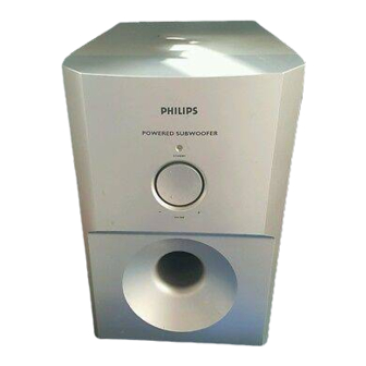
Active Subwoofer
Service
Service
Service
Service
Service
Service Manual
©
Copyright 2002 Philips Consumer Electronics B.V. Eindhoven, The Netherlands
All rights reserved. No part of this publication may be reproduced, stored in a retrieval system or
transmitted, in any form or by any means, electronic, mechanical, photocopying, or otherwise
without the prior permission of Philips.
Published by KC-ET0227 Service Audio Printed in The Netherlands
Version 1.0
TABLE OF CONTENTS
Location of PC Boards/Specifications ........................ 1-2
Specifications .............................................................. 1-2
Measurement Setup ................................................... 1-3
ESD & Safety Instruction ............................................ 1-4
Disassembly Instructions & Service Positions .............. 2
Set Block & Wiring Diagram .......................................... 3
Amplifier, I/P & LED/VR Boards .................................... 4
Mechanical Exploded View & Parts List ........................ 5
Subject to modification
SW3600/
Page
GB
17S
3139 785 30069
Advertisement
Table of Contents

Related Manuals for Philips SW3600/17S


Summary of Contents for Philips SW3600/17S
- Page 1 Mechanical Exploded View & Parts List ......5 © Copyright 2002 Philips Consumer Electronics B.V. Eindhoven, The Netherlands All rights reserved. No part of this publication may be reproduced, stored in a retrieval system or transmitted, in any form or by any means, electronic, mechanical, photocopying, or otherwise without the prior permission of Philips.
-
Page 2: Location Of Pc Boards
LOCATION OF PC BOARDS Amplifier PCB SPECIFICATIONS SUBWOOFER Subwoofer (not magnetically shielded design).......................6.5" Output Power............................50W (4Ω,DIN) THD (Total Harmonic Distortion) ......................10% at 55 Hz Reproduction Frequency Response.......................40 Hz-150 Hz Phase Switch..............................0 ,180 Input Sensitivity (Subwoofer In).........................500 mVrms AC Power ...............................120V / 60 Hz power Consumption......................32 W (at 1/8 Rated Power) Dimensions (w x h x d)....................200 mm x 310mm x 350 mm Weight................................6.8 Kg... -
Page 3: Measurement Setup
MEASUREMENT SETUP... -
Page 4: Esd & Safety Instruction
ESD & SAFETY INSTRUCTION WAARSCHUWING WARNING Alle IC’s en vele andere halfgeleiders zijn All ICs and many other semi-conductors are gevoelig voor electrostatische ontladingen susceptible to electrostatic discharges (ESD). (ESD). Careless handling during repair can reduce life Onzorgvuldig behandelen tijdens reparatie kan drastically. - Page 5 DISASSEMBLY INSTRUCTIONS Dismantling the Grill Base & Speaker Driver 2. Place the Subwoofer Box as shown in the Picture 2 1. Place the Subwoofer Box as shown in the Picture 1 and and loosen 4 screws A to remove the Speaker Driver. use a screw driver to force open the Grill Base.
- Page 6 SERVICE POSITION...
-
Page 7: Set Block Diagram
SET BLOCK DIAGRAM... - Page 8 SET WIRING DIRGRAM I/P PCB...
- Page 9 TDA7296 INTERNAL IC DIAGRAM AMPLIFIER, I/P & LED / VR BOARD TABLE OF CONTENTS Internal IC Diagram............. 4-1 Circuit Diagram ..............4-2 PCB Layout View ..............4-3 Electrical Part list ..............4-4...
-
Page 10: Circuit Diagram
CIRCUIT DIAGRAM IC401 A2 C301 C302 IC502 A4 C304 JK301 C1 C305 LD401 C3 C306 Q352 C307 Q501 C401 Q502 C402 Q503 C403 Q504 C404 Q505 C405 R301 C406 R302 C407 R303 C410 R304 C411 R366 C412 R367 C413 R368 C414 R369 C415... - Page 11 PCB LAYOUT VIEW C301 C405 C509 C520 C908 D501 J103 J506 R301 R372 R411 R524 R901 RB401 B7 J104 C303 C406 C510 C521 C909 D503 JK301 B6 R302 R373 R514 R525 R902 RB402 A7 C304 C407 C511 C522 C910 D901 J105 LD401 C6 R303...
- Page 12 ELECTRICAL PARTS LIST - AMPLIFIER, I/P, LED & VR BOARDS ELECTRICAL PARTS LIST - AMPLIFIER, I/P, LED & VR BOARDS MISCELLANEOUS CN901 9965 000 12617 CONNECTOR 3PIN PITCH=3,96 M C910 4822 124 40207 100uF 20% 25V D901 4822 130 31878 1N4003G C911 2038 554 00065...
- Page 13 SW3600 Ex x ploded Drawing...
- Page 14 MECHANICAL & ACCESSORIES PARTS LIST - MAIN UINT SCREW LIST - MAIN UINT 9965 000 14284 VOLUME KNOB D3 x 8 9965 000 14285 FRONT CAB M4 x 20 9965 000 14286 PORT D3.5 x 14 9965 000 03365 CLOTH (185 X 185MM) D3 x 8 M3 x 14 9965 000 03360...