Table of Contents
Advertisement
Copyright
This publication, including all photographs, illustrations and software, is protected un-
der international copyright laws, with all rights reserved. Neither this manual, nor any
of the material contained herein, may be reproduced without written consent of the au-
thor.
Version 1.0
Disclaimer
The information in this document is subject to change without notice. The manufac-
turer makes no representations or warranties with respect to the contents hereof and
specifically disclaim any implied warranties of merchantability or fitness for any par-
ticular purpose. The manufacturer reserves the right to revise this publication and to
make changes from time to time in the content hereof without obligation of the manu-
facturer to notify any person of such revision or changes.
Trademark Recognition
Microsoft, MS-DOS and Windows are registered trademarks of Microsoft Corp.
MMX, Pentium, Pentium-II, Pentium-III, Celeron are registered trademarks of Intel
Corporation.
Other product names used in this manual are the properties of their respective owners
and are acknowledged.
Federal Communications Commission (FCC)
This equipment has been tested and found to comply with the limits for a Class B digi-
tal device, pursuant to Part 15 of the FCC Rules. These limits are designed to provide
reasonable protection against harmful interference in a residential installation. This
equipment generates, uses, and can radiate radio frequency energy and, if not in-
stalled and used in accordance with the instructions, may cause harmful interference
to radio communications. However, there is no guarantee that interference will not oc-
cur in a particular installation. If this equipment does cause harmful interference to
radio or television reception, which can be determined by turning the equipment off
and on, the user is encouraged to try to correct the interference by one or more of the
following measures:
−
Reorient or relocate the receiving antenna.
−
Increase the separation between the equipment and the receiver.
−
Connect the equipment onto an outlet on a circuit different from that to which
the receiver is connected.
−
Consult the dealer or an experienced radio/TV technician for help.
Copyright © 2002
All Rights Reserved
VT8754/August 2002
i
Preface
MS9127C, V1.0
Advertisement
Table of Contents

Related Manuals for MATSONIC MS9127C


Summary of Contents for MATSONIC MS9127C
- Page 1 − Connect the equipment onto an outlet on a circuit different from that to which the receiver is connected. − Consult the dealer or an experienced radio/TV technician for help. Copyright © 2002 All Rights Reserved MS9127C, V1.0 VT8754/August 2002...
- Page 2 Shielded interconnect cables and a shielded AC power cable must be employed with this equipment to ensure compliance with the pertinent RF emission limits governing this device. Changes or modifications not expressly approved by the system's manu- facturer could void the user's authority to operate the equipment. Declaration of Conformity This device complies with part 15 of the FCC rules.
-
Page 3: Table Of Contents
Preface CHAPTER 1 Introducing the Mainboard Introduction ....................3 Checklist .....................3 Standard Items ....................3 Features .....................3 Choosing a Computer Case ...............3 Mainboard Components ................3 CHAPTER 2 Installing the Mainboard Safety Precautions..................3 Quick Guide ....................3 Installing the Mainboard in a Case..............3 Checking Jumper Settings ................3 Setting Jumpers .................... - Page 4 Integrated Peripherals ..................3 Power Management Setup ................3 PNP/PCI Configurations.................. 3 PC Health Status....................3 Frequency/Voltage Control................3 Load Fail-Safe Defaults................. 50 Load Optimized Defaults................50 Set Supervisor/User Password................. 3 Save & Exit Setup ................... 3 Exit Without Saving ..................3 錯誤! 尚未定義書籤。...
-
Page 5: Introducing The Mainboard
VIA VT8754 Northbridge and VT8235 Southbridge chipsets which delivers workstation level performance. The MS9127C comes with a full set of I/O features conveniently integrated on the rear I/O panel, including support for PS/2 keyboard and mouse connectors, Six USB ports (Four back-panel USB 2.0 ports, onboard USB headers provid-... -
Page 6: Features
Processor The MS9127C mainboard includes a mPGA Socket 478 that has the following features: • Supports up to a 400/533 MHz front side bus (FSB) • Accommodates Intel Pentium 4 processors Chipset The chipset on MS9127C includes the VT8754 Northbridge... - Page 7 • Two IDE connectors which support four IDE channels and a floppy disk drive interface The MS9127C is capable of Ultra DMA bus mastering with transfer rates of 33/66/100/133 MB/sec. 10/100 LAN The VT6103 is a Physical Layer device for Ethernet 10BASE-T...
-
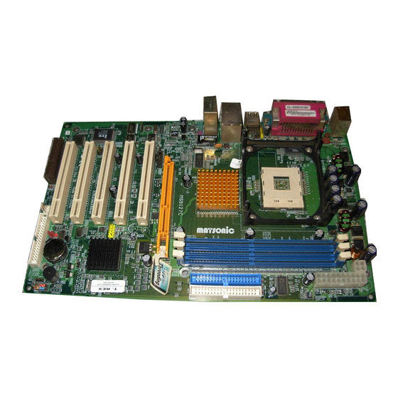
Page 8: Choosing A Computer Case
There are many types of computer cases on the market. The mainboard com- plies with the specifications for the ATX system case. Some features on the mainboard are implemented by cabling connectors on the mainboard to indi- cators and switches on the system case. Ensure that your case supports all the features required. - Page 10 Table of Mainboard Components Label Component AGP1 Accelerated Graphics Port ATX1 Standard 20-pin ATX power connector ATX2 Power connector AUDIO1 Mic/speaker-out connector Three volt realtime clock battery CASFAN1 Auxiliary case cooling fan Primary CD-in connector (Sony) Secondary CD-in connector (Panasonic) CNR1 Communications Networking Riser slot CPU SOCKET...
-
Page 11: Installing The Mainboard
Installing the Mainboard Follow these safety precautions when installing the mainboard: • Wear a grounding strap attached to a grounded device to avoid damage from static electricity. • Discharge static electricity by touching the metal case of a safely grounded object before working on the mainboard. •... - Page 12 Refer to the following illustration and instructions for installing the mainboard in a case: This illustration shows an ex- 2. Secure the mainboard with ample of a mainboard being screws where appropriate. installed in a tower-type case: Note: Do not overtighten the screws as this can stress the main- board.
-
Page 13: Checking Jumper Settings
Checking Jumper Settings The following illustration shows the location of the mainboard jumpers. Pin 1 is labeled. Jumper Settings Jumper Type Description Setting (default) 3 pin Clear CMOS 1-2: Normal jumper 2-3: Clear CMOS 3 pin CPU bus speed 1-2: Auto select jumper 2-3: 533 MHz JP1 - This jumper enables you to reset BIOS. -
Page 14: Connecting Case Components
After you have installed the mainboard into a case, you can begin connecting the mainboard components. Refer to the following: Connect the Pentium 4 processor auxiliary case power supply connector to ATX2. Connect the standard power supply connec- tor to ATX1. Connect the CPU cooling fan cable to CPUFAN1. - Page 15 CPUFAN1/CASFAN1: FAN Power Connectors Signal Name Function System Ground +12V Power +12V Sense Sensor SJ1: Single color LED header Signal Name Function ACPI LED MSG LED (-) green ACPI LED MSG LED (-) green SB5V Power LED (+) ACPI LED function: S4/S5 Light Blinking...
-
Page 16: Front Panel Connector
Front Panel Connector The front panel connector (PANEL1) provides a standard set of switch and LED connectors commonly found on ATX or micro-ATX cases. Refer to the table below for information: Signal Name Function HD_LED_P Hard disk LED pull up (330 ohm) to +5V FP PWR/SLP MSG LED pull up (330 ohm) to +5V HD_LED_N... -
Page 17: Installing Hardware
Reserved (do not use) No pin Hard Drive Activity LED Connecting pins 1 and 3 to a front panel mounted LED provides visual indica- tion that data is being read from or written to the hard drive. For the LED to function properly, an IDE drive should be connected to the onboard IDE inter- face. -
Page 18: Cpu Installation Procedure
Avoid using cooling fans with sharp edges on the fan casing and the clips. Also, install the cooling fan in a well-lit work area so that you can clearly see the mainboard and processor socket. Before installing the Processor This mainboard automatically determines the CPU clock frequency and sys- tem bus frequency for the processor. - Page 19 Note: The pin-1 corner is marked with an arrow Follow these instructions to install the Retention Module and CPU: Remove the existing retention module (if applicable). Position the backplate against the underside of the mainboard; secure the 4 screws firmly on the retention module.
- Page 20 Locate the CPU cut edge (the corner with the pinhole noticeably miss- ing). Align and insert the CPU correctly. Press the lever down. Apply thermal grease on top of the CPU. Put the CPU Fan down on the retention module and snap the four reten- tion legs of the cooling fan into place.
-
Page 21: Installing Memory Modules
Installing Memory Modules This mainboard accommodates 184-pin 2.5V unbuffered Double Data Rate (DDR) SDRAM memory modules. The memory chips must be standard or registered SDRAM (Synchronous Dynamic Random Access Memory). The memory bus can run at 100/133/166 MHz. If your processor operates over a 100 MHz system bus, you can install DDR200 or DDR266/DDR333 memory modules that operate over a 100/133/166 MHz memory bus. -
Page 22: Installing A Hard Disk Drive/Cd-Rom
DDR SDRAM memory module table: DDR 266 3 DIMMS DDR 333 3 DIMMS DDR 400 2 DIMMS Note: We do not guarantee that all DDR 400 memory modules will work prop- erly with your mainboard. Installing a Hard Disk Drive/CD-ROM This section describes how to install IDE devices such as a hard disk drive and a CD-ROM drive. - Page 23 Plug an IDE cable connector into the hard disk drive IDE connector (B). It doesn't matter which connector on the cable you use. Plug a power cable from the case power supply into the power connector on the hard disk drive (C). When you first start up your system, the BIOS should automatically detect your hard disk drive.
-
Page 24: Installing A Floppy Diskette Drive
Installing a Floppy Diskette Drive The mainboard has a floppy diskette drive (FDD) interface and ships with a diskette drive ribbon cable that supports one or two floppy diskette drives. You can install a 5.25-inch drive and a 3.5-inch drive with various capacities. The floppy diskette drive cable has one type of connector for a 5.25-inch drive and another type of connector for a 3.5-inch drive. -
Page 25: Installing Add-On Cards
Installing Add-on Cards This mainboard has five 32-bit PCI (Peripheral Components Interconnect) expansion slots, one 8xAGP slot, and one Communications and Networking Riser (CNR) slot. PCI Slots PCI slots are used to install expansion cards that have the 32-bit PCI interface. 8xAGP Slot The 8xAGP slot is used to install a graphics adapter that supports the universal AGP 3.0 specification and has a 1.5V-keyed connec-... - Page 26 Follow these instructions to install an add-on card: Remove a blanking plate from the system case corresponding to the slot you are going to use. Install the 1.5V-keyed connector of the add-on card into the ex- pansion slot. Ensure that the edge connector is correctly seated in the slot.
-
Page 27: Connecting Optional Devices
Connecting Optional Devices Refer to the following for information on connecting the mainboard’s optional devices: AUDIO1: Front Panel Audio header This header allows the user to install auxiliary front-oriented microphone and line-out ports for easier access. Signal Name Function AUD_MIC Front Panel Microphone input signal AUD_GND Ground used by Analog Audio Circuits... - Page 28 USB3: Front panel USB connectors The mainboard has two USB ports installed on the rear edge I/O port array. Additionally, some computer cases have USB ports at the front of the case. If you have this kind of case, use auxiliary USB connector USB3 to connect the front-mounted ports to the mainboard.
- Page 29 SPDIFO1: SPDIF out header You can purchase an optional 24-bit digital audio extension bracket from a third-party vendor. You can use the audio RCA jacks to connect to digital audio devices. If your CD-ROM/DVD drive has digital audio output, you can connect it to the input pins of the SPDIF connector.
-
Page 30: External Connector Color Coding
The backplane of the mainboard has the following I/O ports: PS/2 Mouse Use the upper PS/2 port to connect a PS/2 pointing device. PS/2 Keyboard Use the lower PS/2 port to connect a PS/2 keyboard. LPT1 Use LPT1 to connect printers or other parallel communica- tions devices. -
Page 31: Using Bios
Using BIOS The computer uses the latest Award BIOS with support for Windows Plug and Play. The CMOS chip on the mainboard contains the ROM setup instructions for configuring the mainboard BIOS. The BIOS (Basic Input and Output System) Setup Utility displays the system's configuration status and provides you with options to set system parameters. -
Page 32: Entering The Setup Utility
Entering the Setup Utility When you power on the system, BIOS enters the Power-On Self Test (POST) routines. POST is a series of built-in diagnostics performed by the BIOS. After the POST routines are completed, the following message appears: Press DEL to enter SETUP Pressing the delete key accesses the BIOS Setup Utility: Phoenix –... -
Page 33: Using Bios
If your mainboard has an item called Firmware Write Protect in Advanced BIOS features, disable it. (Firmware Write Protect prevents BIOS from being overwritten.) Create a bootable system disk. (Refer to Windows online help for infor- mation on creating a bootable system disk.) Download the Flash Utility and new BIOS file from the manufacturer's Web site. -
Page 34: Standard Cmos Features
Standard CMOS Features This option displays basic information about your system. Phoenix – AwardBIOS CMOS Setup Utility Standard CMOS Features Item Help Date (mm:dd:yy) Tue, July 11 2001 Time (hh:mm:ss) 12 : 8 : 59 Menu Level IDE Primary Master Change the day, month, IDE Primary Slave year and century. - Page 35 IDE HDD Auto-Detection Press <Enter> while this item is highlighted to prompt the Setup Utility to automatically detect and configure an IDE device on the IDE channel. Note: If you are setting up a new hard disk drive that supports LBA mode, more than one line will appear in the parameter box.
-
Page 36: Advanced Bios Features
Advanced BIOS Features This option defines advanced information about your system. Phoenix – AwardBIOS CMOS Setup Utility Advanced BIOS Features Item Help CPU L1 & L2 Cache [Enabled] CPU L2 Cache ECC Checking [Enabled] Menu Level Quick Power On Self Test [Enabled] First Boot Device [Floppy]... - Page 37 Swap Floppy Drive (Disabled) If you have two floppy diskette drives in your system, this item allows you to swap the assigned drive letters so that drive A becomes drive B, and drive B becomes drive A. Boot Up Floppy Seek (Disabled) If this item is enabled, it checks the size of the floppy disk drives at start-up time.
-
Page 38: Advanced Chipset Features
Video BIOS Shadow (Enabled) This function, when enabled allows VGA BIOS to be copied to the system DRAM for enhanced performance. Small Logo (EPA) Show (Disabled) Determines whether or not the EPA logo appears during boot up. Advanced Chipset Features These items define critical timing parameters of the mainboard. - Page 39 Current FSB Frequency This item displays the frontside bus (FSB) frequency. This is a display-only item. You cannot make changes to this field. Current DRAM Frequency This item displays the memory (DRAM) frequency. This is a display-only item. You cannot make changes to this field. DRAM Clock (By SPD) This item enables you to manually set the DRAM Clock.
- Page 40 that you leave this item at the default value. DRAM Burst Len (4) This item describes which burst lengths are supported by the devices on the mainboard. Write Recovery Time (3T) This item controls the timing between write and precharge command. Press <Esc>...
- Page 41 AGP Fast Write (Disabled) This item lets you enable or disable the caching of display data for the video memory of the processor. Enabling this item can greatly improve the display speed. Disable this item if your graphics display card does not support this feature.
-
Page 42: Integrated Peripherals
Memory Hole (Disabled) This item is used to reserve memory space for ISA expansion cards that re- quire it. System BIOS/Video RAM Cacheable (Disabled) These items allow the video and system to be cached in memory for faster execution. Leave these items at the default value for better performance. Delay Prior to Thermal (16 Min) Enables you to set the delay time before the CPU enters auto thermal mode. - Page 43 VIA OnChip IDE Device Scroll to this item and press <Enter> to view the following screen: Phoenix – AwardBIOS CMOS Setup Utility VIA OnChip IDE Device OnChip IDE Channel0 [Enabled] Item Help OnChip IDE Channel1 [Enabled] Menu Level IDE Prefetch Mode [Enabled] Primary Master [Auto]...
- Page 44 VIA OnChip PCI Device Scroll to this item and press <Enter> to view the following screen: Phoenix – AwardBIOS CMOS Setup Utility VIA OnChip PCI Device Item Help VIA-3058 AC97 Audio [Auto] VIA-3068 MC97 Modem [Auto] Menu Level Onboard LAN Device [Enabled] Onboard LAN Boot ROM [Disabled]...
- Page 45 SuperIO Device Scroll to this item and press <Enter> to view the following screen: Phoenix – AwardBIOS CMOS Setup Utility SuperIO Device Item Help Onboard FDC Controller [Enabled] Onboard Serial Port 1 [3F8/IRQ4] Menu Level Onboard Serial Port 2 [2F8/IRQ3] UART Mode Select [Normal] UR2 Duplex Mode...
- Page 46 Parallel Port Mode (ECP) Enables you to set the data transfer protocol for your parallel port. There are four options: SPP (Standard Parallel Port), EPP (Enhanced Parallel Port), ECP (Extended Capabilities Port) and ECP+EPP. SPP allows data output only. Extended Capabilities Port (ECP) and Enhanced Parallel Port (EPP) are bi-directional modes, allowing both data input and out- put.
-
Page 47: Power Management Setup
Power Management Setup This option lets you control system power management. The system has vari- ous power-saving modes including powering down the hard disk, turning off the video, suspending to RAM, and software power down that allows the sys- tem to be automatically resumed by certain events. Power Management Timeouts The power-saving modes can be controlled by timeouts. - Page 48 timeouts. If this item is set to Max Saving, power-saving modes occur after a short timeout. If this item is set to Min Saving, power-saving modes occur after a longer timeout. If the item is set to User Define, you can insert your own timeouts for the power-saving modes.
- Page 49 IRQ/Event Activity Detect Scroll to this item and press <Enter> to view the following screen: Phoenix – AwardBIOS CMOS Setup Utility IRQ/Event Activity Detect Item Help [OFF] LPT & COM [LPT/COM] Menu Level HDD & FDD [ON] PCI Master [OFF] PowerOn by PCI Card [Enabled] Wake Up On LAN/Ring...
-
Page 50: Pnp/Pci Configurations
your system every day at the specified time. Press <Esc> to return to the Power Management screen. IRQs Activity Monitoring Scroll to this item and press <Enter> to view the following screen: Phoenix – AwardBIOS CMOS Setup Utility IRQs Activity Monitoring Primary INTR [ON] Item Help... - Page 51 These options configure how PnP (Plug and Play) and PCI expansion cards oper- ate in your system. Both the ISA and PCI buses on the Mainboard use system IRQs (Interrupt ReQuests) and DMAs (Direct Memory Access). You must set up the IRQ and DMA assignments correctly through the PnP/PCI Configurations Setup utility for the mainboard to work properly.
- Page 52 IRQ Resources The submenu allows you to individually assign an interrupt type for interrupts IRQ-3 to IRQ-15. Phoenix – AwardBIOS CMOS Setup Utility PnP/PCI Configurations Item IRQ-3 assigned to [PCI Device] IRQ-4 assigned to [PCI Device] Menu Level IRQ-5 assigned to [PCI Device] IRQ-7 assigned to [PCI Device]...
-
Page 53: Pc Health Status
PC Health Status On mainboards that support hardware monitoring, this item lets you monitor the parameters for critical voltages, critical temperatures, and fan speeds: Phoenix – AwardBIOS CMOS Setup Utility PC Health Status Item Help Shutdown Temperature [Disabled] CPU VCORE Menu Level 2.50V 3.30V... -
Page 54: Load Fail-Safe Defaults
CPU Ratio Use this item to select a multiplier for the system frontside bus (FSB) fre- quency. The value of the multiplier must be set so that: Multiplier x Frontside Bus Frequency = CPU Clock Speed For example, if you have a processor that is rated to run at 450 MHz and the system is running a frontside bus frequency of 100 MHz, you should select a multiplier of 4.5 so that: 4.5 (Multiplier) x 100 MHz (frontside bus) = 450 MHz (CPU clock) -
Page 55: Set Supervisor/User Password
Set Supervisor/User Password When this function is selected, the following message appears at the center of the screen to assist you in creating a password. ENTER PASSWORD Type the password, up to eight characters, and press <Enter>. The password typed now will clear any previously entered password from CMOS memory. You will be asked to confirm the password. -
Page 56: Using The Mainboard Software
Using the Mainboard Software The support software CD-ROM that is included in the mainboard package contains all the drivers and utility programs needed to properly run the bun- dled products. Below you can find a brief description of each software program, and the location for your mainboard version. - Page 57 All the utility software available on the CD-ROM is Windows compliant. It is provided only for the convenience of customers. The following software is furnished under license and may only be used or copied in accordance with the terms of the license. Note: The software in these folders is subject to change at anytime without prior notice.
-
Page 58: Recovery Genius
CD Ghost The CD Ghost software enables you to create a virtual cabinet of CD-ROM drives on your system to help you categorize and organize your CD collection. A user-friendly interface assists you in quickly creating images of both CDs and DVDs onto your system.
Need help?
Do you have a question about the MS9127C and is the answer not in the manual?
Questions and answers