Table of Contents
Advertisement
Quick Links
Advertisement
Table of Contents

Subscribe to Our Youtube Channel
Related Manuals for TracVision A9


Summary of Contents for TracVision A9
- Page 1 TracVision ® Installation Guide...
-
Page 2: Table Of Contents
(Mon.-Fri., 9 am-6 pm; Sat., 9 am-2 pm ET, -5 GMT) KVH and TracVision are registered trademarks of KVH Industries, Inc. All other trademarks are property of their respective companies. The information in this document is subject to change without notice. No company shall be liable for errors contained herein. -
Page 3: Important Safety Information
CAUTION Avoid Driver Distraction Do not connect the TracVision system to video screens that are visible to the vehicle driver. Driver distraction can result in an accident with personal injury or death resulting. -
Page 4: Inspect Parts And Get Tools
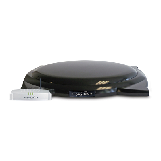
Inspect Parts and Get Tools Before you begin, follow these steps to ensure Figure 1: TracVision A9 System Components you have everything needed to complete the installation. a. Unpack the box and ensure it contains everything shown on the Kitpack Contents List. -
Page 5: Mount The Antenna
Mount the Antenna To mount the antenna, first remove the shipping Figure 3: Shipping Restraint Locations on Antenna Base restraints with heavy-duty wire cutters (see Figure 3). Then follow the steps for your particular mounting option: Rack Mount ....see below Roof Mount . - Page 6 Continued Mount the Antenna With an assistant’s help, gently place the Figure 6: Placing the Antenna on the Crossbars antenna onto the roof rack with the cable connector facing the rear of the vehicle. All four brackets should rest on top of the roof rack’s crossbars (see Figure 6 and Figure 7).
- Page 7 Continued Mount the Antenna With the cushions installed in the brackets, Figure 8: Positioning Rubber Cushions For Best Fit the bottom of the antenna should rest above the vehicle’s roof. If the antenna’s base touches the roof, you will need to add a spacer under each bracket to raise the antenna higher off the crossbars.
- Page 8 Continued Mount the Antenna Secure each mounting bracket to the roof Figure 11: Securing the Brackets to the Crossbars rack with a retaining plate, two hex socket screws, and two jam nuts (supplied in kit). Use Cover a 1.75" screw at the end of each bracket and use a 2"...
- Page 9 Continued Mount the Antenna If you are mounting the antenna directly to the Figure 13: Attaching the Mounting Brackets roof, follow the steps below. Mount the Antenna Directly to the Roof Factory-installed bolt Attach each of the four mounting brackets to the antenna base using two 1/4 "-20 x 3/4 "...
- Page 10 Continued Mount the Antenna With an assistant’s help, position the antenna Figure 16: Positioning an Antenna Bracket Onto a Mounting Block onto the centerline of the vehicle’s roof with a mounting block and mounting plate under each bracket (see Figure 16). Make sure the antenna’s connector faces the rear of the vehicle.
- Page 11 Continued Mount the Antenna Seal all fasteners with silicone sealant or Figure 19: Securing the Antenna to the Roof equivalent. Cover Place the rubber mounting blocks back onto the mounting plates. 2.5" Place the antenna onto the mounting blocks. Hex Socket Screws Align the holes in the antenna brackets with 2.25"...
-
Page 12: Wire The Antenna
Wire the Antenna To wire the antenna, first route the antenna cable. Figure 21: Connecting the Antenna Cable to the Antenna You can route the antenna cable directly through the roof or from behind the hatch (SUVs and minivans) by following these steps: Roof Routing . - Page 13 Continued Wire the Antenna Choose a location on the roof for the Figure 22: Locating the Cable Access and Fitting Mounting Holes 1/2 " (12.7 mm) diameter cable access hole. Inside the vehicle, remove the headliner to access the underside of the roof where you will be cutting out the hole.
- Page 14 Continued Wire the Antenna Move the fitting down the cable until it covers Figure 24: Fitting Mounted to Roof the cable access hole, flush to the vehicle’s roof. Line up the fitting’s three mounting holes with the three 5/32 " holes drilled in the roof. Apply silicone sealant or equivalent to the holes and insert the supplied #6-32 x 5/8 "...
- Page 15 Continued Wire the Antenna Route the Cable Behind the Hatch Figure 27: Cable Routed Behind Rear Hatch If the gap in the vehicle’s hatch hinge is wide enough when closed to allow the antenna cable to pass without pinching it, maintaining a 4.5"...
- Page 16 Continued Wire the Antenna Connect and SLOWLY hand-tighten the Figure 28: Connecting the Antenna Cable to the Antenna antenna cable to the antenna, allowing the grease to diffuse and settle into the entire space within the connector. Make sure the antenna cable is hand- tightened all the way into the connector.
-
Page 17: Plan The Tv-Hub Installation
Plan the TV-Hub Installation Consider the following TV-Hub installation Figure 29: TV-Hub Dimensions - Horizontal Orientation guidelines. LED Lights • Select a mounting location in a dry, well- ventilated area inside the vehicle away from 4.36" any heat sources. (11.1 cm) 1.73"... -
Page 18: Mount The Tv-Hub
Mount the TV-Hub Follow these steps to install the TV-Hub inside Figure 31: TV-Hub Mounting Template the vehicle: Front of TV-Hub a. Tape the mounting template in the location 7.93" Keyhole selected for the TV-Hub. Punch holes at each (20.1 cm) 2 x Ø... -
Page 19: Wire The Antenna To The Tv-Hub
Wire the Antenna to the TV-Hub Follow these steps to connect the antenna to the Figure 33: TV-Hub Antenna Connection TV-Hub. Antenna IMPORTANT! Be sure to leave an adequate service loop, approximately 8" (20 cm) of slack, in the cable Antenna Cable for easy serviceability. -
Page 20: Wire The Receivers
Wire the Receivers The steps for connecting the customer’s Figure 35: TV-Hub Receiver Connections receiver(s) to the TracVision system and setting them up depends upon the customer’s satellite TV service (see Figure 35). Follow the steps in the applicable section below TV-Hub to wire the receivers. - Page 21 DIRECTV – SWM Wiring Figure 36: Wiring 1 DIRECTV SWM Receiver Follow these steps to connect DIRECTV SWM Antenna receivers to the TracVision system. NOTE: You can connect non-SWM receivers as well, as explained in “DIRECTV – Non-SWM Wiring” on...
- Page 22 Wire the Receivers DIRECTV – Non-SWM Wiring Figure 38: Wiring 1 to 2 DIRECTV Non-SWM Receivers Follow these steps to connect non-SWM receivers Antenna to the TracVision system. IMPORTANT! Non-SWM receivers are limited to manual Antenna Cable satellite switching only.
- Page 23 Wire the Receivers DISH Network Wiring Figure 40: Wiring 1 DISH Receiver Follow these steps to connect DISH Network Antenna receivers to the TracVision system. IMPORTANT! Receivers must be DISH Pro-compatible. Look Antenna Cable for the DISH Pro logo on the box.
-
Page 24: Connect Power
Before connecting power, be sure the vehicle is Figure 43: TV-Hub Grounding Connection properly grounded. Grounding Requirements Proper grounding of the TracVision system to the Ground vehicle’s ground is critically important, as it protects the equipment from lightning and TV-Hub electrostatic discharges (ESD). - Page 25 Continued Connect Power Connect Power to the System Figure 44: TracVision System Power NOTE: When powering up a SWM configuration, apply power to all other system components before powering up the receivers and DVRs (tuners are assigned SWM channels during startup).
-
Page 26: Turn On The System
Ensure the antenna has a clear, unobstructed view of the sky. Power Switch b. Press the power switch on the rear panel of the TV-Hub to apply power to the TracVision system (see Figure 45). TV-Hub c. Within a few minutes, the TV-Hub and Power lights should be lit green (the Antenna light will be flashing green). -
Page 27: Access The Web Interface
Access the Web Interface Follow the steps for either option below to access Figure 46: Wi-Fi Connection the TV-Hub’s web interface. Using the Wireless Connection a. Select the TVHub-<TV-Hub serial number> network from your device’s Wi-Fi settings to connect to the TV-Hub (see Figure 46). TV-Hub b. -
Page 28: Connect To An Existing Network
Connect to an Existing Network Optional Connecting the TV-Hub to a vehicle’s local area network (LAN) is required if any of the following Figure 48: TV-Hub Network Connections conditions apply: • One or more IP AutoSwitches are installed to enable automatic satellite switching (DISH Network only) TV-Hub •... -
Page 29: Secure The Wi-Fi Connection
Secure the Wi-Fi Connection By default, the TV-Hub’s wireless settings are Figure 51: TV-Hub Security and Password Setting configured for the following: • Wireless Mode: AP (Access Point) • SSID: TV-Hub-<TV-Hub serial number> • IP Address: 172.16.0.1 • Security Mode: Off KVH strongly advises that you select the WPA_PSK security mode as shown in Figure 51 and assign a unique password to prevent... -
Page 30: Set Up The System
Set Up the System The Setup Wizard appears upon initial startup to Figure 52: Setup Wizard Welcome Page step you through system configuration (see Figure 52). Before you begin to set up the system: • Know the service provider and associated satellite(s) •... - Page 31 Continued Set Up the System Setup Wizard Figure 54: Compatible Preset Satellite Groups System configuration continues by prompting Service Satellites (A-B-C-D) you to enter information or perform specific tasks, as necessary. For example: DIRECTV U.S. DIRECTV Dual: 101W and 119W •...
-
Page 32: Educate The Customer
Educate the Customer Before you leave the vehicle, test the system to Figure 55: Satellite Switching Selection on Home Page ensure the antenna works properly. Fill out the Installation Checklist (provided in the Welcome Kit) and return it to KVH. Refer to the instructions on the form. - Page 33 TV. Common causes of blockage include trees, buildings, bridges, overpasses, and mountains (see Figure 57). The TracVision system will not work inside a garage. Heavy rain or snow might also temporarily interrupt reception. • Clean the antenna regularly. Dirt buildup can affect satellite TV reception.
-
Page 34: Installing An Ip Autoswitch
Installing an IP AutoSwitch Appendix Follow these steps to add an IP AutoSwitch (KVH part no. 72-0634) to each DISH Network receiver you want to be able to control satellite Figure 58: IP AutoSwitch selection in Automatic satellite switching mode. NOTE: A receiver connected directly to the TV-Hub’s “Receiver”... - Page 35 Continued Installing an IP AutoSwitch Wire the IP AutoSwitch Figure 60: IP AutoSwitch Connections The wiring of the IP AutoSwitch depends on the RF Input** specific configuration. Refer to the wiring diagrams provided in “DISH Network Wiring” on page 22, while following the general wiring RF In steps below: Network...
- Page 36 Continued Installing an IP AutoSwitch Configure the IP AutoSwitch Figure 61: Add IP AutoSwitch Screen When performing system setup (see “Set Up the System” on page 29), follow these additional steps to configure the IP AutoSwitch. NOTE: KVH recommends that you run the Setup Wizard in the web interface whenever you change your system’s configuration by adding or removing Television 2...
-
Page 37: Using A Directv Coax Network
Using a DIRECTV Coax Network Appendix In Automatic satellite switching mode, the TV-Hub can accept commands from the master SWM-compatible DIRECTV receiver to Figure 63: Non-Genie Configuration automatically switch between the 101W and TV-Hub 119W satellites. The TV-Hub communicates with Ethernet the master receiver via the TV-Hub’s Ethernet port link to the DIRECTV coax network. - Page 38 Continued Using a DIRECTV Coax Network Genie Configurations Figure 64: Genie Configuration Full DECA Broadband functionality is built into TV-Hub Genie DVRs (HR44 or HR34). So if a Genie DVR Ethernet is present on the DIRECTV SWM network, no external DECA Broadband kit is required. Just connect the Genie's Ethernet port to the TV-Hub's Can connect via an Ethernet port, either directly or via an onboard...
- Page 39 Continued Using a DIRECTV Coax Network Additional Equipment for Older Receivers Figure 65: Additional Equipment for Older Receivers In addition to the DECA Broadband Kit or a Genie DVR, you might need to connect an SWM Splitter additional device in-line between the receiver and the SWM splitter, depending on the model (see Figure 65).
- Page 40 Configuring the DIRECTV Receivers for Figure 66: IP Addressing for Automatic Switching (Example) Automatic Switching To establish communications between the TracVision system and each SWM-compatible TV-Hub DIRECTV receiver for automatic satellite switching, you need to set each receiver to a static...
- Page 41 Continued Using a DIRECTV Coax Network Assigning Static IP Addresses to DIRECTV Receivers Figure 68: IP Address on a DIRECTV Receiver (Example) Once you have identified a valid static IP address WITHOUT an Onboard Network (No Router) range for the receivers, follow these steps to assign a unique static IP address within that range to each receiver.
- Page 42 Continued Using a DIRECTV Coax Network Add the new receivers to the Autoswitch Figure 69: Adding a DIRECTV Receiver to the Autoswitch Page page of the web interface. Enter each receiver’s static IP address and assign it a friendly name (e.g., “Television 2”) (see Figure 69).
- Page 43 www.kvh.com KVH Industries A/S KVH Industries, Inc. KVH Industries Pte Ltd. EMEA Headquarters World Headquarters Asia-Pacific Headquarters Kokkedal, Denmark Middletown, RI U.S.A. Singapore Tel: +45 45 160 180 Fax: +45 45 160 181 Tel: +1 401 847 3327 Fax: +1 401 849 0045 Tel: +65 6513 0290 Fax: +65 6472 3469 E-mail: info@emea.kvh.com E-mail: info@kvh.com...
Need help?
Do you have a question about the A9 and is the answer not in the manual?
Questions and answers