Table of Contents
Advertisement
Quick Links
COMMERCIAL CLEANING EQUIPMENT
www.tomcatequip.com
1711 South Street
Racine, WI 53404 (USA)
(800) 450-9824 | (+001) 262-681-6470
© 2015 RPS Corporation
Operating Instructions (EN)
Read these Instructions before
using the machine.
Read these Safety Messages
before using the machine.
VERSION 15.246
VR-OP-EN
Advertisement
Table of Contents

Related Manuals for Tomcat VR

Summary of Contents for Tomcat VR
- Page 1 COMMERCIAL CLEANING EQUIPMENT Operating Instructions (EN) Read these Instructions before using the machine. Read these Safety Messages before using the machine. www.tomcatequip.com 1711 South Street Racine, WI 53404 (USA) (800) 450-9824 | (+001) 262-681-6470 VERSION 15.246 © 2015 RPS Corporation VR-OP-EN...
-
Page 2: Introduction
INTRODUCTION This manual is furnished with each new machine. This manual will allow the Operator to get the best performance out of your RPS manufactured Scrubber-Drier, Sweeper, Burnisher, or Orbital Scrubber. Read this manual thoroughly before operating or servicing the machine. This machine will provide excellent performance, but the best results will be obtained at the most minimum costs if: •... -
Page 3: Table Of Contents
Weekly Maintenance: Machine Components Monthly maintenance: Yearly Maintenance: Machine Components Storing Machine: Checking Battery Specifi c Gravity: Machine Setup VR PM Records Un-Crating Machine: Connecting Batteries: Trouble-shooting Installing Main Broom: Installing Side Brooms: Machine Specs Adjusting Side Brooms: Machine Operation... -
Page 4: Safety Messages
SAFETY MESSAGES You will see four kinds of safety reminders in this manual: DANGER DANGER indicates a hazardous situation which, if not avoided, will result in death or serious injury. WARNING WARNING indicates a potentially hazardous situation which, if not avoided, could result in death or serious injury. - Page 5 WARNING WARNING The Batteries in this machine produce hazardous Do not remove, paint over or destroy warning decals. If voltage which can cause electrical shock, burns and/ warning decals become damaged, call 1-262-681-3583 or electrocution. Always disconnect Batteries before for free replacements. servicing this machine.
-
Page 6: Safety Label Locations
SAFETY LABEL LOCATIONS Read and obey all Safety Labels on your VR Floor Sweeper. If you have questions about these labels, ask your supervi- sor. These images indicate where on the VR Safety Labels are located. If ever the labels become illegible, worn off, or torn, promptly report it to your supervisor and replace it. -
Page 7: Operation Controls
OPERATION CONTROLS CIRCUIT BREAKER: 15 AMP resettable circuit breaker CIRCUIT BREAKER: 15 AMP resettable circuit breaker CIRCUIT BREAKER: 10 AMP Side Broom resettable circuit breaker CIRCUIT BREAKER: 40 AMP Main Broom resettable circuit breaker KEY SWITCH: Turns power of the machine ON and OFF EMERGENCY STOP (OPTIONAL): 1 button push machine shut down in case of emergency TR-OP-EN - 7 -... -
Page 8: Operation Controls
OPERATION CONTROLS SIDE BROOM SPEED CONTROL KNOB: Controls the speed of the Side Brooms - Turn counterclockwise to reduce speed FILTER SHAKER SWITCH: Filter shaker button shakes fi lter to remove dust or debris particles to deposit into the hopper for removal BRUSH AMP GAUGE: Indicates the amount of amperage that the Main Broom pulling BATTERY GAUGE / HOUR METER: Indicates the amount of batery charge remaining along with total hours used... -
Page 9: Operation Controls
OPERATION CONTROLS OPPOSITE SIDE OF STEERING PEDESTAL SIDE BROOM LIFT LEVER: Lifts and lowers Side Brooms that allow for debris clean up directly up to walls ADJUSTABLE SEAT WITH ARM RESTS: The machine is equipped with an ergonomic seat with adjustable arm rests and positioning MAIN BROOM LIFT LEVER: Lifts and lowers the Main Broom STEERING WHEEL: Steers the main Drive Wheel HORN: Sounds the horn for warning oncoming traffi... -
Page 10: Machine Components
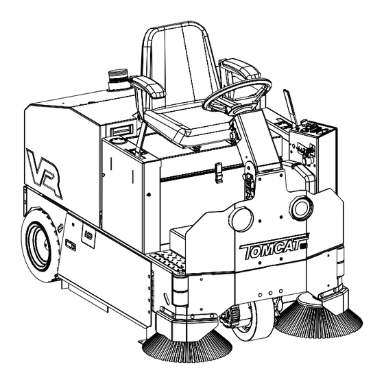
MACHINE COMPONENTS 1. STROBE LIGHT (OPTIONAL): Optional Strobe Light silently alerts others nearby of the machines presence 2. HEADLIGHTS: Helps you see in low light areas and to warn oncoming traffi c 3. SIDE BROOM GUARDS (OPTIONAL): Optional Side Broom Guards protect your Side Broom Brushes in case operator error 4. -
Page 11: Machine Components
MACHINE COMPONENTS 1. FILTER MOTOR: Powers the Beater Bar to clean out the fi lter 2. MAIN BROOM MOTOR: Powers the Main Broom and creates vacuum for the Filter Box 3. ONBOARD CHARGER: Easily charge your machine by conveniently pulling over and plugging in into any standard wall outlet to charge 4. -
Page 12: Machine Setup
MACHINE SETUP UN-CRATING MACHINE: INSTALLING MAIN BROOM: 1. Turn Key Switch to the OFF position and remove Key. Carefully check the crate for any signs of damage and that 2. Open Side Access Door and remove bolt holding Idler the batteries are in the unit. Arm in place (A) (SEE BELOW). -
Page 13: Installing Side Brooms
INSTALLING SIDE BROOMS: MACHINE OPERATION 1. Lower the Side Brooms by pulling forward on the Side Broom Level and sliding to the rear. PRE-CLEANING CHECKLIST: 2. Remove the Side Brooms from the box. Read and understand the Safety Messages section on Pag- es 3 and 4 before operating the machine. -
Page 14: Sweeping
SWEEPING: 11. To operate the machine in reverse, simply switch the Reverse switch (J) back towards the rear of the ma- 1. Turn on machine Key Switch (A). chine. The reverse speed is set to approximately 50% 2. Check the Battery Gauge to ensure proper charge of the forward speed. -
Page 15: Cleaning Filter
CLEANING FILTER: 1. If dust begins to blow through the Vacuum Motor or is leaking out of the sides, then the fi lter needs to be cleaned. 2. Turn on machine Key Switch (A). 3. Before cleaning Filter, turn off Main Broom and Side Broom motors. - Page 16 RELEASING PARKING BRAKE OVERRIDE LEVER: To release the Parking Brake, move the Parking Brake Override Lever (A) to the UP position. To return back to Override Mode - slide to the DOWN position. - 16 - TR-OP-EN...
-
Page 17: On-Board Charger
ON-BOARD CHARGER Charger Specifi cations 4. Plug the Charger power cord (B) into a grounded standard wall outlet (SEE BELOW). • Output voltage of 24 Volts 5. The charger will automatically begin charging and • Output current of 40 amps max automatically shut off when fully charged. -
Page 18: Battery Charging
BATTERY CHARGING Charger Specifi cations 50 Charger plug. Connect the red 50 Charger plug to the machine’s Charger (B). While the Charger • Output voltage of 24 Volts plug is connected, plug the charger power cord into a grounded 110 Volt standard wall outlet (C). •... -
Page 19: Battery Maintenance Guide
BATTERY MAINTENANCE GUIDE SAFETY: WATERING: • Add water, NEVER ACID, to cells (distilled water DANGER recommended). Explosive hydrogen gas forms when Batteries are • Do not over water charging. An open fl ame or spark can cause this gas • Before charging the Batteries, only add water if the to explode. -
Page 20: Maintenance
MAINTENANCE DAILY MAINTENANCE: YEARLY MAINTENANCE: 1. Remove the clean Brushes. Never use soiled Brushes Call your local dealer for yearly maintenance. when cleaning. Replace Brushes when they become STORING MACHINE: worn. 1. Be sure to clean the Hopper out completely. 2. -
Page 21: Vr Pm Records
VR PM RECORDS CUSTOMER INFORMATION CUSTOMER EMAIL ADDRESS PHONE CITY STATE CONTACT MACHINE INFORMATION MODEL #: SERIAL #: WORK ORDER#: HOUR METER (Key): CHASSIS HOUR METER: HOUR METER (Traction): RE-CHARGE COUNTER: HOUR METER (Scrub): BATTERY CONDITION CELL 1 CELL 2... - Page 22 FOOT PEDAL BACK UP ALARM SIDE BROOM SPEED CONTROL RHEOSTAT MAIN BROOM BELTS MAIN BROOM LIFT CABLE SIDE BROOM LIFT MECHANISM MAIN BROOM MOTOR SIDE BROOM OPERATION STROBE LIGHT BATTERY CHARGER CONNECTORS BATTERY CHARGER CLEAN AND / OR LUBRICATE IN SPEC REPAIR PROBLEM FILTER (20 SEC W/ SHAKER SWITCH)
-
Page 23: Trouble-Shooting
TROUBLE-SHOOTING PROBLEM CAUSE SOLUTION No power - Nothing operates Faulty Key Switch Contact Local Servicing Dealer Batteries need charging See CHARGING BATTERIES Faulty Batteries Replace Battery Loose Battery Cable Tighten loose cable Main Broom does not sweep Main Broom is not down Slide Main Broom Lever to the down position Foot Pedal is not depressed... -
Page 24: Machine Specs
MACHINE SPECS BODY CONSTRUCTION/DIMENSIONS Frame Construction: ⁄ '' Steel (.47625 cm) Front Drive Wheel: 10" × 3" [25 × 8 cm] Rear Wheels: (2×) 14" × 5" [(2×) 36 × 13 cm] Size (L × W × H): 64'' × 37'' × 50'' (163 × 94 × 140 cm) Weight (without Batteries): 850 lb Weight (with standard Batteries):... -
Page 25: Common Wear Parts
COMMON WEAR PARTS CYLINDRICAL BROOMS: BROOM TYPE PART #'S Poly 8-401 Nylon 8-401N Carpet Broom 8-401NN Poly & Steel 8-401S Union 8-401U Union & Steel 8-401US SIDE BROOMS: SIDE BROOM TYPE PART#'S Poly 4-402 Poly & Steel 4-402S FILTER KITS: FILTER TYPE PART#'S Standard Filter Assembly... -
Page 26: Standard Warranty Policy
STANDARD WARRANTY POLICY RPS Corporation warrants its Machines and Original Equipment Accessories to be free of manufacturer’s defects in materials or workmanship for the periods specifi ed below. Warranty will be granted at the sole discretion of RPS Corporation and is subject to fi nal claim and parts review by RPS Corporation and its vendors. This policy is effective January 1, 2014 and is subject to change on production units at a future date. -
Page 27: Machine Install / Warranty Registration
MACHINE INSTALL / WARRANTY REGISTRATION Installing Dealer: Installed By: Location: (City, State): Install Date: End-User Company Name: End-User Contact: Address: City/State: Zip: Phone: Fax: Email: Model: Serial #: Hour Meter: BUYER’S REPRESENTATIVE HAS RECEIVED INSTRUCTION IN PROPER OPERATION OF THE FOLLOWING CONTROLS AND FEATURES: SCRUBBERS: - Filling solution tank, Solution tank sight tube, Solution drain hose or valve for fl... - Page 28 BLANK THIS PAGE WAS INTENTIONALLY LEFT BLANK...
- Page 29 1711 South Street Racine, WI 53404 www.tomcatequip.com Tel. US: 800-450-9824 Tel. Int: (001) 262-681-6470 © RPS Corporation 2015...
Need help?
Do you have a question about the VR and is the answer not in the manual?
Questions and answers