Table of Contents
Advertisement
Quick Links
Advertisement
Table of Contents

Related Manuals for AOR AR-DV1


Summary of Contents for AOR AR-DV1
- Page 1 AR-DV1 SDR Digital Voice Receiver OPERATING MANUAL AOR, LTD.
-
Page 3: Table Of Contents
2-1 FRONT PANEL ............................ 8 2-2 REAR PANEL ............................ 14 GETTING STARTED..........................15 3-1 MAKING THE AR-DV1 READY FOR OPERATION ................. 15 3-1-1 CONNECT THE ANTENNA ......................15 3-1-2 CONNECT POWER ........................15 3-2 SWITCHING ON FOR THE FIRST TIME ..................15 3-3 VOLUME CONTROL ......................... - Page 4 5-5 PLAYBACK AUDIO FROM A SD CARD ..................32 6 MEMORY CHANNELS AND BANKS ....................34 6-1 MEMORY CHANNEL OVERVIEW ....................34 6-2 STORING VFO FREQUENCIES AND DATA INTO MEMORY ............34 6-3 MEMORY READ ..........................36 6-4 DELETE MEMORY CHANNEL ......................36 7 SCAN –...
- Page 5 11-3-5 SLEEP TIMER ..........................59 11-4 PRIORITY FUNCTION ........................60 11-4-1 CONFIGURING PRIORITY CHANNEL ..................60 11-4-2 ACTIVATING PRIORITY FUNCTION ................... 60 11-5 RESET THE AR-DV1 ........................61 11-5-1 SYSTEM RESET .......................... 61 11-5-2 FULL RESET..........................61 11-6 FREQUENCY OFFSET ........................61 11-7 LAST CHANNEL MEMORY ......................
-
Page 6: Introduction
Thank you for purchasing the AR-DV1 SDR Digital Voice Receiver. AOR is pleased to present you with the AR-DV1, the FIRST software defined digital voice receiver to receive and decode virtually ALL popular digital modes such as MOTOTRBO™, DMR™, dPMR™, APCO P25, NXDN™, Icom D-Star™, Digital CR, Yaesu, Kenwood ®, and Alinco EJ-47U as well as conventional... -
Page 7: Taking Care Of Your Receiver
The AR-DV1 is designed to operate from a good quality regulated DC power supply of 10.8 to 16.0 V, which should be capable of supplying 1 A. Never connect the AR-DV1 directly to an AC power outlet. -
Page 8: Included In The Package
Note: For the search & scan functions to operate properly, it is very important to advance the squelch to cancel background noise. This is because the AR-DV1 believes that it has found an active frequency when the squelch opens and the “BUSY” indicator lights up. Advance the squelch control clockwise until the background noise is just cancelled;... - Page 9 Built-in CTCSS (Continuous Tone Coded Squelch System) Built-in Voice Inversion Descrambler (Not available on US consumer version) 2000~7000Hz Digital decoding (NXDN™, D-STAR™, ALINCO-EJ-47U, YAESU, DIGITAL CR, dPMR™, DMR, MOTOTRBO™, KENWOOD®) with automatic detection. AM (Amplitude Modulation) Synchronous Detection SSB (Single Side Band) SAH/SAL (Upper Side Band/Lower Side Band) selectable synchronous AGC (Automatic Gain Control) mode / manual RF gain mode SSB (Single Side Band)
-
Page 10: Controls And Functions
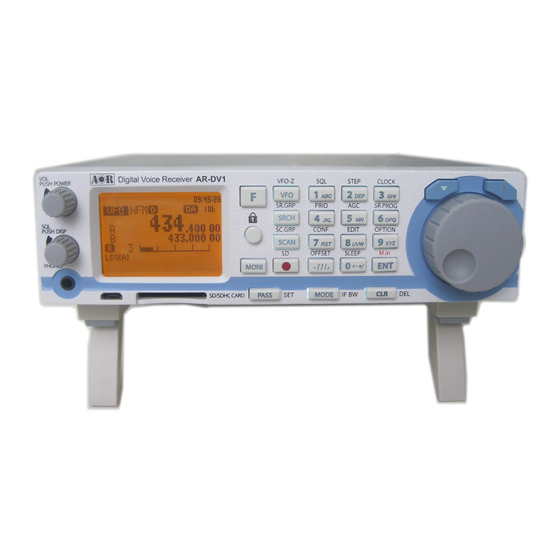
2 CONTROLS AND FUNCTIONS 2-1 FRONT PANEL VOL/POWER KNOB When power is connected to the receiver, the backlit LCD display changes to show the clock function on the screen. (Fig. 1-A) Fig. 1-A (Standby) Fig. 1-B Power on Fig. 1-C Power off To turn on the receiver, push the volume knob. - Page 11 SQL/DISP KNOB Rotate this knob to adjust the desired squelch level. Rotate clockwise until background noise goes off. The squelch level will be displayed on the screen according to the rotation of the squelch knob. When the knob is pressed, current squelch level will be displayed for 2 seconds. Push this knob for two seconds to view the squelch select menu, which will appear on the lower left of the display.
- Page 12 8 VFO VFO mode (VFO search, Program search, Memory read, Memory scan) 9 FM xx Receive mode: FM AM SAH SAL USB LSB CW xx: IF BW (bandwidth) FM: 200 100 30 15 6 (kHz) AM: 15 8 5.5 3.8 (kHz) SAH, SAL: 5.5 3.8 (kHz) USB,LSB : 2.6 1.8 (kHz) CW: 500 200 (Hz)
- Page 13 VI (Voice inversion) --- not available for USA consumer version In AM, SAH, SAL, USB, LSB, CW modes AGCF --- AGC speed fast AGCM --- AGC speed medium AGCS --- AGC speed slow In auto mode, LSQ is selected for all AM modes and NSQ is selected for all FM modes. RF-G ---- Receiver’s manual gain control by the squelch knob.
- Page 14 LOCK Press and hold this key for two seconds to activate the key lock function. While activated, all front panel keys are disabled to prevent accidental misoperation of the receiver. However, volume and squelch controls remain operative. To cancel, press and hold this key again for two seconds.
- Page 15 [CLR] This key is used to cancel frequency entry during programming or exit from a menu. ▼ ▼ ▼ ▼ In VFO search mode or program search mode, pressing this key will change frequency upward or change search direction. In memory mode, pressing this key will move to next channel. In memory scan mode, pressing this key will change the scan direction or resume scan.
-
Page 16: Rear Panel
2-2 REAR PANEL 1. Antenna input This input can be used to connect either the supplied telescopic antenna or an external antenna. When an external antenna is used, select one with 50 Ohms of impedance, unbalanced. 2. AUX output 3.5mm mono jack. The discriminator output (in FM mode only, 6kHz and 15kHz bandwidth) is 600 Ohm nominal, -20dBm output. -
Page 17: Getting Started
AR-DV1.) 3-2 SWITCHING ON FOR THE FIRST TIME Press the volume knob on the front panel of the AR-DV1. This is the power switch. As you push the volume knob, a ‘click’ will be heard. Please be careful NOT to switch on the receiver with an earphone connected because there may be an... -
Page 18: Volume Control
It will take approximately eight seconds before the main screen appears. This is a normal process to initialize the AR-DV1. To power off the AR-DV1, push and hold the power switch on the front panel for about two seconds. After the “AR-DV1 SHUTDOWN” message is displayed, the receiver will automatically power off. -
Page 19: Squelch Control
While squelch opens, “B” (busy) will appear in reverse contrast on the middle left of the LCD. 3-5 VFO SELECTION The AR-DV1 has three (3) VFOs identified as “VFO-A”, “VFO-B” and “VFO-Z” on the middle left of the LCD. The term VFO means ‘Variable Frequency Oscillator’, which today refers to a tunable data storage which contains frequency, step, step-adjust, attenuator etc. -
Page 20: Tuning Frequency
3-5-1 TUNING FREQUENCY 3-5-1-1 ENTERING A FREQUENCY USING THE NUMERIC KEYPAD While in VFO mode, enter the required frequency using MHz format followed by the [ENT] key. (Example) Frequency entry of 81.3 MHz Press the [8] key. Press the [1] key. Press the [.] key. Press the [3] key. Press the [ENT] key. (Example) Frequency entry of 1.134 MHz (1134 kHz) Press the [1] key. -
Page 21: Receive Mode
(While receiving frequency on VFO-Z, copy it to VFO-B) To confirm selection, press the [ENT] key. 3-6 RECEIVE MODE Due to the necessities of signal bandwidth, channel occupancy, and transmission efficiency, different receive modes are used by various services. The tuning step and receive mode are allocated by departments of governments following international discussions so they are not consistent throughout the world. -
Page 22: Digital Auto Mode
WFM – Wide Band Frequency Modulation Used by VHF and UHF broadcast stations because of its excellent audio quality, this is available due to the relatively wide frequency bandwidth employed. Used only for local services such as VHF band stereo channels. LSB –... -
Page 23: Receive Mode Selection
Alternatively, just long press the [MODE] key. AUTO MODE Note: Auto-mode is cancelled as soon as the receive mode is changed. 3-6-2 RECEIVE MODE SELECTION Any receive mode may be selected at any frequency within the receiver’s frequency coverage. To access the receive mode menu, press the [MODE] key. The following modes are available: AUTO, FM, AM, SAH, SAL, USB, LSB, CW, DSTR, YAES, DMR, D-CR, dPMR, P-25, ALINC. -
Page 24: Changing The Frequency Step
3-7 CHANGING THE FREQUENCY STEP The specification for channel occupancy, step (separation) and mode are decided by and allocated by the Departments of Governments following international discussions. The allocation of frequency bands are not the same all over the world and channel separation (step) varies from band to band. -
Page 25: Manually Selecting If Bandwidth
3 kHz – Short wave amateur band, short wave utility such as oceanic airband etc. 500 Hz – Morse code used by radio amateurs and some marine traffic on short wave An appropriate IF filter is automatically selected when auto mode is selected. However any combination of IF filter and receive mode is possible in the manual mode. -
Page 26: Additional Settings
When AGC is set to RF-G, the RF gain control can be adjusted by the squelch knob. 4-2 ATTENUATOR The attenuator reduces signal to the RF input stages of the AR-DV1. This helps prevent overloading due to connection to an external antenna or when the receiver is used close to strong transmissions. -
Page 27: Rf Gain
4-3 RF GAIN To activate the manual RF gain control, press the [F] key and then the [5] key. Rotate the dial knob to select “RF-G”. To change the RF gain manually, rotate the squelch knob. To cancel the manual RF gain control, repeat the steps above. -
Page 28: Vfo Setting
Following screen will appear. 4-5-1 VFO SEARCH DELAY The delay parameter affects the time the AR-DV1 will remain on an active frequency in VFO search mode once the received signal has disappeared and the squelch is closed. This is particularly useful for customizing how long the receiver will wait for a reply before continuing to search. -
Page 29: Del.bk39
To set the parameter, perform the following steps: 1. In the VFO search screen, use the [▼] key or [▲] key to select [STORE]. 2. Rotate the dial knob to select parameter ON or OFF. 3. To confirm entry, press the [ENT] key. To set other parameters, press the [▼] key. 4-5-4 DEL.BK39 This menu is to select ON or OFF to delete all data on memory bank 39 in VFO search mode. - Page 30 3. Rotate the dial knob to select set voice squelch function OFF or ON. (Default: OFF) 4. To select OFF, press the [ENT] key. It will return to normal display. 5. If ON is selected, press the [▼] key to select “DELAY” parameter in reverse contrast. 6.
-
Page 31: Managing A Sd Card
5 MANAGING A SD CARD The AR-DV1 has a built-in SD memory card interface used for voice recording and/or memory management. To access the menu to manage the SD card, perform the following steps: 1. Insert a SD memory card with a printed label facing upward into the slot on the front panel until you hear a click. -
Page 32: Backup Data To A Sd Card
To exit the SD card configuration menu, press the [CLR] key. 5-2 BACKUP DATA TO A SD CARD To backup memory channel, search bank contents, or receiver’s configuration data of the AR-DV1 to a SD card, perform the following steps: 1. -
Page 33: Restore Data From A Sd Card
5-3 RESTORE DATA FROM A SD CARD 1. Insert a new SD memory card with a printed label facing upward into the slot on the front panel until you hear a click. 2. Wait until “ ” icon appears on the right middle of the LCD. 3. -
Page 34: Recording Audio
5-5 PLAYBACK AUDIO FROM A SD CARD To playback recorded audio of the AR-DV1 on the SD memory card, perform the following steps: 1. Insert a SD memory card with a printed label facing upward into the slot on the front panel until you hear a click. - Page 35 While reading from the SD card, the following screen will appear. The file list of the SD card will appear. (1) Firmware file (2) Recorded files (3) Search bank data (4) Scan group data 5. Using the [ 5. or [▼] key, select the recorded file (in wav format). 6.
-
Page 36: Memory Channels And Banks
(memory channel) and each page may be overwritten with new data, so they can be used over and over again. The AR-DV1 has 2,000 memory channels and one priority channel. Each memory channel may hold:... - Page 37 If a mistake is made during programming, press the [CLR] key to abort entry and return to VFO mode. 1. Start by selecting VFO mode, then enter the frequency of 123.500 MHz. a) Press the [VFO] key to set the AR-DV1 into the VFO mode. b) Press the [1] key.
-
Page 38: Memory Read
Once frequency and mode data have been stored into a memory location, retrieval is quick and simple. While in VFO mode, press the [SCAN] key. There are 40 banks (#00 ~ 39), 50 channels per bank with the AR-DV1. (Sample of memory read screen) 1. -
Page 39: Scan - Scanning Memory Channels
7 SCAN – SCANNING MEMORY CHANNELS The AR-DV1 has a scan mode whereby the contents stored in the memory channels are automatically recalled and monitored very quickly for activity – scanned. (Note: It is important that you do not confuse SCAN and SEARCH modes.) SEARCH mode (covered later in this manual) automatically tunes the receiver through all frequencies between two specified frequency limits looking for active frequencies. -
Page 40: Scan Group
3. Press the [ENT] key to complete setting or press the [CLR] key to abort entry. 7-5-2 SCAN DELAY The scan delay parameter affects the time the AR-DV1 will remain on an active channel in the scan mode once the received signal has disappeared and the squelch is closed. This is particularly useful... -
Page 41: Scan Pause
for customizing how long the receiver will wait for a reply before continuing to scan. The parameter ranges are off, hold and 0.1 to 9.9 seconds in 0.1 second increments. (Default: 2.0 seconds) To set the scan delay parameter, perform the following steps: 1. -
Page 42: Search Mode
The VFO search is the easiest way of searching without programming. When the VFO-A is selected as a primary VFO, the AR-DV1 will search between two frequencies on VFO-A and VFO-B with receive mode, frequency step set in the VFO-A. -
Page 43: Program Search
This is useful to enable you to search back over an interesting point of the search process. 8-1-2-3 FORCING THE SEARCH TO RESUME If the AR-DV1 stops on an unwanted busy frequency, rotate the dial knob or press the [▼] key or [▲] key to force the search process to resume from the current frequency displayed. - Page 44 Up to 30 pass frequencies can be registered for each search bank. A total of 1200 pass frequencies can be registered in the AR-DV1. It is important to understand the pass function before taking action or transmissions may be missed.
-
Page 45: Search Group
After deleting the search bank, it will return to VFO-A mode. 8-2 SEARCH GROUP The AR-DV1 has 20 search groups to be used with the bank link function and other functions. The following parameters can be registered for each of the search groups. -
Page 46: Bank Link Setting
3. Press the [ENT] key to complete setting or press the [CLR] key to abort entry. 8-2-2 SEARCH DELAY The search delay parameter affects the time the AR-DV1 will remain on an active channel in the search mode once the received signal has disappeared and the squelch is closed. This is particularly useful for customizing how long the receiver will wait for a reply before continuing to search. -
Page 47: Configuration Menu
9 CONFIGURATION MENU The configuration menu is used to set fundamental operating parameters and other variables which do not appear in any menu heading. To access the configuration menu, press the [F] key and then the [7] key. CONFIGURATION MENU 1/4 BEEP Confirmation tone CONTRAST... -
Page 48: Configure Beep
Or, press the [▼] key to move to the next item on the configuration menu. 9-2 CONFIGURE CONTRAST The AR-DV1 is equipped with variable LCD contrast which is adjustable in 64 steps to provide the best visibility under different viewing angles. The default setting for contrast is 25. -
Page 49: Configure Dimmer
Or press the [▼] key to move to the next item on the configuration menu. 9-4 CONFIGURE DIMMER The AR-DV1 is equipped with high intensity LEDs to illuminate the LCD when operating in areas of low level lighting. The dimmer function adjusts the brightness of the backlit lamp and may be configured in two ways: This is default setting. -
Page 50: Configure Sql.skip
9-6 CONFIGURE SQL.SKIP The squelch skip menu is used to configure the SD card voice recording when squelch is open or closed. When squelch skip is set to OFF, the recording process will take place even when the squelch is closed and no audio signal is present. -
Page 51: Configure Res.code (Result Code)
Press the [▼] key to select “REMOTE.BPS” parameter in reverse contrast. Rotate the dial knob to select the desired baud rate from 9600, 19200, 38400, 57600, 115200 bps. The default setting is 115200 bps. Press the [ENT] key to accept the entry and return to a standard display. Alternatively, press the [CLR] key to abort entry. -
Page 52: Configure Firm Ver (Firmware Version)
To update the firmware, perform the following steps: 1. Insert the SD card with the new firmware file into the card slot on the front panel of the AR-DV1 receiver. 2. Press the [F] key and then the [7] key. -
Page 53: Option Menu
LCD. 10-5 CTCSS (CONTINUOUS TONE CONTROLLED SQUELCH SYSTEM) CTCSS function will enable the AR-DV1 to selectively receive only specifically modulated sub-audible tones or to verify the CTCSS frequency used. (Note: This function operates only in FM mode with less than 30 kHz of IF-BW.) To activate the function, perform the following steps: 1. -
Page 54: Dcs (Digital Coded Squelch)
2. Press the [▼] key to select “SQL” parameter in reverse contrast. 3. Rotate the dial knob to select “CTC” in reverse contrast. 4. Press the [▼] key to select “CTCSS” parameter in reverse contrast. 5. Rotate the dial knob to select the desired CTCSS tone frequency from the range of 60 Hz ~ 254.1 Hz as shown on the list below. -
Page 55: Scr (Analog Voice Descrambler)
DCS codes Default:017 10-7 SCR (ANALOG VOICE DESCRAMBLER) (Not available for US consumer version) Analog voice descrambler is used to decode scrambled analog voice transmission by frequency inversion. (Note: This function operates only in FM mode with less than 30 kHz of IF-BW.) To activate the function, perform the following steps: 1. -
Page 56: Miscellaneous Functions
11 MISCELLANEOUS FUNCTIONS 11-1 FREQUENCY STEP AND STEP ADJUST 11-1-1 FREQUENCY STEP To select frequency step, perform the following steps. 1. Press the [F] key and then the [2] key. 2. Rotate the dial knob to select one of the following preset frequency steps: 0.01kHz (10Hz), 0.05kHz (50Hz), 0.1kHz (100Hz), 0.5kHz (500Hz), 1kHz, 2kHz, 5kHz, 6.25kHz, 7.5kHz, 8.33kHz, 9kHz, 10kHz, 12.5kHz, 15kHz, 20kHz, 25kHz, 30kHz, 50kHz, 100kHz, 500kHz. -
Page 57: Dial Knob Setting
11-3 CLOCK / TIMER The AR-DV1 is equipped with a real time clock capable of 24 H format displaying hours, minutes, and seconds. (Caution: To use the clock function, power MUST be connected all the time. Disconnecting power will... -
Page 58: Alarm / Timer Configuration
3. Following screen will appear. 4. Press the [▼] key to select “NUMBER” in reverse contrast. 5. The AR-DV1 is equipped with three independent alarm/timer functions. Rotate the dial knob to select the number (from 1 ~ 3) to set ALARM/TIMER. - Page 59 4. Press the [ENT] key to confirm entry. Alternatively, press the [CLR] key to abort entry. “WEEKLY” events: The alarm function will operate repeatedly on selected day of the week. 1. Using the numeric keypad, enter the start time in MM-DD HH:MM format. 2.
-
Page 60: Alarm Activation
Once the alarm has been activated, “A” in reverse contrast will blink on the top middle of the LCD. The AR-DV1 will switch on automatically (presuming the receiver had been switched off) on a daily basis or weekly basis at the defined volume level and for the programmed length of time before automatically switching off again until the same time on the following day. -
Page 61: Sleep Timer
If no SD card is inserted into slot, an error message will appear. 11-3-5 SLEEP TIMER Once the sleep timer is activated, the AR-DV1 will automatically switch off after the sleep time duration has expired. To set sleep timer, perform the following steps: 1. -
Page 62: Priority Function
The priority checking is accomplished by momentarily tuning the receive circuit to the priority frequency to see if it is active. If activity is found, the AR-DV1 will remain on the active frequency until the signal disappears. If no activity is detected, the receiver returns to the VFO frequency, scan channel or search bank from where it originated. -
Page 63: Reset The Ar-Dv1
11-5 RESET THE AR-DV1 Resetting the AR-DV1 will return it to the original factory default settings and all memory contents will be deleted. There are two types of resetting; System Reset and Full Reset. 11-5-1 SYSTEM RESET Performing System Reset will return it to the original factory default settings. -
Page 64: Last Channel Memory
6. To confirm entry, press the [ENT] key. Alternatively, press the [CLR] key to cancel entry. 11-7 LAST CHANNEL MEMORY When the AR-DV1 is switched off, the receiver’s settings will be automatically saved on the last channel memory and will be recalled the next time the unit is switched on. -
Page 65: Data Entry
11-8 DATA ENTRY Data entry can be made by the numeric keypad. Following characters are available for data entry: A ~ Z, 0 ~ 9, [, ], _, |, ,, . , +, -, *, /, [SPACE] Below characters/numbers are assigned to respective keypad: 1 ->... -
Page 66: Data Editor
11-9 DATA EDITOR Data Editor function is used to copy or move the information in the search banks, memory banks or memory channels. To access the data editor function, perform the following steps: 1. Press the [F] key and then the [8] key. 2. -
Page 67: Specifications
SPECIFICATIONS Frequency range: 100 kHz ~ 1300* MHz (Note: Specifications guaranteed above 530 kHz) (Cellular frequencies blocked for US consumer version) Digital receive modes: D-STAR (GMSK), ALINCO (GMSK), YAESU (C4FM), DIGITAL CR (C4FM), NXDN (C4FM), dPMR (C4FM), P25 (Phase 1) (C4FM), DMR (4FSK). - Page 68 ** Digital voice mode compatibility chart: AR-DV1 VOICE DIGITAL MODE BANDWIDTH MODE VARIOUS COMPATIBLE VOCODER DECODING D-STAR 12.5kHz AMBE 12.5kHz AMBE ALINCO DIGITAL EJ-47 (voice mode F1E) 12.5kHz V/D mode AMBE+2 YAESU DIGITAL 12.5kHz Voice FR mode 6.25kHz NON-ENCRYPTED AMBE+2 DIGITAL CR 6.25kHz...
-
Page 69: Limited Warranty (Usa Only)
AOR USA, Inc. (AOR) warrants its receivers as described below: AOR will repair or exchange equipment as a result of defects in parts or workmanship for a period of one year from the date of original retail purchase from an authorized AOR dealer. - Page 70 If you have questions about this limited warranty, or the operation of your AOR product, contact AOR at (310) 787-8615 during normal business hours (9 am ~ 5 pm Pacific Time Zone), or write to AOR, 20655 S. Western Ave., Suite 112, Torrance, CA 90501. You may also send a fax to AOR at (310) 787-8619.
- Page 72 Manufacturer: AOR, LTD. 2-6-4, Misuji, Taito-Ku, Tokyo, 111-0055, Japan URL: www.aorja.com US distributor: AOR USA, INC. 20655 S. Western Ave. Suite 112 Torrance, CA 90501 Phone: 310-787-8615 Fax: 310-787-8619 URL: www.aorusa.com e-mail: info@aorusa.com August 20, 2015 Printed in Japan...
Need help?
Do you have a question about the AR-DV1 and is the answer not in the manual?
Questions and answers