Linksys SRW2016 User Manual
Business series webview switch
Hide thumbs
Also See for SRW2016:
- User manual (123 pages) ,
- Specifications (3 pages) ,
- User manual (73 pages)
Table of Contents
Advertisement
Advertisement
Table of Contents

Related Manuals for Linksys SRW2016


Summary of Contents for Linksys SRW2016
- Page 1 SRW2008/SRW2008P/SRW2008MP...
-
Page 2: Copyright And Trademarks
WebView Switches Copyright and Trademarks Specifications are subject to change without notice. Linksys is a registered trademark or trademark of Cisco Systems, Inc. and/or its affiliates in the U.S. and certain other countries. Copyright © 2006 Cisco Systems, Inc. All rights reserved. -
Page 3: Table Of Contents
Connecting the Switch Chapter 4: Using the Console Interface for Configuration Overview Configuring the HyperTerminal Application Connecting to the Switch through a Telnet Session Configuring the Switch through the Console Interface Chapter 5: Using the Web-based Utility for Configuration Overview... - Page 4 WebView Switches VLAN Management Tab - GVRP Statistics Tab - RMON Statistics Statistics Tab - RMON History Statistics Tab - RMON Alarm Statistics Tab - RMON Events Statistics Tab - Port Utilization Statistics Tab - 802.1x Statistics Statistics Tab - GVRP Statistics ACL Tab - IP Based ACL ACL Tab - MAC Based ACL Security Tab - ACL Binding...
- Page 5 Appendix A: About Gigabit Ethernet and Fiber Optic Cabling Gigabit Ethernet Fiber Optic Cabling Appendix B: Windows Help Appendix C: Downloading using Xmodem Startup Menu Procedures Appendix D: Glossary Appendix E: Specifications SRW2048 SRW2016/SRW2024 SRW224G4/SRW248G4 Appendix F: Warranty Information Appendix G: Regulatory Information Appendix H: Contact Information...
-
Page 6: List Of Figures
Figure 2-2: Back Panel of the SRW2048 Figure 2-3: Front Panel of the SRW2024 Figure 2-4: Back Panel of the SRW2024 Figure 2-5: Front Panel of the SRW2016 Figure 2-6: Back Panel of the SRW2016 Figure 2-7: Front Panel of the SRW248G4... - Page 7 WebView Switches Figure 4-16: SSH Status Figure 4-17: SSH Crypto Key Generation Figure 4-18: SSH Keys Fingerprints Figure 4-19: Username & Password Settings Figure 4-20: Security Settings Figure 4-21: SSL Certificate Generation Figure 4-22: SSL Certificate Figure 4-23: IP Configuration Figure 4-24: IP Address Configuration Figure 4-25: HTTP Figure 4-26: HTTPS Configuration...
- Page 8 WebView Switches Figure 5-12: VLAN Management - Ports to VLAN Figure 5-13: VLAN Management - VLAN to Ports Figure 5-14: VLAN to Ports - Join VLAN Figure 5-15: VLAN Management - GVRP Figure 5-16: Statistics - RMON Statistics Figure 5-17: Statistics - RMON History Figure 5-18: RMON History Table Figure 5-19: Statistics - RMON Alarm Figure 5-20: Statistics - RMON Events...
- Page 9 WebView Switches Figure 5-42: Advanced Mode - Policy Name Figure 5-43: Advanced Mode - New Class Map Figure 5-44: Advanced Mode - New Aggregate Policer Figure 5-45: Spanning Tree - STP Status Figure 5-46: Spanning Tree - Global STP Figure 5-47: Spanning Tree - STP Port Settings Figure 5-48: Spanning Tree - RSTP Port Settings Figure 5-49: Spanning Tree - MSTP Properties Figure 5-50: Spanning Tree - MSTP Instance Settings...
- Page 10 WebView Switches Figure 5-73: Admin - Server Logs Figure 5-74: Admin - Memory Logs Figure 5-75: Admin - Flash Logs Figure C-1: Auto-Boot Message Figure C-2: Startup Menu Figure C-3: Send File Figure C-4: Download...
-
Page 11: Chapter 1: Introduction Welcome
If a specific model number is mentioned, then the feature is specific to that model. The Linksys WebView Managed Switch allows you to expand your network securely. Configuration of the switch is secured using SSL for Web access. User control is secured using 802.1x security using a RADIUS authentication mechanism and can also be controlled using MAC-based filtering. - Page 12 WebView Switches There are features that allow you to expand and grow your network of switches. Link aggregation allows multiple high-bandwidth trunks between switches to be setup. This also provides a level of reliability in that the system continues to operate if one of the links break. Spanning Tree (STP), Fast Linkover, Rapid Spanning Tree (RSTP) and Multiple Spanning Tree (MSTP) allows you to build a mesh of switches increasing the availability of the system.
-
Page 13: What's In This User Guide
This appendix supplies the Switch’s warranty information. • Appendix G: Regulatory Information This appendix supplies the Switch’s regulatory information. • Appendix H: Contact Information This appendix provides contact information for a variety of Linksys resources, including Technical Support. Chapter 1: Introduction What’s in this User Guide? -
Page 14: Chapter 2: Getting To Know The Switch
Switch is actively sending or receiving data over that port. Orange. The LED lights up orange to indicate a 1000Mbps connection on the corresponding port (1 through 48) with an attached device. It flashes to indicate that the Switch is actively sending or receiving data over that port. -
Page 15: Figure 2-2: Back Panel Of The Srw2048
1000Mbps. Use the Linksys MGBT1, MGBSX1, or MGBLH1 miniGBIC modules with the Switch. The MGBSX1 and the MGBLH1 require fiber cabling with LC connectors, while the MGBT1 requires a Category 5e Ethernet cable with an RJ-45 connector. -
Page 16: Srw2024
Figure 2-3: Front Panel of the SRW2024 LEDs SYSTEM Green. The SYSTEM LED lights up to indicate that the Switch is powered on. Link/Act (1-24) Green. The LED lights up green to indicate a functional 10/100Mbps network link through the corresponding port (1 through 24) with an attached device. It flashes to indicate that the Switch is actively sending or receiving data over that port. -
Page 17: Figure 2-4: Back Panel Of The Srw2024
1000Mbps. Use the Linksys MGBT1, MGBSX1, or MGBLH1 miniGBIC modules with the Switch. The MGBSX1 and the MGBLH1 require fiber cabling with LC connectors, while the MGBT1 requires a Category 5e Ethernet cable with an RJ-45 connector. -
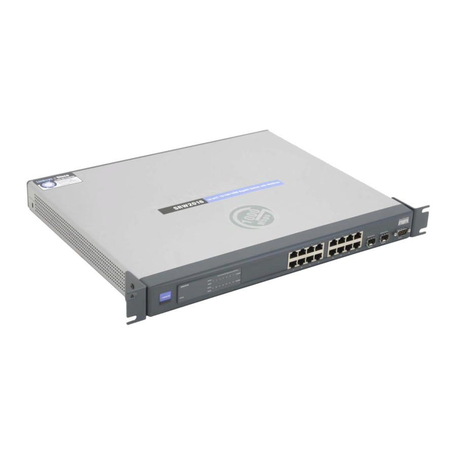
Page 18: Srw2016
Figure 2-5: Front Panel of the SRW2016 LEDs SYSTEM Green. The SYSTEM LED lights up to indicate that the Switch is powered on. Link/Act (1-16) Green. The LED lights up green to indicate a functional 10/100Mbps network link through the corresponding port (1 through 16) with an attached device. It flashes to indicate that the Switch is actively sending or receiving data over that port. -
Page 19: The Back Panel
1000Mbps. Use the Linksys MGBT1, MGBSX1, or MGBLH1 miniGBIC modules with the Switch. The MGBSX1 and the MGBLH1 require fiber cabling with LC connectors, while the MGBT1 requires a Category 5e Ethernet cable with an RJ-45 connector. -
Page 20: Srw248G4
Switch is actively sending or receiving data over that port. Orange. The LED lights up orange to indicate a 1000Mbps connection on the corresponding port (G1 through G4) with an attached device. It flashes to indicate that the Switch is actively sending or receiving data over that port. -
Page 21: Figure 2-8: Back Panel Of The Srw248G4
1000Mbps. Use the Linksys MGBT1, MGBSX1, or MGBLH1 miniGBIC modules with the Switch. The MGBSX1 and the MGBLH1 require fiber cabling with LC connectors, while the MGBT1 requires a Category 5e Ethernet cable with an RJ-45 connector. -
Page 22: Srw224G4
The Switch's LEDs and ports are located on the front panel. Figure 2-9: Front Panel of the SRW224G4 LEDs Green. The PWR LED lights up to indicate that the Switch is powered on. Link/Act (1-24) Green. The LED lights up green to indicate a functional 10/100Mbps network link through the corresponding port (1 through 16) with an attached device. -
Page 23: Figure 2-10: Back Panel Of The Srw224G4
1000Mbps. Use the Linksys MGBT1, MGBSX1, or MGBLH1 miniGBIC modules with the Switch. The MGBSX1 and the MGBLH1 require fiber cabling with LC connectors, while the MGBT1 requires a Category 5e Ethernet cable with an RJ-45 connector. -
Page 24: Chapter 3: Connecting The Switch
WebView Switches Chapter 3: Connecting the Switch Overview This chapter will explain how to connect network devices to the Switch. For an example of a typical network configuration, see the application diagram shown below. Cable/DSL Wireless Modem Internet Router Access Point... -
Page 25: Maximum Distance
• Keep cabling away from sources of electrical noise, power lines, and fluorescent lighting fixtures. • Position the Switch away from water and moisture sources. • To ensure adequate air flow around the Switch, be sure to provide a minimum clearance of two inches (50 mm). -
Page 26: Placement Options
Placement Options Before connecting cables to the Switch, first you will physically install the Switch. Either set the Switch on its four rubber feet for desktop placement or mount the Switch in a standard-sized, 19-inch wide, 1U high rack for rack- mount placement. -
Page 27: Connecting The Switch
(This PC must be running the VT100 terminal emulation software, such as HyperTerminal.) 7. Connect the supplied power cord to the Switch’s power port, and plug the other end into an electrical outlet. IMPORTANT: Make sure you use the power cord that is supplied with the Switch. Use of a different power cord could damage the Switch. -
Page 28: Chapter 4: Using The Console Interface For Configuration
SRW2048. Select an icon for the application. Then, click the OK button. 3. On the Connect To screen, select a port to communicate with the Switch: COM1, COM2, or TCP/IP. Chapter 4: Using the Console Interface for Configuration... -
Page 29: Connecting To The Switch Through A Telnet Session
Flow control: None Then, click the OK button. Connecting to the Switch through a Telnet Session Open a command line editor and enter telnet 192.168.1.254. Then, press the Enter key. The Login screen will now appear. The first time you open the CLI interface, select Edit and hit Enter. Enter admin in the User Name field. -
Page 30: Configuring The Switch Through The Console Interface
WebView Switches Configuring the Switch through the Console Interface The console screens consist of a series of menus. Each menu has several options, which are listed vertically. You select a menu option when you highlight it; pressing the Enter key activates the highlighted option. -
Page 31: Figure 4-7: System Configuration Menu
4. Security Settings Figure 4-7: System Configuration Menu 5. IP Configuration 6. File Management 7. Restore System Default Settings 8. Reboot System 0. Back to main menu Chapter 4: Using the Console Interface for Configuration Configuring the Switch through the Console Interface... -
Page 32: Figure 4-8: System Information Menu
WebView Switches System Information Using this screen, you can check the Switch’s firmware versions and general system information. Figure 4-8: System Information Menu Versions The Versions screen displays the Switch’s boot, software, and hardware firmware versions. Figure 4-9: Versions General System Information The General System Information screen displays the Switch’s description, System Up Time, System MAC... -
Page 33: Figure 4-11: Management Settings Menu
Figure 4-11: Management Settings Menu Serial Port Configuration On the Serial Port Configuration screen, the Switch’s baud rate is displayed. Select Edit and press the Enter key to make changes. Toggle to the desired speed and when your changes are complete, press the Esc key to return to the Action menu. -
Page 34: Figure 4-14: Ssh Configuration
The SSH Status screen displays whether the SSH Server is enabled, the RSA and DSA key status, and any open SSH sessions. Select Refresh to update the screen if necessary. To exit, select Quit and press the Enter key. Figure 4-16: SSH Status Chapter 4: Using the Console Interface for Configuration Configuring the Switch through the Console Interface... -
Page 35: Figure 4-17: Ssh Crypto Key Generation
On the SSH Keys Fingerprints screen, the RSA and DSA keys will be displayed if they have been generated. Select Refresh to update the screen if necessary. To exit, select Quit and press the Enter key. Figure 4-18: SSH Keys Fingerprints Chapter 4: Using the Console Interface for Configuration Configuring the Switch through the Console Interface... -
Page 36: Figure 4-19: Username & Password Settings
NOTE: The Username & Password Settings screen can also be used to set passwords for other users. Security Settings The Security Settings screen enables you to configure security settings on the Switch, as well as generate and display the certificate. SSL Certificate Generation Use the Certificate Generation screen to specify a device-generated certificate. -
Page 37: Figure 4-22: Ssl Certificate
NOTE: This setting has no effect when Management Access Rules are not defined. IP Configuration The IP Configuration screen displays these choices: the Switch’s IP Address Settings, HTTP, HTTPS Configuration and Network Configuration. Chapter 4: Using the Console Interface for Configuration... -
Page 38: Figure 4-24: Ip Address Configuration
Figure 4-24: IP Address Configuration DHCP client. The status of the DHCP client is displayed. If you want the Switch to be a DHCP client, then select ENABLE. If you want to assign an static IP address to the Switch, then enter the IP settings and select DISABLE. -
Page 39: Figure 4-27: Network Configuration
Action menu. Select Save and press the Enter key to save your changes. To exit, select Quit and press the Enter key. Figure 4-29: TraceRoute Test Chapter 4: Using the Console Interface for Configuration Configuring the Switch through the Console Interface... -
Page 40: Figure 4-30: File Management
Reboot System Select Reboot System and press the Enter key if you want to restart the Switch. You will be asked if you want to continue. Press the y key to reboot the Switch, or press the n key to cancel. After the Switch has rebooted, the Switch Main Menu screen will appear. -
Page 41: Figure 4-33: Port Status
WebView Switches Port Status On the Switch Main Menu screen, select Port Status and press the Enter key if you want to view the status information for the Switch’s ports. The Port Status screen displays the port numbers, their status, Link status, speed and duplex mode, and status of flow control, which is the flow of packet transmissions. -
Page 42: Chapter 5: Using The Web-Based Utility For Configuration
WebView Switches. The screen images were taken from the SRW2048 Switch. Additional features for specific Switches are noted. Some functionality on the SRW224G4, SRW248G4, SRW2016 and SRW2024 Switches may not be fully functional but will be corrected with future firmware upgrades. -
Page 43: Setup Tab - Summary
The Summary screen provides device and system information about the Switch. Device Information System Name. Displays the name for the Switch, if one has been entered on the Setup - Network Settings tab. IP Address.The IP address of the Switch is displayed here (configurable from Setup - Network Settings tab). -
Page 44: Setup Tab - Network Settings
System Name. This field allows you to assign a system name. System Location. This field is used for entering a description of where the Switch is located, such as 3rd floor. System Contact. Enter the administrative contact person in this field. -
Page 45: Setup Tab - Time
Daylight Saving. Select Daylight Saving to enable it on the Switch. If the Switch should use US daylight savings, then select USA. If the Switch should use EU daylight savings, then select European. If it should use another kind of daylight savings, then select Custom and complete the From and To fields. -
Page 46: Sntp Servers
Port Management Tab - Port Settings The Port Management - Port Settings screen shows you the settings for each of the Switch’s ports. Port. The number of the port. To use an SFP module, click on the Detail button of the appropriate port (G1, G2). -
Page 47: Figure 5-6: Port Settings - Port Configuration Detail
MDI/MIDX. This is the MDI/MDIX status of the port. The MDI setting is used if the port is connected to an end station. The MDIX setting is used if the port is connected to a hub or another switch. Flow Control. This is the flow control status of the port. It is active when the port uses Full Duplex Mode. - Page 48 MDI/MDIX. Select the Auto setting if you want the port to automatically detect the cable type. Select MDI if the port is connected to an end station. Select MDIX if the port is connected to a hub or another switch.
-
Page 49: Port Management Tab - Link Aggregation
WebView Switches Port Management Tab - Link Aggregation LAG. This indicates if the port is part of a LAG. Description. Description for this LAG. Admin Status. The admin status of the LAG. Up indicates that the LAG is available. Down indicates that administrator has taken the port offline. -
Page 50: Port Management Tab - Lacp
Figure 5-9: Port Management - LACP Admin Key. A channel will only be formed between ports having the same admin key. This only applies to ports located on the same switch. Chapter 5: Using the Web-based Utility for Configuration Port Management Tab - LACP... -
Page 51: Vlan Management Tab - Create Vlan
WebView Switches VLAN Management Tab - Create VLAN The Create VLAN screen provides information and global parameters for configuring and working with VLANs. Single VLAN VLAN ID (2-4094). Indicates the ID number of the VLAN being configured. Up to 256 VLANs can be created. This field is used to add VLANs one at a time. -
Page 52: Vlan Management Tab - Ports To Vlan
WebView Switches Acceptable Frame Type. Packet type accepted on the port. Possible values are: • Admit All. Indicates that both tagged and untagged packets are accepted on the port. • Admit Tag Only. Indicates that only tagged packets are accepted on the port. PVID. -
Page 53: Vlan Management Tab - Vlan To Ports
WebView Switches Exclude. Excludes the interface from the VLAN. However, the interface cannot be added to the VLAN through GVRP. VLAN Management Tab - VLAN to Ports The VLAN to Ports screen contains fields for configuring VLANs to a ports. Port. -
Page 54: Vlan Management Tab - Gvrp
WebView Switches VLAN Management Tab - GVRP GARP VLAN Registration Protocol (GVRP) is specifically provided for automatic distribution of VLAN membership information among VLAN-aware bridges. GVRP allows VLAN-aware bridges to automatically learn VLANs to bridge ports mapping, without having to individually configure each bridge and register VLAN membership. The Global System LAG information displays the same field information as the ports, but represents the LAG GVRP information. -
Page 55: Statistics Tab - Rmon Statistics
WebView Switches Statistics Tab - RMON Statistics The RMON Statistics screen contains fields for viewing information about device utilization and errors that occurred on the device. Interface. Indicates the device for which statistics are displayed. The possible field values are: •... -
Page 56: Statistics Tab - Rmon History
WebView Switches Oversize Packets. Displays the number of oversized packets (over 1518 octets) received on the interface since the device was last refreshed. Fragments. Displays the number of fragments (packets with less than 64 octets, excluding framing bits, but including FCS octets) received on the interface since the device was last refreshed. Jabbers. -
Page 57: Figure 5-18: Rmon History Table
WebView Switches Log Table Source Interface. Displays the interface from which the history samples were taken. Sampling Interval. Indicates the time in seconds that samplings are taken from the port. Sampling Requested. Displays the number of samples to be saved. The field range is 1-65535. The default value is 50. -
Page 58: Statistics Tab - Rmon Alarm
WebView Switches Undersize Packets. Displays the number of undersized packets (less than 64 octets) received on the interface since the device was last refreshed. Oversize Packets. Displays the number of oversized packets (over 1518 octets) received on the interface since the device was last refreshed. - Page 59 WebView Switches Rising Threshold. Displays the rising counter value that triggers the rising threshold alarm. The rising threshold is presented on top of the graph bars. Each monitored variable is designated a color. Rising Event. Displays the mechanism in which the alarms are reported. The possible field values are: •...
-
Page 60: Statistics Tab - Rmon Events
WebView Switches Statistics Tab - RMON Events The RMON Events screen contains fields for defining RMON events. Add Event Event Entry. Displays the event. Community. Displays the community to which the event belongs. Description. Displays the user-defined event description. Type. Describes the event type. Possible values are: •... -
Page 61: Statistics Tab - Port Utilization
WebView Switches Statistics Tab - Port Utilization The Port Utilization screen displays the amount of resources each interface is currently consuming. Ports in green are functioning normally, while ports in red are currently transmitting an excessive amount of network traffic. Refresh Rate. -
Page 62: Statistics Tab - Gvrp Statistics
WebView Switches Statistics Tab - GVRP Statistics The GVRP Statistics screen contains device statistics for GVRP. The GVRP Statistics screen is divided into two areas, GVRP Statistics Table and GVRP Error Statistics Table. The following fields are relevant for both tables: Interface. -
Page 63: Acl Tab - Ip Based Acl
WebView Switches Invalid Attribute Value. Displays the device GVRP Invalid Attribute Value statistics. Invalid Attribute Length. Displays the device GVRP Invalid Attribute Length statistics. Invalid Event. Displays the device GVRP Invalid Events statistics. The Clear All Counters button resets all tables. ACL Tab - IP Based ACL The IP Based ACL (Access Control List) screen contains information for defining IP Based ACLs. - Page 64 WebView Switches • TCP. Indicates that the Transmission Control Protocol is used to classify network flows. • OSPF. Matches the packet to the Open Shortest Path First (OSPF) protocol. • UDP. Indicates that the User Datagram Protocol is used to classify network flows. •...
-
Page 65: Acl Tab - Mac Based Acl
WebView Switches Wildcard Mask. Defines the source IP address wildcard mask. Wildcard masks specify which bits are used and which bits are ignored. A wild card mask of 255.255.255.255 indicates that no bit is important. A wildcard of 0.0.0.0 indicates that all the bits are important. For example, if the source IP address 149.36.184.198 and the wildcard mask is 255.36.184.00, the first eight bits of the IP address are ignored, while the last eight bits are used. -
Page 66: Security Tab - Acl Binding
WebView Switches Wildcard Mask. Defines the source IP address wildcard mask. Wildcard masks specify which bits are used and which bits are ignored. A wild card mask of 255.255.255.255 indicates that no bit is important. A wildcard of 0.0.0.0 indicates that all the bits are important. For example, if the source IP address 149.36.184.198 and the wildcard mask is 255.36.184.00, the first eight bits of the IP address are ignored, while the last eight bits are used. -
Page 67: Security Tab - Radius
WebView Switches Security Tab - RADIUS Remote Authorization Dial-In User Service (RADIUS) servers provide additional security for networks. RADIUS servers provide a centralized authentication method for web access. IP Address. The Authentication Server IP address. Priority. The server priority. The possible values are 0-65535, where 1 is the highest value. The RADIUS Server priority is used to configure the server query order. -
Page 68: Security Tab - Tacacs
WebView Switches Security Tab - TACACS+ The device provides Terminal Access Controller Access Control System (TACACS+) client support. TACACS+ provides centralized security for validation of users accessing the device. TACACS+ provides a centralized user management system, while still retaining consistency with RADIUS and other authentication processes. The TACACS+ protocol ensures network integrity through encrypted protocol exchanges between the device and TACACS+ server. -
Page 69: Security Tab - 802.1X Settings
Quiet Period. Specifies the number of seconds that the switch remains in the quiet state following a failed authentication exchange (Range: 0-65535). Resending EAP. Specifies the number of seconds that the switch waits for a response to an EAP - request/ identity frame, from the supplicant (client), before resending the request. -
Page 70: Security Tab - Port Security
WebView Switches Server Timeout. Specifies the number of seconds that lapses before the switch resends a request to the authentication server (Range: 1-65535). The field default is 30 seconds. Security Tab - Port Security Network security can be increased by limiting access on a specific port only to users with specific MAC addresses. -
Page 71: Security Tab - Multiple Hosts
WebView Switches In order to change the Learning Mode, the Lock Interface must be set to Unlocked. Once the mode is changed, the Lock Interface can be reinstated. Max Entries. Specifies the number of MAC addresses that can be learned on the port. The Max Entries field is enabled only if Locked is selected in the Interface Status field. -
Page 72: Security Tab - Storm Control
WebView Switches Trap Frequency. Defines the time period by which traps are sent to the host. The Trap Frequency (1-1000000) field can be defined only if multiple hosts are disabled. The default is 10 seconds. The table contains the following additional fields: Status. -
Page 73: Qos Tab - Cos Settings
• Advanced. Enables Advanced mode QoS on the interface. This feature has been added to version 1.2 of the SRW2024/SRW2016 and version 1.1 of the SRW224G4/SRW248G4. Class of Service. Specifies the CoS priority tag values, where zero is the lowest and 7 is the highest. -
Page 74: Cos Default
WebView Switches CoS Default Interface. Interface to which the CoS configuration applies. Default CoS. Determines the default CoS value for incoming packets for which a VLAN tag is not defined. The possible field values are 0-7. The default CoS is 0. Restore Defaults. -
Page 75: Qos Tab - Bandwidth
Service mode, as bandwidth settings are based on services. This feature has been added to version 1.2 of the SRW2024/SRW2016 and version 1.1 of the SRW224G4/SRW248G4. Queue shaping can be based per queue and/or per interface. Shaping is determined by the lower specified value. -
Page 76: Qos Tab - Advanced Mode
The rules are based on the Access Control Lists (see Access Control Tab). This feature has been added to version 1.2 of the SRW2024/SRW2016 and version 1.1 of the SRW224G4/SRW248G4. MAC ACLs and IP ACLs can be grouped together in more complex structures, called policies. Policies can be applied to an interface. -
Page 77: Figure 5-43: Advanced Mode - New Class Map
WebView Switches New Class Map screen Class Map Name. Defines a new Class Map name Preferred ACL. Indicates if packets are first matched to an IP based ACL or a MAC based ACL. The possible field values are: • IP Based ACLs. Matches packets to IP based ACLs first, then matches packets to MAC based ACLs. •... -
Page 78: Spanning Tree
WebView Switches Spanning Tree Spanning Tree Protocol (STP) provides tree topography for any arrangement of bridges. STP also provides one path between end stations on a network, eliminating loops. Loops occur when alternate routes exist between hosts. Loops in an extended network can cause bridges to forward traffic indefinitely, resulting in increased traffic and reducing network efficiency. -
Page 79: Spanning Tree Tab - Global Stp
WebView Switches Root Hello Time (sec). Indicates the device Hello Time. The Hello Time indicates the amount of time in seconds a root bridge waits between configuration messages. The default is 2 seconds. The range is 1 to 10 seconds. Root Forward delay (sec). -
Page 80: Bridge Settings
WebView Switches • Long. Specifies 1 through 200,000,000 range for port path costs.The default path costs assigned to an interface varies according to the selected method. Bridge Settings Priority. Specifies the bridge priority value. When switches or bridges are running STP, each is assigned a priority. - Page 81 WebView Switches • Blocking. Indicates that the port is currently blocked and cannot forward traffic or learn MAC addresses. Blocking is displayed when Classic STP is enabled. • Listening. Indicates that the port is in Listening mode. The port cannot forward traffic nor can it learn MAC addresses.
-
Page 82: Spanning Tree Tab - Rstp Port Settings
• Root. Provides the lowest cost path to forward packets to root switch. • Designated. Indicates that the port or LAG via which the designated switch is attached to the LAN. • Alternate. Provides an alternate path to the root switch from the root interface. -
Page 83: Spanning Tree Tab - Mstp Properties
The link remains configured for communications until explicit LCP or NCP packets close the link, or until some external event occurs. This is the actual switch port link type. It may differ from the administrative state. • Disabled. Disables point-to-point link. -
Page 84: Spanning Tree Tab - Mstp Instance Settings
WebView Switches Spanning Tree Tab - MSTP Instance Settings MSTP operation maps VLANs into STP instances. Packets assigned to various VLANs are transmitted along different paths within Multiple Spanning Trees Regions (MST Regions). Regions are one or more Multiple Spanning Tree bridges by which frames can be transmitted. In configuring MST, the MST region to which the device belongs is defined. - Page 85 WebView Switches • Boundary Port. Indicates the port is a boundary port. A Boundary port attaches MST bridges to LAN in an outlying region. If the port is a boundary port, it also indicates whether the device on the other side of the link is working in RSTP or STP mode.
-
Page 86: Multicast Tab - Igmp Snooping
Leave Timeout. Indicates the amount of time the host waits, after requesting to leave the IGMP group and not receiving a Join message from another station, before timing out. If a Leave Timeout occurs, the switch notifies the Multicast device to stop sending traffic The Leave Timeout value is either user-defined, or an immediate leave value. -
Page 87: Multicast Tab - Bridge Multicast
WebView Switches Multicast Tab - Bridge Multicast The Bridge Multicast screen displays the ports and LAGs attached to the Multicast service group in the Ports and LAGs tables. The Port and LAG tables also reflect the manner in which the port or LAGs joined the Multicast group. Ports can be added either to existing groups or to new Multicast service groups. -
Page 88: Multicast Tab - Bridge Multicast Forward All
Multicast Tab - Bridge Multicast Forward All The Bridge Multicast Forward All screen contains fields for attaching ports or LAGs to a device that is attached to a neighboring Multicast router/switch. Once IGMP Snooping is enabled, Multicast packets are forwarded to the appropriate port or VLAN. -
Page 89: Snmp Tab - Views
WebView Switches SNMP Notifications. Indicates if the device can send SNMP notifications. Authentication Notifications. Indicates if SNMP Authentication failure notification is enabled on the device. SNMP Tab - Views SNMP Views provide access or block access to device features or feature aspects. For example, a view can be defined that states that SNMP Group A has Read Only (R/O) access to Multicast groups, while SNMP Group B has Read-Write (R/W) access to Multicast groups. -
Page 90: Snmp Tab - Group Profile
WebView Switches SNMP Tab - Group Profile The Group Profile screen provides information for creating SNMP groups and assigning SNMP access control privileges to SNMP groups. Groups allow network managers to assign access rights to specific device features, or features aspects. Group Name. -
Page 91: Snmp Tab - Group Membership
WebView Switches SNMP Tab - Group Membership The Group Membership screen provides information for assigning SNMP access control privileges to SNMP groups. User name. Provides a user-defined local user list. Engine ID. Indicates either the local or remote SNMP entity to which the user is connected. Changing or removing the local SNMP Engine ID deletes the SNMPv3 User Database. -
Page 92: Snmp Tab - Communities
WebView Switches The Add to List button adds the Group Membership configuration to the respective table at the bottom of the screen. SNMP Tab - Communities The Communities screen contains three areas, Communities, Basic Table and Advanced Table. SNMP Management Station. Defines the management station IP address for which the advanced SNMP community is defined. -
Page 93: Advanced Table
WebView Switches Community String. Displays the password used to authenticate the management station to the device. Access Mode. Displays the access rights of the community. View Name. Displays the user-defined SNMP view. Advanced Table Management Station. Displays the management station IP address for which the basic SNMP community is defined. -
Page 94: Snmp Tab - Notification Recipient
WebView Switches SNMP Tab - Notification Recipient The Notification Recipient screen contains information for defining filters that determine whether traps are sent to specific users, and the trap type sent. SNMP notification filters provide the following services: • Identifying Management Trap Targets •... -
Page 95: Admin Tab - User Authentication
WebView Switches • Authentication. Indicates the packet is authenticated. • Privacy. Indicates the packet is both authenticated and encrypted. UDP Port. Displays the UDP port used to send notifications. The default is 162. Filter Name. Indicates if the SNMP filter for which the SNMP Notification filter is defined. Timeout. -
Page 96: Admin Tab - Jumbo Frames
Admin Tab - Static Address A static address can be assigned to a specific interface on this switch. Static addresses are bound to the assigned interface and cannot be moved. When a static address is seen on another interface, the address will be ignored and will not be written to the address table. -
Page 97: Admin Tab - Dynamic Address
The Dynamic Address Table contains the MAC addresses learned by monitoring the source address for traffic entering the switch. When the destination address for inbound traffic is found in the database, the packets intended for that address are forwarded directly to the associated port. Otherwise, the traffic is flooded to all ports. -
Page 98: Admin Tab - Logging
WebView Switches Admin Tab - Logging The System Logs enable viewing device events in real time, and recording the events for later usage. System Logs record and manage events and report errors or informational messages. Event messages have a unique format, as per the SYSLOG protocols recommended message format for all error reporting. -
Page 99: Admin Tab - Port Mirroring
Port mirroring can be used as diagnostic tool and/or a debugging feature. Port mirroring also enables switch performance monitoring. Network administrators configure port mirroring by selecting a specific port to copy all packets, and different ports from which the packets are copied. -
Page 100: Admin Tab - Save Configuration
Admin Tab - Save Configuration Via TFTP Upgrade. Select this option to upgrade the switch from a file located on a TFTP server. • TFTP Server. The TFTP Server IP Address that contains the source file to upgrade from. • Source File. Specifies the name of the upgrade file on the TFTP Server. -
Page 101: Admin Tab - Firmware Upgrade
WebView Switches Admin Tab - Firmware Upgrade After you download a new image file, the device should be rebooted. If you are downloading a new boot image, please follow these steps: 1. Download the new boot code. DO NOT RESET THE DEVICE! 2. -
Page 102: Admin Tab - Factory Defaults
The Factory Reset screen allows network managers to reset the device to the factory defaults shipped with the switch. Restoring factory defaults results in erasing the configuration file. NOTE: Restoring the factory defaults will erase all configuration settings that you have made. -
Page 103: Admin Tab - Memory Logs
WebView Switches Admin Tab - Memory Logs The Memory Log screen contains all system logs in a chronological order that are saved in RAM (Cache). Log Index. Displays the log number. Log Time. Displays the time at which the log was generated. Severity. -
Page 104: Appendix A: About Gigabit Ethernet And Fiber Optic Cabling
A fiber connection always require two fiber cables: one transmits data, and the other receives it. Each fiber optic cable is tipped with a connector that fits into a fiber port on a network adapter, hub, or switch. In the USA, most cables use a square SC connector that slides and locks into place when plugged into a port or connected to another cable. -
Page 105: Appendix B: Windows Help
WebView Switches Appendix B: Windows Help Almost all networking products require Microsoft Windows. Windows is the most used operating system in the world and comes with many features that help make networking easier. These features can be accessed through Windows Help and are described in this appendix. TCP/IP Before a computer can communicate within a network, TCP/IP must be enabled. -
Page 106: Appendix C: Downloading Using Xmodem
Switch. 3. Power on your computer and launch HyperTerminal, follow the instructions in Chapter 4: Using the Console Interface for Configuration to configure HyperTerminal to connect to the Switch. 4. Power on the Switch and watch for the auto-boot message: Autoboot in 2 seconds - press RETURN or Esc. -
Page 107: Figure C-3: Send File
8. In the Filename: field, enter the file path for the file to be downloaded or click Browse to locate the file. Only valid files, with a *.ros or *.rfb suffix, that have been provided by Linksys, can be downloaded. -
Page 108: Appendix D: Glossary
This glossary contains some basic networking terms you may come across when using this product. For more advanced terms, see the complete Linksys glossary at http://www.linksys.com/glossary. Access Mode - Specifies the method by which user access is granted to the system. - Page 109 WebView Switches Bandwidth - The transmission capacity of a given device or network. Bandwidth Assignments - Indicates the amount of bandwidth assigned to a specific application, user, and/or interface. Baud - Indicates the number of signaling elements transmitted each second. Best Effort - Indicates that traffic is assigned to the lowest priority queue, and packet delivery is not guaranteed.
- Page 110 WebView Switches Combo Ports - A single logical port with two physical connections, including an RJ-45 connection and a SFP connection. Communities - Specifies a group of users which retain the same system access rights. CoS (Class of Service) - The 802.1p priority scheme. CoS provides a method for tagging packets with priority information.
- Page 111 ICMP (Internet Control Message Protocol) - Allows the gateway or destination host to communicate with the source host. For example, to report a processing error. IGMP (Internet Group Management Protocol) - Allows hosts to notify their local switch or router that they want to receive transmissions assigned to a specific multicast group.
- Page 112 WebView Switches LAN - The computers and networking products that make up your local network. MAC (Media Access Control) Address - The unique address that a manufacturer assigns to each networking device. Mask - A filter that includes or excludes certain values, for example parts of an IP address. Mbps (MegaBits Per Second) - One million bits per second;...
- Page 113 For example, all devices with a prefix of 157.100.100.100 are part of the same subnet. Subnet Mask - An address code that determines the size of the network. Switch - Filters and forwards packets between LAN segments. Switches support any packet protocol type. Appendix D: Glossary...
- Page 114 WebView Switches TACACS+ (Terminal Access Controller Access Control System Plus) - Proprietary Cisco enhancement to Terminal Access Controller Access Control System (TACACS). Provides additional support for authentication, authorization, and accounting. TCP (Transmission Control Protocol) - A network protocol for transmitting data that requires acknowledgement from the recipient of data sent.
-
Page 115: Appendix E: Specifications
WebView Switches Appendix E: Specifications SRW2048 Ports 48 RJ-45 connectors for 10BASE-T, 100BASE-TX and 1000BASE-T with 4 shared SFP (miniGBIC) slots Cabling Type UTP CAT 5 or better for 10BASE-T/100BASE-TX, UTP CAT 5e or better for 1000BASE-T LEDs Power, Link/Act, Speed Performance Switching Capacity 96 Gbps, non-blocking... -
Page 116: Security Features
Traffic on a port can be mirrored to another port for analysis with a network analyzer or RMON probe Other Management RFC854 Telnet (Menu-driven configuration) Secure Shell (SSH) and Telnet Management Telnet Client SSL security for Web UI Switch Audit Log DHCP Client BootP SNTP Xmodem upgrade Cable Diagnostics... - Page 117 WebView Switches Priority levels 4 Hardware queues Scheduling Priority Queueing and Weighted Round Robin (WRR) Class of Service Port-based 802.1p VLAN priority based IP TOS/DSCP based IPv4 & IPv6 Traffic Class based COS MAC Address port security VLAN ID MAC Address IP Address Subnet Mask Service Type...
- Page 118 WebView Switches Standards 802.3i 10BASE-T Ethernet, 802.3u 100BASE-TX Fast Ethernet, 802.3ab 1000BASE-T Gigabit Ethernet, 802.3z Gigabit Ethernet, 802.3x Flow Control ENVIRONMENTAL Device Dimensions 16.93" x 1.75" x 13.78" W x H x D 430 x 44.45 x 350 mm Weight 8.60 lb (3.9kg) Power Internal switching power...
-
Page 119: Srw2016/Srw2024
WebView Switches SRW2016/SRW2024 Standards IEEE 802.3, 802.3u, 802.3ab, 802.3x, 802.1p, 802.1q Ports 16 or 24 10/100/1000 RJ-45 ports and 2 shared SFP (miniGBIC) slots Cabling Type Cat5e or better LEDs System, Link/Activity, Gigabit Performance Switching Capacity 32 or 48 Gbps, non-blocking... - Page 120 IEEE 802.1d Spanning Tree, IEEEE 802.1s Multiple Spanning Tree, IEEE 802.1w Rapid Spanning Tree, Fast Linkover IGMP Snooping IGMP (v1/v2) snooping provides for fast client joins and leaves of multicast streams and limits bandwidth-intensive video traffic to only the requestors. Appendix E: Specifications SRW2016/SRW2024...
- Page 121 Ingress Policer, Egress Shaper Layer 2 VLAN Port-based and 802.1q based VLANsPrivate VLAN Edge (PVE)Management VLAN HOL Blocking Head of line blocking prevention Jumbo frame Supports frames up to 10K byte frames Dynamic VLAN GVRP - Dynamic VLAN Registration Appendix E: Specifications SRW2016/SRW2024...
- Page 122 FCC Part15 Class A, CE Class A, UL, cUL, CE mark, CB Operating Temperature 32 to 104ºF (0 to 40ºC) Storage Temperature -40 to 158ºF (-40 to 70ºC) Operating Humidity 20% to 95% relative humidity, noncondensing Storage Humidity 5% to 90% noncondensing Appendix E: Specifications SRW2016/SRW2024...
-
Page 123: Srw224G4/Srw248G4
WebView Switches SRW224G4/SRW248G4 Ports 24 or 48 RJ-45 connectors for 10BASE-T and 100BASE-TX, 4 RJ-45 connectors for 10BASE-T/100BASE-TX/1000BASE-T with 2 shared SFP (miniGBIC) slots Auto MDI/MDI-X Autonegotiate/Manual setting Cabling Type UTP CAT 5 or better for 10BASE-T/100BASE-TX, UTP CAT 5e or better for 1000BASE-T LEDs Power, Link/Act, Speed Performance... - Page 124 WebView Switches Other Management RFC854 Telnet (Menu-driven configuration) Secure Shell (SSH) and Telnet Management Telnet Client SSL security for Web UI Switch Audit Log DHCP Client BootP SNTP Xmodem upgrade Cable Diagnostics PING Traceroute Syslog Security IEEE 802.1x 802.1x - RADIUS Authentication. MD5 Encryption...
- Page 125 WebView Switches Priority levels 4 Hardware queues Scheduling Priority Queueing and Weighted Round Robin (WRR) Class of Service Port-based 802.1p VLAN priority based IP TOS/DSCP based IPv4 & IPv6 Traffic Class based COS MAC Address port security* VLAN ID* MAC Address* IP Address* Subnet Mask* Service Type*...
- Page 126 WebView Switches Standards 802.3i 10BASE-T Ethernet, 802.3u 100BASE-TX Fast Ethernet, 802.3ab 1000BASE-T Gigabit Ethernet, 802.3z Gigabit Ethernet, 802.3x Flow Control Environmental Dimensions SRW224G4 - 16.93" x 1.75" x 7.97" (430 x 44 x 203 mm) H x W x D SRW248G4 - 16.93"...
-
Page 127: Appendix F: Warranty Information
Your exclusive remedy and Linksys' entire liability under this warranty will be for Linksys at its option to repair or replace the Product or refund Your purchase price less any rebates. -
Page 128: Appendix G: Regulatory Information
WebView Switches Appendix G: Regulatory Information FCC Statement This product has been tested and complies with the specifications for a Class B digital device, pursuant to Part 15 of the FCC Rules. These limits are designed to provide reasonable protection against harmful interference in a residential installation. - Page 129 Equipment (WEEE) This document contains important information for users with regards to the proper disposal and recycling of Linksys products. Consumers are required to comply with this notice for all electronic products bearing the following symbol: Appendix G: Regulatory Information...
- Page 130 WebView Switches Appendix G: Regulatory Information...
- Page 131 WebView Switches Appendix G: Regulatory Information...
- Page 132 WebView Switches Appendix G: Regulatory Information...
- Page 133 WebView Switches For more information, visit www.linksys.com. Appendix G: Regulatory Information...
-
Page 134: Appendix H: Contact Information
Can't find information about a product you want to buy on the web? Do you want to know more about networking with Linksys products? Give our advice line a call at: Or fax your request in to: If you experience problems with any Linksys product,...
Need help?
Do you have a question about the SRW2016 and is the answer not in the manual?
Questions and answers