
Related Manuals for WIA Weldmatic 200i MIG


Summary of Contents for WIA Weldmatic 200i MIG
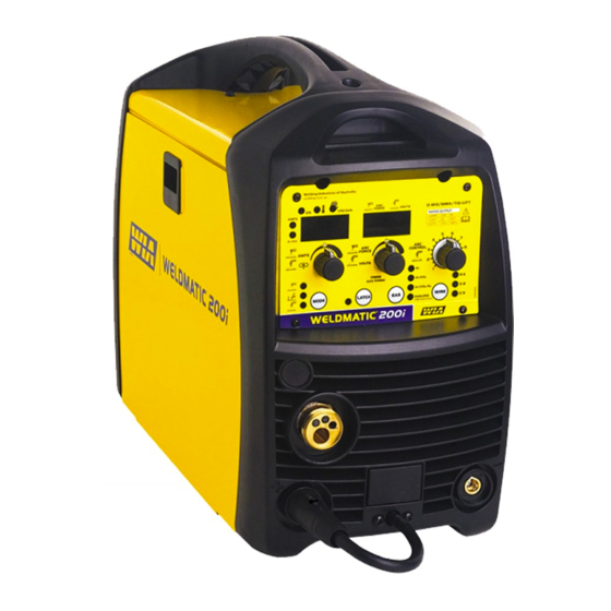
- Page 1 ® Weldmatic 200i [internal wirefeeder] Operators Manual Weldmatic 200i MIG, Arc/TIG welder Model No. CP137-2, Iss A 02/15 CP137-40 Rev A...
- Page 2 Welding Industries of Australia A division of ITW Australia Pty Ltd 1300 300 884 Info@welding.com.au welding.com.au...
-
Page 3: Table Of Contents
Weldmatic 200i Contents Section General Information Page Safe Practices Introduction Receiving Specifications Controls Installation Normal Welding Sequence Basic Welding Information General Maintenance External Trouble Shooting Service Information 10.1 Circuit Diagram Assembly and Parts Lists 11.1 Power Source 11.2 Wirefeed assembly 11.3 Gun and Cable Assembly 27 Warranty information Model No CP137, Iss A 02/15... -
Page 4: Safe Practices
Operators Manual Safe practices when using Read First welding equipment The information contained in this These notes are provided in the interests manual is set out to enable you of improving operator safety. They should to properly maintain your new be considered only as a basic guide to Safe equipment and ensure that you obtain Working Habits. -
Page 5: Fire And Explosion Prevention
Weldmatic 200i Burn protection coating is removed from the work surface, the area is well ventilated, or the operator The welding arc is intense and visibly bright. wears an air-supplied respirator. Its radiation can damage eyes, penetrate Work in a confined space only while it is light-weight clothing, reflect from light- being ventilated and, if necessary, while coloured surfaces, and burn the skin and... - Page 6 Operators Manual A person acting as Fire Watcher must be Shock Prevention standing by with suitable fire extinguishing Exposed conductors or other bare metal equipment during and for some time after in the welding circuit, or ungrounded welding or cutting if; electrically alive equipment can fatally shock •...
-
Page 7: Introduction
WIA supplies a wide range of mild steel and steel to aluminium alloys. special purpose electrodes which cater for home workshop, rural, and industrial requirements. -
Page 8: Receiving
Operators Manual 2 Receiving Austarc 16TC, Classification E4916-A Check the equipment received against the shipping invoice to make sure the shipment A low hydrogen electrode with good is complete and undamaged. If any damage arc stability and out-of-position welding has occurred in transit, please immediately characteristics. -
Page 9: Specifications
Weldmatic 200i 3 Specifications Manufactured to Australian Standard If the supply cable is damaged it must AS60974.6. be replaced by the manufacturer, their service agent or a similarly qualified Primary Voltage person. 240 Vac, 50/60 Hz Rated Primary Current (I eff) Circuit Breaker Rating Mains 14 Amps... -
Page 10: Controls
Operators Manual 4 Controls AMPS FORCE CONTROL VOLTS GASLESS 0.8/0.9/1.2 mm Fig 1 Weldmatic 200i Controls 1 Control Panel 9 Over Temperature Indicator This light is on if the machine overheats 2 Euro Gun/Cable Connector or mains voltage os too high or low – the 3 Positive Welding Output Terminal machine will prevent weld output until the machine has cooled down or mains voltage... -
Page 11: Arc Control
Weldmatic 200i 12 Digital Display – Amps or m/min 15 Arc Control During welding actual welding Amps will be When in MIG (GMAW) mode the harshness displayed and then held for 30 seconds after of the arc can be adjusted. the end of the weld. -
Page 12: Installation
Operators Manual 5 Installation Connection to Electrical Mains Power Output Voltage Polarity Supply The design of the Weldmatic 200i allows The Weldmatic 200i is factory fitted with a selection of the output voltage polarity. 3 metre, 3 core 2.5mm Heavy Duty PVC Positive Wire mains power supply cable with moulded 3 pin, 15 Amp, Single Phase plug. - Page 13 Weldmatic 200i Fitting the Consumable Wire (-) output terminal Remove the spool holder knob, spring and (+) output flange. Fit the spool of welding wire. Refit Polarity terminal selection cable the spool holder knob, spring and flange. Check the adjustment of the spool adjuster, which should be set to prevent over run of Work the wire spool at the end of a weld, without...
-
Page 14: Normal Welding Sequence
For best results when welding mild steel, we In draft-free conditions the gas flow rate recommend quality WIA AUSTMIG ES6. required to give adequate protection is Dirty, rusty or kinked wire will not feed typically 10-12 litres/min. In situations where... - Page 15 Weldmatic 200i Establishing a Weld Setting A “good” weld will have the characteristics illustrated in Figure 4. The weld has penetrated Once the consumable wire type, wire size into the parent metal, fusing the root of the and shielding gas have been chosen, the two joint where the two plates meet, and the weld variables that are adjusted in order to obtain blends smoothly into the side walls.
- Page 16 Operators Manual Weldmatic 200i Settings Chart Suggested Settings for Fillet Weld Mild Steel – Gasless Wire Wire type • Gasless / Flux Cored • Negative Polarity • 4.5kg Spool • Knurled Drive Roll • Arc Control 1 Wire Size Material 0.8mm 0.9mm 1.2mm...
- Page 17 Weldmatic 200i Weldmatic 200i Settings Chart (cont) Suggested Settings for Fillet Weld Mild Steel – Solid Wire Wire type • Carbon Steel ES6 • Positive Polarity • 5kg Spool • Gas: Ar + 5% CO + 2% O • Arc Control 5 Wire Size Material 0.6mm...
- Page 18 Operators Manual Weldmatic 200i Settings Chart (cont) Suggested Settings for Fillet Weld Mild Steel – Solid Wire Wire type • Carbon Steel ES6 • Positive Polarity • 5kg Spool • Gas: Ar + 18% CO • Arc Control 5 Wire Size Material 0.6mm 0.8mm...
- Page 19 Weldmatic 200i Gun Position For “down hand” fillet welding with gas shielded solid wires, the gun is normally positioned as shown in Figure 7a below, with the nozzle end pointing in the direction of travel. For “down hand” fillet welding with gasless flux cored wires, the gun is normally positioned as shown in Figure 7b, with the nozzle end pointing away from the direction...
- Page 20 Select an appropriate welding current for the electrode diameter by setting the knob Connection for TIG Welding on the machine front panel. WIA AUSTARC For TIG welding, the torch is connected to electrodes will give the best results. the negative terminal. Figure 9 illustrates...
-
Page 21: Duty Cycle
Weldmatic 200i Duty Cycle TIG Welding Operation The term duty cycle indicates the percentage Connect the Work Clamp to the work piece. welding time available at the rated output Turn on the power switch located on the rear current, for each 10 min period over 4 hours. panel. -
Page 22: General Maintenance
Operators Manual 8 General Maintenance 3 Welding tip is free of obstructions such Before removing the equipment as spatter build-up. Ream out the tip cover, ENSURE that the equipment bore with a suitable size oxy-tip cleaner. is disconnected from the mains Replace the welding tip as it becomes power supply. -
Page 23: External Trouble Shooting
If the following checks do not identify the fault condition, the equipment 1 Check the rating of the mains supply should be returned to a WIA Service circuit breaker. The Weldmatic 200i agent. Phone 1300 300 884 for details should be supplied from a 20 Amp or of your nearest service agent. -
Page 24: Service Information
Operators Manual 10 Service Information Porosity in weld caused by lack of The following information is intended shielding gas for use by qualified service personnel. 1 Check that the correct gas flow rate has When the unit is energised LETHAL been set (refer page 12) VOLTAGES are present on the electrical and electronic components. -
Page 25: Circuit Diagram
Weldmatic 200i 10.1 Circuit Diagrams – Power Source Fig 11 Weldmatic 200i Circuit Diagram Model No CP137, Iss A 02/15... -
Page 26: Power Source
Operators Manual 11.1 Assembly and Parts List - Weldmatic 200i Power Source Fig 12 Weldmatic 200i Power Source Assembly Trusted by the best... - Page 27 Weldmatic 200i Item # Part # Description PAN154 Outer Cover M0059 Handle M0060 Rear Panel E0041 Gas Valve E0078 Main Switch FAN011 PWA019 Main Control Panel PCB PWA020 Wirefeeder Control PCB M0063 Front Panel SA140-0/2 Dinse Socket PWA021 Front Panel Control PCB WIN540 Front Panel Sticker M0058...
-
Page 28: Wirefeed Assembly
Operators Manual 11.2 Assembly and Parts List - Wirefeeder Fig 13 Wirefeed Assembly Item # Part # Description W27-0/9 Retaining Screw Feed Rolls Item # Part # Description W26-0/8 0.6 + 0.8mm, Solid Wire W26-8/8 0.8 + 0.9mm, Solid Wire W26-7/8 1.0//1.2mm, Flux Cored Wire (knurled) W26-9/8... -
Page 29: Gun And Cable Assembly
Weldmatic 200i 11.3 Assembly and Parts List - Gun and Cable Assembly Fig 14 GUN001 (200 amp) Gun and Cable Assembly Item # Part # Description BE4392 Nozzle, Brass, Tapered see ‘Tips’ page 28 Contact Tip BE4335 Gas Diffuser (Head) BE4323 BEQT2-45 Body Tube, 2”, 45... - Page 30 Operators Manual Tips Wire diameter Short series (25mm) 0.6mm BE7497 0.8mm BE7488 0.9mm BE7489 1.0mm BE7496 1.2mm BE7490 To replace liner: Disconnect gun/cable assembly at the Euro adaptor. Remove nozzle (1) and head (3). Withdraw old liner from the wirefeeder end. Insert new liner and refit gun/cable assembly to the wirefeeder.
-
Page 31: Warranty Information
2 Year Warranty Statement • The customer being able to provide Welding Industries of Australia (WIA) proof of purchase of the Product and the warrants to the original retail purchaser purchase price paid for the Product;... - Page 32 WIA Blue Helmet Part No: 235620 DESIGNED FOR THE WELDER WHO WANTS PROTECTION, PERFORMANCE & COMFORT AT AN AFFORDABLE PRICE. • Lens and helmet comply with • 1 year warranty Australian Standards AS/NZS (Auto-Darkening lens only) 1338.1 (Auto-Darkening) and AS/ •...
Need help?
Do you have a question about the Weldmatic 200i MIG and is the answer not in the manual?
Questions and answers