Linear AE-100 Installation And Programming Instructions
Commercial telephone entry system
Hide thumbs
Also See for AE-100:
- Facility manager’s manual (24 pages) ,
- Installation and programming instructions (36 pages)

Related Manuals for Linear AE-100


Summary of Contents for Linear AE-100
- Page 1 AE-100 Commercial Telephone Entry System Installation and Programming Instructions USA & Canada (800) 421-1587 & (800) 392-0123 (760) 438-7000 - Toll Free FAX (800) 468-1340 www.linearcorp.com...
-
Page 2: Table Of Contents
Optional features that the AE-100 supports are provisions for postal lock and color CCTV camera installation. The AE-100 is powered from a 16 VAC plug-in transformer and supports an internal rechargeable 1.2 amp/hour backup battery (not included). The battery charging circuit will support an external backup battery with up to 7 amp/hour capacity. -
Page 3: Feature Overview
The postal lock itself is not supplied, it must be purchased from your local post offi ce. When the postal lock is installed inside the front panel of the AE-100, it will press a microswitch when the postal key is turned, activating the access relay. -
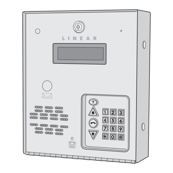
Page 4: Component Locations
EARTH GROUND EARTH GROUND CONNECTOR BACKUP BATTERY (OPTIONAL) SPEAKER POSTAL LOCK MICROSWITCH DISPLAY CONTRAST ADJUSTMENT POSTAL LOCK (OPTIONAL) CAMERA CONNECTOR TELEPHONE JACK TELEPHONE TERMINALS KEYPAD JACK BATTERY CONNECTOR STUD CCM-1 CAMERA (OPTIONAL) MICROPHONE DISPLAY KEYPAD LIGHTING SPEAKER CONNECTOR CONNECTOR VIDEO OUT... -
Page 5: Wiring Diagram
4. INTERNAL BATTERY CHARGER WILL SUPPORT UP TO A 7 AMP/HOUR BACKUP BATTERY 5. CONNECT THE CASE GROUND STUD TO A GOOD QUALITY EARTH GROUND WITH 12 AWG SOLID WIRE 6. DO NOT USE THE AE-100 TRANSFORMER TO POWER THE DOOR STRIKE! CASE... -
Page 6: Important Mounting Requirements
Mounting Location If the AE-100 is used to control a door or pedestrian gate, locate the unit as near as practical to the entry point. If the unit is mounted on or in a wall adjacent to the entry point, be sure the wall is sturdy. The repeated shock and vibration from a slamming access door or spring-loaded pedestrian gate must be isolated from the AE-100. -
Page 7: Entry System Mounting
External Alarm Contacts In installations where vandalism is a concern, an internal normally closed alarm contact may be added as a tamper switch to the AE-100 providing a trigger source for an external alarm panel. If the AE-100 cabinet is opened for any reason, the internal alarm contact will trigger the external alarm panel, reporting the alarm to a central monitoring station or other alarm reporting location. -
Page 8: Entry System Mounting (Continued)
Entry System Mounting (Continued) Recessed Mounting The cabinet can be mounted recessed using the accessory trim-ring Model TR-100 (P/N ACP00941). The trim-ring mounts in the wall and the cabinet attaches to the trim-ring. 1. Identify the location of any studs in the wall. ✦... -
Page 9: Access Relay Wiring
3. Connect one wire from the power supply to one wire from the locking device. 4. Route two wires between the locking device and the AE-100. Connect one wire to the remaining wire of the locking device. Connect the other wire to the remaining wire of the power supply. -
Page 10: Multiple Unit Telephone Wiring
Multiple Unit Telephone Wiring Up to four AE-100 units may be connected to the same dedicated telephone line to form a simple network. Connecting multiple units allows transferring programming data (either the directory entries only or the entire memory’s contents) from the “master” unit to the other sub-units. -
Page 11: Power, Battery, & Ground Wiring
AE-100 16 VAC terminals. Backup Battery Use of a battery backup is optional. It will allow the AE-100 to operate for short periods of time without AC power. The door or gate access device must use some type of battery backup of its own for the entire system to be functional. -
Page 12: Optional Postal Lock
Optional Postal Lock A postal lock can be installed in the AE-100 Entry System to provide keyed access for the postal service. The AE-100 case is designed to accept a U.S. Postal Service postal lock. When the postal lock is engaged the access relay will activate. -
Page 13: Programming Reference & Factory Defaults
DELETE ALL RESIDENT DATA DELETE ALL STAND-ALONE ENTRY CODES TOTAL MEMORY RESET FUNCTION OF PROGRAMMING STEP SYSTEM OPTIONS ACCESS DATA CONTROL SYSTEM UTILITIES FACTORY DEFAULT VALUE 123456 NOT SET ENGLISH 3 TRIES 4 SECONDS LINEAR ACCESS TELEPHONE ENTRY 60 SECONDS... -
Page 14: Automatic Programming Method Selection
Access to Programming To make it easy for installers familiar with Linear’s and other manufacturer’s access control systems, two methods of programming are available. Programming Position Numbers (or Function Codes) that match other equipment help the installer to make quick programming changes with keystrokes they’ve used before. -
Page 15: Programming Over The Telephone
Programming Over the Telephone Most system commands can be programmed using a TouchTone™ telephone. The telephone’s keypad will act similar to the AE-100’s keypad. Both programming methods can be used over the telephone. Connecting with a Telephone 1. Place a call to the telephone number of the line that the AE-100 is connected to. -
Page 16: Multi-Unit Installations
Multi-unit Installations Up to four AE-100 units may be connected to the same dedicated telephone line to form a simple network. Connecting multiple units allows transferring programming data (either the directory entries only or the entire memory’s contents) from the “master” unit to the other sub-units using the system utility commands. -
Page 17: Resident Data Programming
4. Enter the Name of the resident to be displayed (up to 16 characters). 5. Press 6. Enter the resident’s Telephone Number (up to 14 digits). Press and hold down the , or key to enter 1-4 two-second pauses. Hold down the key for about two seconds. -
Page 18: Stand-Alone Entry Code Programming
Stand-alone Entry Code Programming A Stand-alone Entry Code is a number entered at the AE-100 keypad to request access. Up to 125 4-digit Stand-alone Entry Codes can be set. ✦ NOTE: Each Stand-alone Entry Code programmed reduces the possible number of Directory Entries by one. -
Page 19: System Options (Continued)
2. Enter the time (in seconds) for access relay to stay activated (04-99) 3. Press Welcome Display Text The AE-100 display will show a visitor a welcome message alternating with instructions on how to fi nd and call a resident. The welcome message can be customized to suit the installation. -
Page 20: System Options (Continued)
Resident Control of Access Relay The factory setting allows the resident to activate the access relay by pressing the 9 key on their telephone when a call from the AE-100 is received. This feature can be disabled. Disabling this feature will only allow access by using resident Entry Codes and Stand-alone Entry Codes at the unit’s keypad. -
Page 21: System Utility Commands
AC power and low backup battery. In multi-unit installations, the master unit logs communication errors with sub-units. ✦ NOTE: This step cannot be performed remotely through the telephone. 1. Press 2. The display will show any errors pending. -
Page 22: System Utility Commands (Continued)
2. The display will show the unit numbers that responded on the fi rst try error free. 3. Enter another programming step number followed by Display System Information The version of the fi rmware installed in the AE-100 can be displayed. ✦ NOTE: This step cannot be performed remotely through the telephone. 1. Press 2. -
Page 23: Alternate Programming Section
Alternate Programming Section To make it easy for installers familiar with Linear’s and other manufacturer’s access control systems, two methods of programming are available. Function Codes that match other equipment help the installer to make quick programming changes with keystrokes they have used before. -
Page 24: Alternate Programming Reference
4. Delete unused Directory Codes to avoid running out of memory. Step 4 Enter the tenant’s Telephone Number (up to 14 digits), press # after each number, then # 5. Tenant Names can be entered in any order. The system again after the last number. - Page 25 Step 5 To keep the Telephone Number press # and skip to Step 7. Step 6 To change the Telephone Number press ✱ then enter a new Telephone Number (up to 14 digits), press # after each number, then # again after the last number.
- Page 26 All systems must have one unit set to #1. ALTERNATE PROGRAMMING METHOD LOCAL PROGRAMMING TELEPHONE PROGRAMMING Step 1 Enter Function Code 05 and press #, one short beep sounds. Step 2 Enter the number of hours from 01-98 to energize the access relay, then press #.
- Page 27 Step 2 Enter the new 4-digit Stand-alone ACCESS CODE Access Code, then press #. A Stand-alone Access Code is a number entered at the AE-100 keypad to request access. Up to 125 4-digit Stand-alone Access Step 3 Enter the new 4-digit Stand-alone Codes can be set.
- Page 28 5# will cancel the command.) NOTE: To allow for multi-unit network communications, when executing this command remotely over the telephone, the system will disconnect your call after Step #3 then copy the data from the master unit to the sub-units.
- Page 29 Step 2 The display will show the model number The Model number and fi rmware and fi rmware version number of the version installed in the AE-100 fi rmware installed in the unit. can be displayed. Step 3 Press #.
- Page 30 (default). relay by pressing the 9 key on their telephone when a call from Step 3 Press #. the AE-100 is received. This feature can be disabled. Disabling this feature will only allow access by using resident Access Codes and Stand-alone Access Codes at the unit’s keypad.
- Page 31 FUNCTION CODE Step 1 To exit programming mode, enter Function Code 91, then press #. EXIT NOTE: The AE-100 will automatically exit Programming PROGRAMMING Mode after fi ve minutes of programming inactivity MODE Entering this command number will cause the unit to exit programming mode and return to normal operation.
-
Page 32: System Adjustments
System Diagnostics Several components on the main circuit board are for monitoring the system during operation. When calling for technical assistance, Linear’s Technical Services Department may ask the installer to use these components to diagnose the system. -
Page 33: Ae-100 Operation
90 seconds. Resident Call-back If the resident call-back feature is enabled, resident’s can call the AE-100 to talk to a visitor and grant access. The call-back must be made within 60 seconds after the visitor’s missed call. -
Page 34: Specifi Cations
Specifi cations MECHANICAL Case dimensions: 9-3/4” W x 11-3/4” H x 3-1/2” D ELECTRICAL Input Power: 16 VAC from supplied plug-in transformer Current Consumption: < 200 mA idle, < 500 mA operating Backup Battery: 12 Volt sealed lead-acid gel cell (not included) Built-in charger with up to 7 A/H battery capacity Access Relay: Form “C”... -
Page 35: Troubleshooting
All implied warranties, including implied warranties for merchantability and implied warranties for fi tness, are valid only until the warranty expires. This Linear LLC Warranty is in lieu of all other warranties express or implied. All products returned for warranty service require a Return Product Authorization Number (RPA#). - Page 36 Copyright © 2008 Linear LLC 225787 C...
Need help?
Do you have a question about the AE-100 and is the answer not in the manual?
Questions and answers
Where can I find someone to install it?