Table of Contents
Advertisement
Quick Links
Advertisement
Table of Contents

Related Manuals for andrews OFS25


Summary of Contents for andrews OFS25
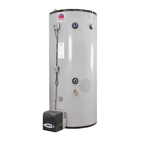
- Page 1 This manual must be kept with the appliance October 2010 Part No E524 Oil Fired Installation Guide, Operation and Service Manual Oil Fired Storage Water Heaters MODELS OFS25, OFS29, OFS63, OFS90, OFS108, OFS163 Working towards a cleaner future...
- Page 2 The attention of U.K. users is drawn to their responsibilities under the Health and Safety Regulations 1993. All installation and service on the Andrews Water Heater must be carried out by properly qualified personnel, and therefore no liability can be accepted for any damage or malfunction caused as a result of intervention by unauthorised personnel.
-
Page 3: Table Of Contents
Burner Spares BTL6 OFS63 Heater Spares OFS90 Burner Spares BTL10 OFS90 Heater Spares OFS108 Burner Spares BTL10 OFS108 Heater Spares OFS163 Burner Spares BTL20 OFS163 Unvented System Kit OFS25 & OFS29 Unvented System Kit OFS63 & OFS90 Unvented System Kit OFS108 & OFS163... -
Page 4: General And Safety Information
SECTION 1 GENERAL AND SAFETY INFORMATION GENERAL The Andrews Water Heater has been designed and manufactured to give an efficient, reliable and long service life. INFORMATION To ensure the continued, trouble-free operation of your heater at maximum efficiency, it is essential that correct installation, commissioning, operation and service procedures are carried out strictly in accordance with the instructions given in this manual. -
Page 5: Health And Safety Regulations 1993
1993 Andrews Water Heaters should only be used in the manner and purpose for which they were intended and in accordance with the instructions in this manual. Although the heaters have been manufactured with paramount consideration to safety, certain basic precautions specified in this manual must be taken by the user. -
Page 6: Technical Data
SECTION 2 TECHNICAL DATA ANDREWS MODEL NO. OFS25 OFS29 OFS63 OFS90 OFS108 OFS163 Storage Cap Ltrs Storage Cap Galls Rec Thro 44c 1227 1759 2110 3166 Rec Thro 44c Rec Thro 56c 1398 1677 2516 Rec Thro 56c Heat Input 30.8... - Page 7 TECHNICAL DATA SECTION 2 ANDREWS MODEL NO. OFS25 OFS29 OFS63 OFS90 OFS108 OFS163 Flexible Hose Connection Size 0.25 0.25 0.25 0.25 0.25 0.25 Fuel Cons. Kero 10.8 12.9 19.4 Fuel Cons. Kero 0.70 0.81 1.65 Fuel Cons. Gas Oil 10.3 12.4...
-
Page 8: Installation
Service clearance above all the heaters except heater models OFS25 should be 1270mm for removal of the flue baffle. Heater model OFS25 flue baffle is hinged for low ceiling removal. It is very important that heater models OFS108 & OFS163 have at least 600mm clearance at the rear for the installation and removal of the T/P valve if fitted. - Page 9 INSTALLATION SECTION 3 BURNER The burners are supplied complete with pre-wired control thermostat loom to a harness plug with connects to the harness socket on the burner. The burners are supplied with ASSEMBLY the flange fitted to the burner blast tube in the correct position. A gasket is also supplied loose in the burner carton.
-
Page 10: Flue Systems
SECTION 3 INSTALLATION FLUE SYSTEMS Detailed recommendations for flue installation are given in BS5410 PT 1 and BS5410 PT 2 The Building Regulations allow the use of stainless steel under the term “Deemed to Satisfy” but the minimum thickness must be 0.71mm (22swg). We recommend that Selkirk SMW Flue System is used to the following specification: Twin Wall, Insulated, Stainless Steel. -
Page 11: Flue Systems
Assembly of Draught Stabiliser Approx Height SYSTEMS Tee with draught stabiliser Flue kit 6” fitted E013 OFS25 = 1949mm Spigot Adaptor OFS29 = 2000mm Heater Outlet Spigot Crimped Adaptor Fig. 2 The flue should provide a negative pressure at the base of the flue between -1.1mm (0.03”w.g) and -2.00mm (0.06”w.g.). -
Page 12: Common Flue Header
SECTION 3 INSTALLATION COMMON FLUE HEADER Must have vertical flue discharge Draught Draught Stabiliser Stabiliser Fig. 4 It is recommended that individual flues are used for each heater. However if a common flue header is to be used the following guidelines must be used. 1. -
Page 13: Air Supply And Ventilation
INSTALLATION SECTION 3 The following notes are intended to give general guidance: AIR SUPPLY Where the heater is to be installed in a room or internal space the heater requires the room or internal space containing it to have a permanent air vent. The vent must be VENTILATION either direct to outside air or to an adjacent room or internal space which must itself have a permanent vent of at least the same size direct to outside air. -
Page 14: Water Quality And Treatment
BEMS version is available, which provides a remote warning signal. These anodes are available as an optional extra on all Andrews Water Heaters. In hard water areas, scale formation can occur in hot water systems and hot water heaters and the higher the temperature and volume of water used, the more problematic the scale build-up can be. -
Page 15: Water Connections- Hydrojet System
INSTALLATION SECTION 3 WATER CONNECTIONS Hydrojet System Top Cold Inlet Connection The upper “jet ports” direct the flow outward to begin the dynamic mixing action. The lower “jet ports” direct the flow inward to increase the turbulence. Tank Heater Casing All models now incorporate the new Mini Hydrojet system on cold inlet side connections. -
Page 16: Water Connections Vented Systems
SECTION 3 INSTALLATION WATER The water heater must be supplied from a cold water feed cistern and the hot water supply pipe must be fitted with an open vent pipe in accordance with BS 5546 and CONNECTIONS BS 6644. VENTED SYSTEMS The Water Supply (Water Fittings) Regulations 1999 must be observed when installing the system. - Page 17 INSTALLATION SECTION 3 WATER All connection sizes are CONNECTIONS shown on page 5 Cold Inlet/Hot Outlet on models OFS25 OFS29 OFS108 Front Cold Inlet/Hot Outlet OFS63 OFS90 T & P Valve Tapping OFS108 OFS163 Optional Rear Cold Inlet/Hot Outlet Drain &...
-
Page 18: Water Connections Unvented Systems
WATER Unvented Systems should be fitted by an Approved Installer CONNECTIONS When used in an unvented system, the Andrews water Heater will supply hot water at a UNVENTED pressure of 3.5bar (51lbf/in ), provided that this pressure is available at the mains feed. - Page 19 Installation of unvented hot storage water systems must comply with Part G of Schedule 1 of the Building Regulations 1991. Typical water service layout for single heater unvented system is shown in Fig. 7. Top Entry Models OFS25 OFS29 OFS108 Front Rear Entry...
-
Page 20: Electrical Supply
SECTION 3 INSTALLATION ELECTRICAL Wiring external to the water heater must be installed in accordance with the I.E.E. Regulations for the wiring of buildings and to any local regulations that may apply. SUPPLY The heaters are designed to run off 220/240V 1 Ph 50 Hz supply and the fuse rating is 5 Amp See pages 4 &... -
Page 21: Fuel Supply
INSTALLATION SECTION 3 A fire valve and filter must be fitted in the fuel supply to the burner. (Not Supplied). FUEL SUPPLY Current standards state that the "BIO-FUEL" has a blend of between 7% and 10%. If a higher blend is being used then the burner manufacturer MUST be contacted for additional guidance. Use either Kerosene Class C2 (BS2869) or Gas Oil Class D (BS2869). -
Page 22: Commissioning
SECTION 4 COMMISSIONING IMPORTANT: These oil fired water heaters must be commissioned by a competent engineer. CAUTION / IMPORTANT: PRESSURE WITHIN COMBUSTION CHAMBER SHOULD READ BETWEEN -0.2 MBAR AND -0.5 MBAR, ADJUST THE DRAUGHT STABILIZER TO ENSURE A READING OF -0.1" TO -0.4" IS ACHIEVED TO ENSURE SAFE AND CORRECT OPERATION. CAUTION: DO NOT OPERATE THE WATER HEATER UNTIL THE STORAGE VESSEL IS COMPLETELY FILLED WITH WATER. -
Page 23: Air Adjustment
4. Air damper in open position (9) 5. Air damper in closed position (0) 6. Air Damper Fixing Screw When the combustion adjustment is complete the following combustion analysis readings will be achieved. ADJUSTMENT Andrews Model No OFS25 OFS29 OFS63 OFS90 OFS108 OFS163... -
Page 24: Instructing The Users
SECTION 4 COMMISSIONING When satisfactory commissioning and testing has been achieved, hand this manual to the INSTRUCTING user or purchaser and explain the method of economic and efficient operation. THE USERS Explain that: 1. Other than for long shutdown periods, the heater must be left operating normally. 2. -
Page 25: Operation
This is normal and will disappear when the heater warms up. The thermostats fitted to heater models OFS25, OFS29, OFS63 & OFS90 have a built in high limit thermostats. In the case of dangerous water temperatures the fuel supply will be automatically shut off. -
Page 26: Servicing
SECTION 6 SERVICING INTRODUCTION Servicing must be carried out be a properly qualified person. Whilst giving these instructions for the care of the Heater, it is recommended that checks are carried out by the installer at least every 6 months. Ensure good ventilation by keeping the heater free of extraneous materials and clear of dust and lint. -
Page 27: Magnesium Anode(S)
3. If the anode is encrusted with limescale, it should be either wire brushed to reveal bright metal or replaced. 4. For models OFS25 & OFS29 withdraw the hot water outlet nipple/anode and replace (See Fig. 9) - Refer to parts list pages 32 & 32. -
Page 28: Cleaning The Storage Vessel All Models
Note: It is recommended that a new anode is fitted. Add suitable hydrochloric based descale acid, the requirement is normally 5 litres for OFS25 & OFS29 and 10 for OFS63, OFS90, OFS108 & OFS163. After a minimum of one hour relight the burner for 2 minutes (Maximum). -
Page 29: Fault Finding
FAULT FINDING SECTION 7 ALL MODELS FAULT FAULT ACTION ACTION (a) Check electrical supply and ON/OFF switch is ‘ON’. 1. BURNER WILL NOT START (b) Check thermostat circuit is made and also time clock contacts are closed and limit thermostat is set. (c) Check if locked out. -
Page 30: Parts Lists And Illustrations
SECTION 8 PARTS LIST AND ILLUSTRATIONS HEATER SPARES OFS25 Ref. Part No. Description Qty. E707 Cold Inlet Dip Tube E708 Hot Outlet Nipple Anode E709 Flue Baffle (Hinged) C333 Articulated Service Anode C381 Drain Valve C103 Drain Valve Socket C247... -
Page 31: Burner Spares Btl4 Ofs25
PARTS LIST AND ILLUSTRATIONS SECTION 8 BURNER SPARES BTL4 OFS25 Ref. Part No. Description Qty. E676 Blast Tube E679 Brake Plate E683 Electrode E685 H.T. Cable E687 E689 Photocell E691 Transformer E694 Transformer Cable E696 Control Box E699 Motor E702... -
Page 32: Heater Spares Ofs29
SECTION 8 PARTS LIST AND ILLUSTRATIONS HEATER SPARES OFS 29 Ref. Part No. Description Qty. E710 Cold Inlet Dip Tube E711 Hot Outlet Nipple Anode E712 Flue Baffle (Hinged) C333 Articulated Service Anode C381 Drain Valve C103 Drain Valve Socket C247 Drain Valve Nipple C719... - Page 33 PARTS LIST AND ILLUSTRATIONS SECTION 8 BURNER SPARES BTL 4 OFS 29 Ref. Part No. Description Qty. E676 Blast Tube E679 Brake Plate E683 Electrode E685 H.T. Cable E687 E689 Photocell E691 Transformer E694 Transformer Cable E696 Control Box E699 Motor E702 Pump...
-
Page 34: Heater Spares Ofs63
SECTION 8 PARTS LIST AND ILLUSTRATIONS HEATER SPARES OFS 63 (Rear) (Rear) Ref. Part No. Description Qty. C333 Articulated Service Anode C534 Hot Outlet Nipple 1.5 BSP E050 Hydrojet Hot Outlet / Cold Inlet Nipple 1.5 BSP E713 Flue Baffle C299 Cleanout Pad Seal C381... -
Page 35: Burner Spares Btl6 Ofs63
PARTS LIST AND ILLUSTRATIONS SECTION 8 BURNER SPARES BTL6 OFS63 Ref. Part No. Description Qty. E676 Blast Tube E680 Brake Plate E683 Electrode E685 H.T. Cable E687 E689 Photocell E691 Transformer E694 Transformer Cable E696 Control Box E699 Motor E702 Pump E610 Nozzle - Kerosene - 1.65 x 80’s... -
Page 36: Heater Spares Ofs90
SECTION 8 PARTS LIST AND ILLUSTRATIONS HEATER SPARES OFS 90 (Rear) (Rear) Ref. Part No. Description Qty. C333 Articulated Service Anode C534 Hot Outlet Nipple 1.5 BSP E050 Hydrojet Hot Outlet / Cold Inlet Nipple 1.5 BSP E713 Flue Baffle C299 Cleanout Pad Seal C381... -
Page 37: Burner Spares Btl10 Ofs90
PARTS LIST AND ILLUSTRATIONS SECTION 8 BURNER SPARES BTL10 OFS90 Ref. Part No. Description Qty. E677 Blast Tube E687 E681 Brake Plate E685 H.T. Cable E683 Electrode E689 Photocell E692 Transformer E694 Transformer Cable E697 Control Box E700 Motor E702 Pump E614 Nozzle - Kerosene - 2.50 x 80’s... -
Page 38: Heater Spares Ofs108
SECTION 8 PARTS LIST AND ILLUSTRATIONS HEATER SPARES OFS108 (Rear) (Rear) Ref. Part No. Description Qty. E714 Cold Inlet Dip Tube C534 Hot Outlet Nipple 1.5 BSP E050 Hydrojet Hot Outlet / Cold Inlet Nipple 1.5 BSP C333 Articulated Service Anode E715 Flue Baffle E716... -
Page 39: Burner Spares Btl10 Ofs108
PARTS LIST AND ILLUSTRATIONS SECTION 8 BURNER SPARES BTL10 OFS108 Ref. Part No. Description Qty. E677 Blast Tube E687 E681 Brake Plate E685 H.T. Cable E683 Electrode E689 Photocell E692 Transformer E694 Transformer Cable E697 Control Box E700 Motor E702 Pump E705 Nozzle - Kerosene - 3.00 x 80’s... -
Page 40: Heater Spares Ofs163
SECTION 8 PARTS LIST AND ILLUSTRATIONS HEATER SPARES OFS163 (Rear) (Rear) (Not Shown) Ref. Part No. Description Qty. C333 Articulated Service Anode C534 Hot Outlet / Cold Inlet Nipple 1.5 BSP E050 Hydrojet Cold Inlet Nipple 1.5 BSP E717 Flue Baffle C299 Cleanout Pad Seal C381... -
Page 41: Burner Spares Btl20 Ofs163
PARTS LIST AND ILLUSTRATIONS SECTION 8 BURNER SPARES BTL20 OFS163 Ref. Part No. Description Qty. E678 Blast Tube E688 E682 Brake Plate E686 H.T. Cable E684 Electrode E690 Photocell E693 Transformer E695 Transformer Cable E698 Control Box E701 Motor E702 Pump E706 Nozzle - Kerosene - 4.50 x 80’s... -
Page 42: Unvented System Kit Ofs25 & Ofs29
SECTION 8 PARTS LIST AND ILLUSTRATIONS UNVENTED SYSTEM KIT OFS25 & OFS29 Ref. Part No. Description Qty. B171 Unvented Systems Kit Complete C780 Pressure Reducing Valve/Strainer C781 Check Valve / Expansion Valve C782 Expansion Vessel E462 Temperature/Pressure Relief Valve C783... -
Page 43: Unvented System Kit Ofs63 & Ofs90
PARTS LIST AND ILLUSTRATIONS SECTION 8 UNVENTED SYSTEM KIT OFS63 & OFS90 Ref. Part No. Description Qty. B172 Unvented Systems Kit Complete C784 Pressure Reducing Valve/Strainer C785 Check Valve C782 Expansion Vessel C380 Temperature/Pressure Relief Valve C384 Tundish C786 Expansion Valve B173 Wall Mounting Kit (Optional) C788... -
Page 44: Unvented System Kit Ofs108 & Ofs163
SECTION 8 PARTS LIST AND ILLUSTRATIONS UNVENTED SYSTEM KIT OFS108 & OFS163 Ref. Part No. Description Qty. B267 Unvented Systems Kit Complete C784 Combined Reducing Valve/Strainer C785 Check Valve C786 Expansion Valve C782 Expansion Vessel (25 Litre) E675 Temperature/Pressure Relief Valve 2” C908 2”... - Page 45 Baxi Commercial Division Sales: Technical: Wood Lane, Erdington, 0845 070 1056 0845 070 1057 Birmingham B24 9QP Email: andrews@baxicommercialdivision.com www.andrewswaterheaters.co.uk...
Need help?
Do you have a question about the OFS25 and is the answer not in the manual?
Questions and answers