
Summary of Contents for Pure Blue H20 PB-TLRO4H50T
- Page 1 REVERSE OSMOSIS W TER FILTR TION SYSTEM MODEL PB-TLRO4H50T INSTRUCTION M NU L Pure lue H20, LLC 13813 Monroes Business Park Tampa, FL 33635 USA www.pureblueh2o.com (844) 787-3148 • (844) PURE-1-4-U 2015.06.30 #8739 PAW...
-
Page 2: Operational Parameters
Copper Tube: Reverse Osmosis water should not be run through copper tube as the purity of the water will leach copper, which will cause an undesired taste in water and pin holes may form in the tube. Note: Polytubing is recommended. Maintenance of Filters for Model PB-TLRO4H50T: Part Number Description... -
Page 3: Required Tools And Materials
REQUIRED TOOLS & MATERIALS • Tape Measure • 1/8” & 1/4” Drill Bits • Phillips Head Screwdriver • Pencil • Adjustable Wrench • Safety Glasses • Utility Knife • Drill • Pan or Bucket PACKAGE CONTENTS Flow... -
Page 4: Installation Overview
PREPARE SITE FOR INSTALLATION 1 Prior to starting, close the cold water shut-off valve. 2 Temporarily place tank and filter assembly into cabinet to ensure adequate space and proper positioning. Note: For filter installation, see page 5, STEP THREE, Filter Installation. 3 Remove tank and filter assembly from cabinet and set aside. - Page 5 WARNING Be sure that all electrical appliances and outlets are turned off at the circuit breaker before working in the cabinet area. STEP ONE – INSTALL ANGLE STOP ADAPTER 1 Identify the cold water line in the sink cabinet. Turn off the cold water supply to the sink. 2 Turn on the kitchen faucet to release pressure and allow water to completely drain from the line.
-
Page 6: Manifold Assembly Installation
STEP THREE – MANIFOLD ASSEMBLY & INSTALL FILTERS Manifold Assembly Installation 1 Select easily accessible area under sink to mount system manifold. Note: Allow 4-6” clearance below the filter to the floor to allow ample space for filter changes. 2 Remove shroud from manifold and set aside. 3 Mark holes for mounting screws using built-in bracket on back of manifold. - Page 7 STEP FIVE – INSTALL RO FAUCET You will need a sink top hole of 1.25” in diameter. Note: Drilling holes into solid surfaces or surfaces made of stone should only be performed by a qualified and certified installer. 1 Ensure faucet base will mount flat against surface.
- Page 8 STEP SIX – CONNECT TUBING Note: For servicing, tubing lengths should allow Angle Stop for removal of assembly from mount screws. Adapter Install tubing for water supply line from angle stop adapter to manifold inlet. Notice: Do not bend or crimp tubing during this step. 1 Locate and identify 1/4”...
- Page 9 STEP SIX – CONNECT TUBING (CONTINUED) Connect tubing from manifold to tank. 1 Use 4 ft. 3/8” white tubing (P), measure and identify length needed to connect tank outlet labeled “TANK” on (A) manifold to (E) tank, plus four to six inches (4” to 6”). 2 Cut white tubing square with a utility knife.
- Page 10 OPTIONAL REMOTE INSTALLATION PROCEDURES (skip if doing standard under sink installation) Install remote drain point and leave air gap. Running drain tubing to an existing drain is also an option but may require longer tube lengths. Suitable drains include laundry tubs, floor drains or sumps. Check local plumbing codes.
-
Page 11: System Start Up/Purge System
STEP SEVEN – SYSTEM START UP & PURGE SYSTEM System Start Up 1 Open cold water supply valve to RO Filter System. 2 To purge air from the plumbing system, open kitchen faucet. Close faucet when water runs smooth. 3 Confirm RO faucet is closed. 4 Within approximately 2 hours, pressure will start to build in the RO Filter System. -
Page 12: System Maintenance
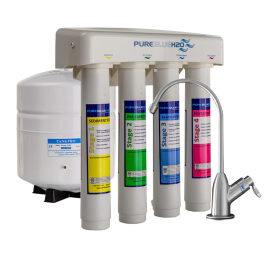
NOTE: See Product Data Sheet (PDS) for specifications. ADDITIONAL SYSTEM PERFORMANCE INFORMATION Non-potable Water Sources: Warning: Do not use with water that is microbiologically unsafe or of unknown quality without adequate disinfection before or after the system. Systems certified for cyst reduction may be used on disinfected water that may contain filterable cysts. - Page 13 SYSTEM MAINTENANCE (CONTINUED) Prefilter/Postfilter Note: The pre-filter and post-filters are replaceable sediment and activated carbon cartridges located in stages 1, 2 and 4. It is recommended to replace stage 1 and 2 every 6 months, stage 3 every 2-5 years and stage 4 annually. You may need to replace more often with high water usage or high sediment level.
-
Page 14: Filter Replacement
Filter Replacement Note: Place a bucket or pan under system to catch any water drips. Also, when replacing all four (4) stage filters, install new cartridges in reverse order turning to the right to secure: 4 – Post-Carbon Block Filter (replace every 1 year - Anually) 3 –... -
Page 15: Limited Warranty
Drain Flow Restrictor The restrictor is vital for proper operation of the RO membrane filter as it keeps water flowing through the membrane at the proper rate ensuring the water produced is the best quality. It is recommended the restrictor assembly be periodically inspected to be sure it is clean and unrestricted. If service is required on the drain flow assembly, disassemble and reassemble as outlined in Step Six on page 8. - Page 16 Pure lue H20, LLC 13813 Monroes Business Park Tampa, FL 33635 USA www.pureblueh2o.com (844) 787-3148 • (844) PURE-1-4-U...
Need help?
Do you have a question about the PB-TLRO4H50T and is the answer not in the manual?
Questions and answers
HOW MUCH AIR PRESSURE CAN I USE TO PUT INTO THE TANK SO THAT THE WATER COMES OUT FASTER
The maximum operating pressure recommended for the Pure Blue H20 PB-TLRO4H50T system is 100 psi. If pressure is below 40 psi, a permeate pump or booster pump may be considered to improve water flow.
This answer is automatically generated