
Related Manuals for Sunrise Medical Sterling Pearl


Summary of Contents for Sunrise Medical Sterling Pearl
- Page 1 Workshop Manual Workshop Manual Workshop Manual Workshop Manual Workshop Manual Pearl Scooter Pearl Scooter Pearl Scooter Pearl Scooter Pearl Scooter 4.5h 12.0h ST PS Sunrise Training and Education Programmes...
-
Page 2: Product Information
CERTIFICATION: CERTIFICATION: CERTIFICATION: Sunrise Medical is ISO 9001 certified, which ensures quality at all Sunrise Medical is ISO 9001 certified, which ensures quality at all Sunrise Medical is ISO 9001 certified, which ensures quality at all Sunrise Medical is ISO 9001 certified, which ensures quality at all Sunrise Medical is ISO 9001 certified, which ensures quality at all stages of the development and production of this scooter. -
Page 3: Table Of Contents
Table of Contents Chptr. Chptr. Chptr. Subject Subject Subject Page Page Page Chptr. Chptr. Subject Subject Page Page Health & Safety............1- 2 Tool Box..............3 Service Schedule............4 Technical Specifications..........5 Batteries Batteries Batteries Batteries Batteries Battery Box ..............6 - 7 Battery Charger ............ -
Page 4: Health & Safety
ST PS CHAPTER ONE HEALTH & SAFETY Sunrise Training and Education Programmes Health & Safety Batteries Batteries Batteries Batteries Batteries Good Working Practice Good Working Practice Good Working Practice Good Working Practice Good Working Practice All work carried out on batteries or battery Whilst working on powered mobility products, boxes should demand a degree of extra cau- it is essential to observe good working prac-... -
Page 5: Health & Safety
ST PS CHAPTER ONE HEALTH & SAFETY Sunrise Training and Education Programmes Battery Chargers Battery Chargers Battery Chargers Batteries continued Batteries continued Batteries continued Batteries continued Batteries continued Battery Chargers Battery Chargers · When the tops of batteries are exposed, Remember battery chargers are take extra care when working on or connected to Mains Electricity... -
Page 6: Tool Box
ST PS CHAPTER TWO TOOL BOX Sunrise Training and Education Programmes Tool Box Tool Box Tool Box Tool Box Tool Box Tool Box The following list of tools will enable any task Metric socket set. covered by this module, to be carried out Imperial socket set. -
Page 7: Service Schedule
CHAPTER THREE ANNUAL SERVICE & INSPECTION Annual Service & Inspection Genral Service Instruction for Mobility Vehicles Controller Controller Controller Controller Controller Chassis Plug Connections Plug Connections Plug Connections Plug Connections Plug Connections • • Condition, (Welded Joints etc.). External Connections External Connections External Connections External Connections... -
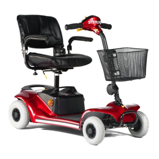
Page 8: Technical Specifications
40.5” / 103cm • scooter. Overall Width 22” / 56cm • Sunrise Medical reserve the right to make Min. Gnd - Seat Ht. 16.5”/ 42cm changes to such specifications when required, • without giving prior notice. Max. Gnd - Seat Ht. -
Page 9: Batteries Battery Box
ST PS CHAPTER FIVE BATTERIES Sunrise Training and Education Programmes Batteries Battery Box _ _ _ _ _ + + + + + Undo & remove the 12 fixing screws. Carefully lift the battery box lid away from the body. _ _ _ _ _ + + + + + The battery terminals are screw stud type. -
Page 10: Battery Box
ST PS CHAPTER FIVE BATTERIES Sunrise Training and Education Programmes Batteries Battery Box Use a 10mm spanner to disconnect the black Pull the two insulated spade terminal connec- charger inhibit lead. tors off the back of the circuit breaker. Use a 14mm spanner to carefully undo the Undo the two screws securing the charging circuit breaker nut. -
Page 11: Battery Charger
ST PS CHAPTER FIVE BATTERY CHARGER Sunrise Training and Education Programmes Batteries Battery Charger Open the charger socket cover to gain access Plug the charger output plug into the charging to the charging socket. socket on the battery box. Connect the charger mains plug to the power The battery box can be removed from the outlet and switch on. -
Page 12: Wheels Front Wheels
ST PS CHAPTER SIX WHEELS Sunrise Training and Education Programmes Wheels Front Wheels Use a thin knife blade or similar to carefully Remove the cap to expose the fixing stud. prise off the plastic hub cap. Steady the front of the scooter and remove the Use a X-head screw driver to loosen the stud wheel. -
Page 13: Rear Wheels
ST PS CHAPTER SIX WHEELS Sunrise Training and Education Programmes Wheels Rear Wheels Lift off the plastic cap to expose the bolt. Use a 13.0mm socket to undo the bolt. Withdraw the bolt, spacer, washer & spring Lift the wheel away from the rear axle taking washer. -
Page 14: Rear Drive Assembly
ST PS CHAPTER SEVEN REAR DRIVE ASSEMBLY Sunrise Training and Education Programmes Rear Drive Assy. Panels To change the rear drive body panel, first The rear drive assembly. seperate the rear drive from the main scooter body using the Gem-lock lever. Undo screws 1-4 and lift the handle off. -
Page 15: Motor Loom & Terminals
ST PS CHAPTER SEVEN REAR DRIVE ASSEMBLY Sunrise Training and Education Programmes Motor Loom & Terminals Cut any plastic tie-wraps, making a note of Unclip any metal cable tags to free the loom. their location for replacement later. Mark the top of the power terminals to aid re Disconnect the motor plug by pressing down on assembly and undo the four screws. -
Page 16: Transaxle & Fixings
ST PS CHAPTER SEVEN REAR DRIVE ASSEMBLY Sunrise Training and Education Programmes Transaxle & Fixings There are four fixing nuts securing the Use a 13.0mm socket on the nuts and a “x” Transaxle assembly. head screw driver on the right-hand studs. The left-hand side is a “U”... -
Page 17: Motor/Brushes
ST PS CHAPTER SEVEN REAR DRIVE ASSEMBLY Sunrise Training and Education Programmes Motor/Brushes Carefully lift the motor/brake assembly away Use a 6.00mm hex key or driver to undo the from the transaxle. four motor studs. Note that there is blue lock- tight used on the threads. -
Page 18: Motor/Brushes Test
ST PS CHAPTER SEVEN REAR DRIVE ASSEMBLY Sunrise Training and Education Programmes Motor/Brushes Test Hold the cap firmly when removing as it is Inspect the cap, (1), for burning, the lead, (2) under spring tension. Gently lift the motor for continuity, (see next) & carbon brush, (3) brush out of it’s housing. -
Page 19: Brake/Micro-Switch Test
ST PS CHAPTER SEVEN REAR DRIVE ASSEMBLY Sunrise Training and Education Programmes Brake/Micro-switch Test The brake micro-switch is secured with two To test the micro-switch, (mS), first set the small screws. The switch actuator is located at multimeter to the lowest RESISTANCE setting. the side of an operating cam which is con- As before, “1 1 1 1 1 or OC OC”... -
Page 20: Tiller & Footboard Removal
ST PS CHAPTER EIGHT TILLER & FOOTBOARD REMOVAL Sunrise Training and Education Programmes Front Basket Lift the basket off the bracket and away from The basket bracket has two hooks fixing the the tiller assembly basket. Use a X-head screw driver to undo the two With the bracket removed, loosen the four screws securing the bracket. -
Page 21: Tiller Adjuster
ST PS CHAPTER EIGHT TILLER & FOOTBOARD REMOVAL Sunrise Training and Education Programmes Tiller Adjuster Release the tiller lock. Locate the two mounting studs in the lowest position. Use a 4.00mm hex key and a 10.00mm spanner The tiller lock receiver and studs. to undo the two studs. -
Page 22: Lifting The Footboard
ST PS CHAPTER EIGHT TILLER & FOOTBOARD REMOVAL Sunrise Training and Education Programmes Lifting The Footboard To remove the tiller it is necessary to lift the Use a “X” head screw driver to undo both footboard. screws. There are two screws holding the rear of the footboard to the chassis. - Page 23 ST PS CHAPTER EIGHT TILLER & FOOTBOARD REMOVAL Sunrise Training and Education Programmes Lifting The Footbard Lift the back of the footboard clear of the Lift the footboard and rest it on the chassis to Gem-lock mechanism. access the loom & plugs. Locate the main tiller loom as shown.
-
Page 24: Lifting The Footboard
ST PS CHAPTER EIGHT TILLER & FOOTBOARD REMOVAL Sunrise Training and Education Programmes Lifting The Footboard Feed the loom & plug through the hole in the Remove the tiller assembly complete. front of the footboard. The blue power plug has to be disconnected To change the contacts/loom, first mark the before the footboard can be lifted clear of the terminals with a felt pen or similar. -
Page 25: Tiller Assembly
ST PS CHAPTER NINE TILLER ASSEMBLY Sunrise Training and Education Programmes Tiller Assembly Panels Remove the loom clip. Remove the tiller assembly as previously shown. Slide the panel down the shaft to access the Undo the two screws in the bottom of the tiller panel. -
Page 26: Tiller Assembly Pod
ST PS CHAPTER NINE TILLER ASSEMBLY Sunrise Training and Education Programmes Tiller Assembly Pod Carefully pull the loom through the tube and With the lower panel removed the pod fascia out through the top hole. is easily accessed. The tiller pod fascia can now be removed. Disconnect the white plug. -
Page 27: Tiller Assembly Key Switch
ST PS CHAPTER NINE TILLER ASSEMBLY Sunrise Training and Education Programmes Tiller Assembly Key Switch Cut the small tie wrap located near to the black Disconnect the black key switch plug. plug. Use long-nose pliers to undo the key switch Remove the nut and pull the key switch nut. -
Page 28: Tiller Assembly Wigwag
ST PS CHAPTER NINE TILLER ASSEMBLY Sunrise Training and Education Programmes Tiller Assembly WigWag Undo the two small screws securing the Remove the plastic thumb pads. potentiometer, (pot), to the tiller bar. Feed the wigwag assembly through the slot in The wigwag assembly removed. -
Page 29: Main Control Box
ST PS MAIN CONTROL BOX CHAPTER TEN Sunrise Training and Education Programmes Main Control Box To gain access to the main control box the Unplug the battery loom. footboard has to be lifted up as previously explained. Unplug the main loom. Unplug the motor/brake loom. -
Page 30: Main Frame
ST PS MAIN FRAME CHAPTER ELEVEN Sunrise Training and Education Programmes Main Frame Front Bumper The front bumper can be removed with the Position of the two grub screws, (shown with footboard still in place. Use a 3.00mm hex key the footboard removed). -
Page 31: Main Frame Steering Rods
ST PS CHAPTER ELEVEN MAIN FRAME Sunrise Training and Education Programmes Main Frame Steering Rods Use a 13.00mm spanner to hold the lower bolt Move the steering to access the steering link and a 13.00mm socket to undo the top nut. that joins with the steering head. - Page 32 ST PS CHAPTER ELEVEN MAIN FRAME Sunrise Training and Education Programmes Main Frame Steering Rods Carefully lift the steering link off the bolt. Remove the nut. Lift the small spacer off the bolt. Lift the large spacer of the bolt. Lift the washer off the bolt.
-
Page 33: Main Frame Steering Rods
ST PS CHAPTER ELEVEN MAIN FRAME Sunrise Training and Education Programmes Main Frame Steering Rods The steering rod on the left-hand side has the Use the 13.00mm spanner to hold the lower same nut and bolt connection as before. bolt & the 13.00mm socket to undo the nut. Remove the nut. -
Page 34: Main Frame Stub Axle
ST PS CHAPTER ELEVEN MAIN FRAME Sunrise Training and Education Programmes Main Frame Stub Axle The stub axle is secured by a 19.00mm nut. Use a 19.00mm socket to undo the nut. Remove the nut and the spacer. The stub axle is a tight fit. It may require tapping with a soft hammer whilst rotating the axle. -
Page 35: Steering Head, Bearings & Bump Stops
ST PS CHAPTER ELEVEN MAIN FRAME Sunrise Training and Education Programmes Main Frame Steering Head, Bearings & Bump Stops It is recommended to use an adjustable spanner The locking nut is on a fine thread, it is advis- to loosen the steering head locking nut. able to use fingers to remove it completely. -
Page 36: Steering Head, Bearings & Bump Stops
ST PS CHAPTER ELEVEN MAIN FRAME Sunrise Training and Education Programmes Main Frame Steering Head, Bearings & Bump Stops The front frame removed. When the stud thread is clear of the chassis, lift and pull the front frame clear. Gently lower the steering head. The rubber bump-stops can now be inspected or changed as required. -
Page 37: Gem-Lock
ST PS MAIN FRAME CHAPTER ELEVEN Sunrise Training and Education Programmes Main Frame Gem-Lock The Gem-lock assembly is located on the seat Use a 4.00mm hex key and a 10.00mm post. spanner, to undo the two securing bolts. Pull the Gem-lock assembly out of the Remove both of the bolts. -
Page 38: Power Output Terminals
ST PS CHAPTER ELEVEN MAIN FRAME Sunrise Training and Education Programmes Main Frame Power Output Terminals The power output terminals are fixed to a It is good working practice to mark the termi- bracket located just below the Gem-lock. nals to assist in re-assembly. Each block can be removed individually to Undo the four mounting screws. -
Page 39: Seat
ST PS SEAT CHAPTER TWELVE Sunrise Training and Education Programmes Seat Adjustments Armrests & Height The two armrest securing knobs are located Loosen each knob as required. under the seat, (1&2). Slide the armrest to the desired width or remove To adjust the seat height, firstly remove the completely. -
Page 40: Seat Covers
ST PS CHAPTER TWELVE SEAT Sunrise Training and Education Programmes Seat Covers Lift the cover off the backrest taking care not The backrest cover has two pop-stud fasteners to lose the foam insert. securing the fixing flap. Pull the pop-studs apart and fold the flap down. -
Page 41: Seat Positional Adjustment
ST PS CHAPTER TWELVE SEAT Sunrise Training and Education Programmes Seat Positional Adjustment Forwards Forwards Forwards Forwards Forwards Middle Middle Middle Middle Middle Back Back Back Back Back Forwards Forwards Forwards Forwards Forwards Middle Middle Middle Middle Middle Back Back Back Back Back...
Need help?
Do you have a question about the Sterling Pearl and is the answer not in the manual?
Questions and answers