Table of Contents
Advertisement
Quick Links
Advertisement
Table of Contents

Related Manuals for Humminbird Onix


Summary of Contents for Humminbird Onix
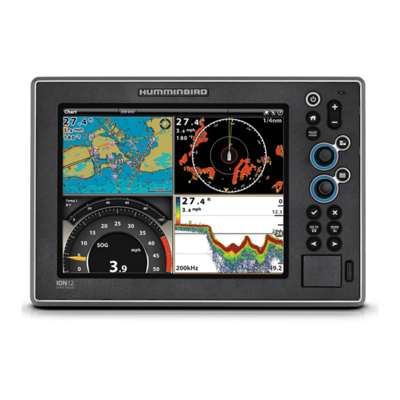
- Page 1 ONIX Operations Guide 532186-1EN_D PILOT STANDBY GO TO MARK...
-
Page 2: Warnings
Your Humminbird is designed for trouble-free use in even the harshest marine environment. In the unlikely event that your Humminbird does require repairs, we offer an exclusive Service Policy. For complete details, see the separate warranty card included with your unit. We encourage you to read this operations manual carefully in order to get the full benefit from all the features and applications of your Humminbird product. - Page 3 360 Imaging®, AUTOCHART®, AutoChart LIVE™, Cross Touch®, Down Imaging®, DualBeam PLUS™, Fish ID+™, Humminbird®, i-Pilot® Link™, ION™, LakeMaster®, ONIX®, Real Time Sonar™, RTS Window™, SI™, Side Imaging®, Structure ID™, SwitchFire®, WhiteLine™, X-Press™ Menu, and ZeroLine Map Card™ are trademarked by or registered trademarks of Johnson Outdoors Marine Electronics, Inc.
-
Page 4: Table Of Contents
Delete All Navigation Data .......108 ONIX Touch Screen and Keypad Import/Export Navigation Data . - Page 5 Set up a NMEA 2000 Network ......222 Set up your Humminbird Network ......231 Change the Network Name .
-
Page 6: Introduction
Web site at humminbird.com. Register and Update: As you build your Humminbird network, it is important to register your products and keep your software up to date. Visit our Web site at humminbird.com to set up an account, update control head and accessory software, and purchase additional equipment. -
Page 7: Getting Started
NOTE: When the ONIX and ION control head equipment and accessories are first installed, the Setup Guide provides the prompts to guide you through configuring the unit. The Setup Guide includes important steps to configure the control head with the equipment, including vessel dimensions, fuel data, transducer setup, map source selection, and offset menus. - Page 8 If you have connected an accessory to the control head, and the icon is not displaying in the system status bar, check the installation of the accessory and the cable connection to the control head. To change the NMEA 2000 network or multi-control head network sources, see Set up a NMEA 2000 Network and Set up your Humminbird Network. Getting Started...
- Page 9 Review GPS Reception In addition to the sensor icon in the status bar, you can also check the GPS reception status in the GPS tool. The GPS tool provides two ways to view the satellites communicating with the GPS Receiver. Yellow indicates that the satellite is being used to determine your current position.
- Page 10 You can also manually change which GPS receiver is the selected source for GPS (1) or GPS (2). To change the GPS sources, see Set up your Humminbird Network. GPS (1) provides position data, Speed over Ground (SOG), Course over Ground (COG), waypoints, routes, tracks, and navigation calculations to the control head.
- Page 11 1. Press the HOME key. Select Alarms. 2. Under Settings, select Alarms. If the control head is connected to the Humminbird network, select Local Alarms (control head only) or Networked Alarms (alarms shared across control heads). See Set up your Humminbird Network for more information.
- Page 12 See Sonar Overview: Sonar Alarms for details. Temp (High) or Temp (Low). To change the Temperature sources, see Installation Information: Temperature Set up your Humminbird Network. Low Fuel, Engine Temp, Oil Level, Coolant Level, Check Engine, etc. To change Engine and Fuel Engine sources, see Installation Information: Set up a NMEA 2000 Network.
-
Page 13: Touch Screen Overview
OUCH CREEN VERVIEW ROSS OUCH ODELS A summary of the touch screen actions are shown here. The touch screen actions are also determined by the view displayed on the screen. AP OR RESS AND INGER Select a View, Tool, Menu, or Icon: Tap the Switch to 2D or 3D View: With a 2D Chart selection once. -
Page 14: Onix Touch Screen And Keypad
Non-Tactile model, you will use the keypad exclusively for all your control head functions. Select a Tool, View, or Menu Touch Screen Keypad Select Open Tap to Select Scroll to See More Touch Screen Keypad Move Left or Right Swipe Left or Right ONIX Touch Screen and Keypad... - Page 15 Adjust a Menu Setting Touch Screen Keypad Press Turn Press and Hold Press and Hold OR Slide Activate the Cursor Touch Screen Keypad Move Zoom In, Zoom Out Touch Screen Keypad Zoom In Zoom Out Pinch In/Out ONIX Touch Screen and Keypad...
-
Page 16: Ion Touch Screen And Keypad
ION T OUCH CREEN AND EYPAD The Cross Touch feature allows you to use the touch screen and the keypad to select menus and start actions on the control head. Select a Tool, View, or Menu Touch Screen Keypad Select Open Tap to Select Scroll to See More... - Page 17 Adjust a Menu Setting Touch Screen Keypad Press Turn Press and Hold Press and Hold OR Slide Activate the Cursor Touch Screen Keypad Move Zoom In, Zoom Out Touch Screen Keypad Zoom In Zoom Out Pinch In/Out ION Touch Screen and Keypad...
-
Page 18: Onix Control Head
The functions for each key are described here. To apply the key functions, see each section of this manual. If you have a Cross Touch model, you can also use the touch screen to replace key functions. See ONIX Touch Screen and Keypad for more information. -
Page 19: Menu Key
For a closer view, press the ZOOM IN (+) key. For a wider view, press the ZOOM OUT (-) key. Press and hold the ZOOM OUT (–) key to Zoom out all the way. ONIX Control Head... -
Page 20: Ion Control Head
ION C ONTROL PILOT STANDBY GO TO MARK ION Key Functions The functions for each key are described here. To apply the key functions, see each section of this manual. You can also use the touch screen feature to replace key functions. See ION Touch Screen and Keypad for more information. ZOOM I (+)/ZOOM O (–) -
Page 21: Arrow Keys
ARROW PILOT ILOT TANDBY KEY KEYS STANDBY Use the PILOT/STANDBY key if there is an autopilot With a view displayed on-screen, press each arrow connected to the system. Press the PILOT/STANDBY key repeatedly until the Favorites view you want to key to open the Settings >... - Page 22 SD C USB P LOTS AND CAUTION! Before the control head software is updated or restored to system defaults, export your menu settings, radar settings, and navigation data (see Update Software). Load Maps SD C LOTS Insert an SD card with the label facing up. SD cards can be used to load additional charts, import/export navigation data, save screen snapshots, import/export menu settings, and more.
-
Page 23: The Home Screen
CREEN The Home screen is the main control center for your control head. Use the Home screen to access the control head settings, alarms, favorite views, and tools. The tools available on the Home screen are determined by the equipment attached to the control head network. - Page 24 Main Settings Select Settings to change general system settings such as the backlight, volume, units of measurement, and the time and date format. You can also use this menu to change the main settings for each application (Sonar, Chart, Radar, etc.). See each related section of this manual for details. Select Alarms to view the alarm log, turn on external alarms, mute alarm sounds, and set the alarms for the individual applications.
- Page 25 Tools Bar The Tools bar on the Home screen allows you to manage the control head operations. When you connect an accessory to the control head, a related tool may also be displayed here. Select Nav Data to manage your saved waypoints, routes, tracks, and groups. You can create new navigation data from this screen, edit your saved navigation data, or start navigation (see Manage your Navigation Data).
- Page 26 Select Fuel to review the fuel log for NMEA 2000 fuel sensors connected to the network. This tool provides refuel alerts and displays the fuel level in graphical form. See Set up a NMEA 2000 Network for details. Required Equipment: NMEA 2000 tank sensor and/or fuel flow rate sensor Select Tides to review information for the nearest tide station to your present position.
- Page 27 You can also designate a primary and secondary GPS source from this tool. See Getting Started, Installation Information, and Set up your Humminbird Network. Required Equipment: GPS receiver (internal or external) Select Files to update the software for the control head or connected accessories.
-
Page 28: The Menu System
YSTEM The ONIX and ION provide menu options that change with the application, on-screen view, and the operations mode. Open Settings The Settings tool provides main menu settings for the control head. 1. Press the HOME key. 2. Tap Settings. - Page 29 Open an X-Press Menu The X-Press Menu displays menu options for the on-screen view and operation mode (such as navigation). In a multi-pane view, the X-Press Menu options are determined by which pane is selected. See Views for more information. Open an X-Press Menu 1.
- Page 30 Change a Menu or Start an Action Use the following instructions to change a menu setting or start an action through the menu system. 1. Tap a menu category, or use the Joystick to select it. 2. Tap a menu option, or use the Joystick to select it. 3.
- Page 31 Tips for Changing a Menu This section describes the different types of menus in the menu system and how to change them using the touch screen or keypad. Action ( > ) Touch Screen Keypad Press On/Off Button Touch Screen Keypad Press Slider...
- Page 32 Tips for Using the On-Screen Keyboard Use the on-screen keyboard to rename the control head in the network, enter an Internet address, edit your navigation data, and more. arrows move name field the cursor right or left deletes a single character starts a new line...
- Page 33 Tips for Using the Status Bar The status bar is located at the top of the screen. It changes to match the on-screen view and operation mode. In the following illustrations, the information in the status bar corresponds with the Chart View displayed on-screen. Status Bar (Non-Tactile) displayed information changes to match the on-screen view and status sensor status...
-
Page 34: Views
IEWS The ONIX and ION have many options to display data on-screen, and the data can be displayed in a variety of ways. You can open a view from the Favorites bar or from the Views tool. You can also create a new view, edit views, and customize the Favorites bar. To add a view to the Favorites bar, or to remove a view, see Add or Remove the View from the Favorites Bar. - Page 35 Favorites bar Favorites bar See More: Swipe or use the Joystick Tap to Select Select Open Views...
- Page 36 Display a View from the Views Tool The Views tool includes the complete database of available views for your control head. Use the Views tool to create a new view and edit a view. You can also edit the Favorites bar from the Views tool. 1.
- Page 37 Views Tool (Cross Touch) return to selected group star = favorite Home screen close status bar groups available views Options: select to create a new view Tap to Select Select Open Views...
-
Page 38: Edit The On-Screen View
DIT THE CREEN You can edit a view from the Views tool or from the view that is displayed on the screen. When you edit a view from on-screen, the View Options menu provides additional editing options. Global: To appy changes to all views in the same category, turn on Global. To apply changes to the on-screen view exclusively, turn off... - Page 39 Display Data Overlays Digital readout data can be displayed as an overlay, and it can be displayed in the data bar. To turn on the data bar, see Display a Data Bar. Chart View with Data Overlays Displayed 1. With a View displayed on-screen, tap the view name in the status bar, or press the MENU key once.
- Page 40 Change the Data Boxes Use the following instructions to change the data boxes displayed in a data bar. NOTE: A data bar must be displayed to access the menu options in this section. See Display a Data Bar. 1. View Options Menu: With a view displayed on-screen, press the PANE key once. In a multi-pane view, press the PANE key repeatedly until the menu displays.
- Page 41 The number on the data label (Temp 1, Temp 2, Temp 3, etc.) corresponds with the source number. For more information about sources and networking, see Installation Information, Set up your NMEA 2000 Network, and Set up your Humminbird Network: Select Data Sources.
- Page 42 Label Name Description Data Type Fuel (#) Fuel Level The fuel level of the fuel source. Fuel The direction the boat is pointing, measured in degrees. Due to wind Heading and waves, the boat is often traveling in a slightly different direction Vessel than its heading.
-
Page 43: The View Options Menu
PTIONS The View Options menu provides options to edit the selected view. You can open the View Options menu from the on-screen view or from the Views tool on the Home screen. The menu options vary slightly. For example, if you open the View Options menu from an on- screen view, you can also edit the data bar from the menu. - Page 44 Open the View Options Menu from the Views Tool 1. Press the HOME key. 2. Select the Views tool. 3. Press and hold the view you want to edit. Use the Joystick to select a view. Press the MENU key. 4.
-
Page 45: Create A New View
REATE A Follow the instructions in this section to create a new view from a blank template. 1. Press the HOME key. 2. Select the Views tool. 3. Select New View. 4. See Edit the View Layout and Application to rename the view, edit the layout, add applications, display digital readouts, and more. - Page 46 Edit the View Layout and Application The Edit menu on the View Options menu allows you to change the type of data that is displayed in the view and how many panes are displayed. 1. Select Edit (or Edit View) from the View Options menu. 2.
- Page 47 Adding Applications to the Template applications tab preview window selected pane save applications selected application Tap to Select Select a Pane Select an Application Views...
- Page 48 Change the View Name (Views Tool) 1. Select Name from the View Options menu. 2. Use the on-screen keyboard to edit the view name. See The Menu System: Tips for Using the On-Screen Keyboard for more information. Add or Remove the View from the Favorites Bar 1.
-
Page 49: Set Up An Instrument View
NSTRUMENT The ONIX and ION control heads provide Instrument Views in a variety of combinations to display on-screen. You can use the standard Dashboard Instrument View or Engine Instrument View. You can also customize the gauges, data boxes, and ranges. - Page 50 Customize an Instrument View In an Instrument View, you can customize the gauges, data boxes, and ranges. You can change each item in the same way you change data boxes in a view. You can also set up warning limits for the selected data range. NOTE: The available changes and sources are determined by the selected gauge or data box.
-
Page 51: Chart Overview
The selected map source also influences the menu system. When you change the map source, the menu options for the Chart Views change, allowing you to add navigation data, shading, or alarms. 2D Chart View (Humminbird), Cross Touch X-Press Menu... -
Page 52: Map Source
(separate purchase required). Humminbird is the default map source, but you can change the map source at any time. When you install an SD card, the control head automatically chooses the best map to display. If you install more than one SD card, you can choose which map source you want to use. - Page 53 Change the Map Source When you install an SD card, the map source is changed automatically to match the SD card map source. You can also change the map source using the Settings tool. When you change the map source, the menu options for the Chart Views also change, allowing you to add navigation data, shading, alarms, and more.
- Page 54 Set up Humminbird When Humminbird is selected as the map source, you can use the system defaults, or you can set the menu settings to your preference. You can use the built-in Humminbird map, or you can install an SD chart card with additional Humminbird LakeMaster features.
- Page 55 2D Chart View (Humminbird) contour line land water level offset (brown) extends the land visually Chart Overview...
- Page 56 Set up Navionics When Navionics is selected as the map source, you can use the system defaults, or you can set the menu settings to your preference. You can use the built-in map, or you can install an SD chart card with additional features. 1.
- Page 57 2D Chart View (Navionics) dynamic tides/currents icon symbols chart boundary Chart Overview...
- Page 58 Set up C-MAP by Jeppesen When C-MAP by Jeppesen is selected as the map source, you can use the system defaults, or you can set the menu settings to your preference. You can use the built-in map, or you can install an SD chart card with additional features. 1.
- Page 59 2D Chart View (C-MAP by Jeppesen) dynamic depth shading current arrow symbols Chart Overview...
-
Page 60: Navigation Alarms Overview
NOTE: To turn on additional alarms that relate to your vessel and navigation, such as Lost Heading, Drift Alarm, Pitch, Roll, and more, select Home > Alarms > System and Home > Alarms > Vessel. Chart View with Alarm Overlays Displayed (Humminbird) off course... -
Page 61: Arrival Alarm
Off Course (XTE) Alarm Turn on Off Course (XTE) to receive an alert if the vessel has traveled outside the selected route. You can also set how far the vessel is allowed to move off course before the alarm is triggered. If the alarm is turned off, the Off Course limit can be displayed on the Chart View, but you won’t receive an alert if the vessel crosses it. - Page 62 Waypoint Avoidance Alarm Turn on Waypoint Avoidance to receive an alert if the vessel has crossed the Waypoint Avoidance Radius. If the alarm is turned off, the Waypoint Avoidance Radius can be set for a waypoint, and it will be displayed on the Chart View, but you won’t receive an alert if the radius is crossed.
- Page 63 Turn on the Alarm 1. Press the HOME key. 2. Select Alarms > Navigation. 3. Select Anti-Collision Alarm. Tap the on/off button, or press the ENTER key, to turn it on. Display the Anti-Collision Overlay When the overlay is turned off, the scan area is shown only when a danger is detected. When the overlay is turned on, the scan area is displayed at all times.
- Page 64 Guardian Alarm If C-MAP by Jeppesen is selected, and the Guardian Alarm is turned on, an alert will be provided based on potential dangers detected in the chart data ahead of the vessel, such as submerged obstructions, land, rocks, and more (Guardian Objects). You can also select Guardian Objects and how far in front of the vessel the area will be scanned based on distance or time.
-
Page 65: Man Overboard (Mob)
(MOB) VERBOARD As soon as you know that you have a man overboard (MOB), you should activate Man Overboard navigation to maximize the chances for a successful rescue. Man Overboard navigation marks the approximate point where the person went overboard and starts continuous navigation toward the Man Overboard waypoint. -
Page 66: Customize The Chart View
1. With a Chart View displayed on-screen, tap Chart in the status bar, or press the MENU key once. 2. Select Chart Options. 3. Select Preferences. Adjust the Depth Range and Colors NOTE: Humminbird must be selected as the map source to enable this feature. 1. From the Preferences menu, select Depth. depth colors contour interval... - Page 67 Set the Chart Orientation Use the Preferences menu to change the chart orientation. You can also select the Chart Orientation Menu on the status bar. 1. From the Preferences menu, select Orientation. 2. Select an orientation to apply to the chart. chart orientation setting preview window menu...
- Page 68 Set the Motion Mode Motion Mode controls how the chart moves on the view. 1. From the Preferences menu, select Motion Mode. 2. Select Relative or True. Relative The position of the vessel is fixed on the view and the chart moves with the vessel. True The chart is fixed and the vessel moves towards chart objects on the view.
- Page 69 Select Map Data When a Navionics chart or C-MAP by Jeppesen chart is installed and selected as the map source, you can set navaids, marine, and land icons to hidden or visible. The Depth menu option allows you to see shading on the map based on the set depth. NOTE: C-MAP by Jeppesen or Navionics must be selected as the map source to enable this feature.
-
Page 70: Change The Chart View Overlays
1. With a Chart View displayed on-screen, tap Chart in the status bar, or press the MENU key once. 2. Select Chart Options. 3. Select Overlays. 4. Use the touch screen or Joystick to select a menu and change a setting. (check mark = visible, blank = hidden). Chart View with Overlays Displayed (Humminbird) north indicator compass icon... -
Page 71: Chart And Radar
HART AND ADAR If a radar is connected to the control head network, the radar data can be displayed on the Chart View. To adjust the menu settings for the radar, see Radar Overview for more information. Display Radar on the Chart View 1. -
Page 72: Change The Chart Mode
HANGE THE HART Use the instructions in this section to switch the Chart View from 2D to 3D. C-MAP by Jeppesen also allows you to choose Perspective. NOTE: C-MAP by Jeppesen or Navionics must be selected as the map source to enable this feature. Change the Chart Mode Touch Screen Keypad... - Page 73 Switching to Perspective Mode (C-MAP by Jeppesen), Cross Touch The display options can be accessed from the status bar or the Chart X-Press Menu. Tap Twice Press the MENU key Select Chart Mode Chart Mode...
-
Page 74: Introduction To Navigation
There are many ways to start navigation or edit navigation data with your Humminbird control head. The instructions in this section review navigation features on the Chart View. To use navigation features from the Nav Data tool, see Manage your Navigation Data. -
Page 75: Navigation Menu Overview
This section is an overview of the menus available for navigation. The availability of menu options is determined by the navigation mode and your Humminbird model. To apply these functions, see Waypoints, Routes, Tracks, and Search. Navigation X-Press Menu (Cross Touch Models Only) The Navigation X-Press Menu allows you to open the following navigation menus: Mark, Go To, and Info. -
Page 76: Mark Menu
Mark Menu The Mark menu marks a waypoint at the selected location. You can also create a saved route or mark the vessel position. See Waypoints and Routes for more information about using this menu. Open the Mark Menu 1. Touch Screen: Select Mark from the Navigation X-Press Menu. Keypad: Press the MARK key. - Page 77 Go To Menu Options Select Quick Route to mark quick route points and start navigation. See Routes for more Quick Route information. Nav Data Open the Nav Data tool to select saved navigaton data and start navigation. Open the on-screen keyboard to enter a latitude/longitude position. Select Go To to start Lat/Long navigation to the position.
-
Page 78: Info Menu
Use the Info menu to start a proximity search. You can also set a trolling grid from this menu. If you are using Humminbird as the map source, you can search lake information. Navionics and C-MAP by Jeppesen also have additional search options. - Page 79 ENTER key to select the measurement start point. Move the Joystick to the second selected position, and press the ENTER key to mark the measurement end point. Select Lake List to search for lakes within a preset range. Humminbird must be selected Lake List as the map source.
-
Page 80: Cursor Menu
Cursor Menu (Cross Touch Models Only) The Cursor menu is another way to use the touch sceen and mark a waypoint, create a route, or start a search. The Cursor menu is only available in Cross Touch models with the 2D Chart View, Sonar Views, or Radar View displayed on-screen. Open the Cursor Menu 1. -
Page 81: Waypoints
AYPOINTS Waypoints are saved latitude/longitude positions. They mark a position of interest such as your favorite fishing area, structure, or marker buoy. The control head saves the position and allows you to edit the waypoint name, icon, and more (see Manage your Navigation Data). You can save 5,000 waypoints to the control head. Mark Waypoints Waypoints can be marked at the vessel position or cursor position. - Page 82 Marking a Waypoint at the Cursor Position The Mark menu opens when you press the MARK key or select Mark from the Navigation X-Press Menu. cursor MARK Move the Joystick Press the Press and Hold to Activate the Cursor MARK key Twice Waypoints...
- Page 83 Mark + Edit Waypoints (on the go) If you set the Mark Mode to Mark + Edit, you can edit a waypoint immediately when you mark it in the Chart View. See Manage your Navigation Data for more information. 1. Press the HOME key. 2.
- Page 84 Edit a Waypoint in the Chart View 1. Tap the waypoint icon to select it. Tap the Waypoint Name. Use the Joystick to move the cursor to a waypoint icon. Press the ENTER key. 2. Use the Waypoint Info menu to edit the waypoint name, icon, color, and more (see Manage your Navigation Data for more information).
- Page 85 NOTE: If the waypoint was marked at the cursor position, select Full Info > Edit Depth. Use the on-screen keyboard to enter a depth. If you turn on Depth Marker, the depth you enter will be displayed. Set the Waypoint Radius and Avoidance A radius can be set around a selected waypoint.
-
Page 86: Routes
OUTES Routes link two or more points together to create a path for navigation. A route represents your intended navigation and shows the shortest path from each data point to the next. The distance between each route point is a route leg. You can save 50 routes to the control head. - Page 87 Marking Route Points with the Touch Screen (Cross Touch) quick route active start navigation cancel undo last show vessel show cursor route point Tap to Mark Route Points Routes...
- Page 88 Starting Quick Route Navigation with the Keypad (Cross Touch) undo last quick route active start navigation cancel show vessel show cursor route point cursor marking a route point route point route leg GO TO Open Go To Menu Move Cursor Position Mark Route Points Start Navigation Routes...
- Page 89 Change Route Order During Navigation 1. During navigation, tap Chart in the status bar. Select Go To. Press the GO TO key. 2. Select one of the following menu options: Restart Course: Resets navigation to start from the current vessel position to the next point in the route. Next Point: Skips to the next point in the route.
- Page 90 Program a Position and Start Navigation Use the instructions in this section to enter a latitude/longitude position and start navigation to it. Start Navigation to a Latitude/Longitude Position 1. Tap Chart in the status bar. Select Go To. Press the GO TO key. 2.
- Page 91 Creating a Saved Route with the Keypad (Cross Touch) creating a saved route save route cancel undo last show vessel show cursor route point cursor marking a route point waypoint MARK Open Mark Menu Move Cursor Position Mark Route Point Save Routes...
- Page 92 Edit a Route in the Chart View 1. Tap the route to select it. Tap the Route Name. Use the Joystick to move the cursor to a route on the chart. Press the ENTER key. 2. Use the Route Info menu to edit the route name, color, and more (see Manage your Navigation Data for more information). 3.
-
Page 93: Search
4. To start navigation to your selection, press the GO TO key. Search for a Lake If Humminbird is selected as the map source, you can search for lakes in the area. 1. Tap Chart in the status bar. Select Info. - Page 94 Find the Nearest Navigation Data Use the Find Nearest menu to search for the closest waypoints, routes, and tracks. 1. Tap Chart in the status bar. Select Info. Press the ENTER key. 2. Select Find Nearest. 3. Select Waypoints, Routes, or Tracks. 4.
-
Page 95: Tracks
RACKS A track is a collection of track points that contains the vessel’s detailed position history at set intervals. The Current Track shows the position history since the control head was powered on. Record Track must be turned on to enable this feature (see Record a Track). - Page 96 Save the Current Track Use the following instructions to save the current track and start a new track. 1. Tap a track start point or end point. Tap the Track Name. Use the Joystick to move the cursor to a track start point or end point. Press the ENTER key. 2.
- Page 97 Edit a Track in the Chart View 1. Tap a track start point or end point. Tap the Track Name. Use the Joystick to move the cursor to a track start point or end point. Press the ENTER key. 2. Edit the track name, style, color, and more from the Track Info menu. 3.
-
Page 98: Manage Your Navigation Data
ANAGE YOUR AVIGATION Use the Nav Data tool to manage your saved waypoints, routes, tracks, and groups. You can edit your saved navigation data and start navigation from this tool. Open the Nav Data Tool 1. Press the HOME key. 2. -
Page 99: Manage Waypoints
Manage Waypoints Edit a Waypoint 1. Under Lists, select Waypoints. 2. Press and hold a waypoint. Select Info. Use the Joystick to select a waypoint. Press the ENTER key. 3. Edit the waypoint using the options in the Waypoint Info menu. To see the complete list of options to edit the waypoint, select Full Info. - Page 100 Change the Mark Mode for New Waypoints When you mark a waypoint, the control head assigns an alphanumeric name that can be edited from the Nav Data tool. Use these instructions to change how the control head marks a waypoint, allowing you to mark and edit waypoints as you go, or mark waypoints and edit them with your favorite settings.
- Page 101 Create Favorite Settings If you’ve selected Mark Favorites as the Mark Mode for waypoints, use the instructions in this section to preset your favorite icon, color, depth marker, default group, and whether the waypoint is visible or hidden. When you mark a waypoint, you will be given the menu options from your favorite settings to edit the waypoint.
-
Page 102: Manage Routes
Delete a Waypoint 1. Under Lists, select Waypoints. 2. Tap a waypoint or use the Joystick to select it. 3. Press the ENTER key. 4. Select Full Info. 5. Select Delete. Navigate to a Selected Waypoint 1. Under Lists, select Waypoints. 2. - Page 103 Selected Route with Route Points selected route routes selected route points selected route and preview window summary Delete a Route Point Touch Screen Keypad 1. Under Lists, select Routes. 1. Under Lists, select Routes. 2. Tap a route to open it and display its route points. 2.
-
Page 104: Manage Tracks
Delete a Route This menu option is not available while the selected route is being navigated. 1. Under Lists, select Routes. 2. Press and hold a route. Select Delete. 1. Use the Joystick to select a route. Press the ENTER key. 2. - Page 105 Record a Track When Record Track is turned on, the control head will save the current track. If you power off the control head and then power on the control head at a different position, there might be gaps in the track. If Record Track is turned off, the track will not be displayed on the Chart View, and the track will not be recorded or saved.
- Page 106 Edit a Saved Track 1. Under Lists, select Tracks. 2. Press and hold a track. Select Info. Use the Joystick to select a track. Press the ENTER key. 3. Edit the saved track using the options in the Track Info menu. To see the complete list of options to edit the track, select Full Info.
-
Page 107: Manage Groups
Manage Groups Use Groups to organize your navigation data (waypoints, routes, and tracks) in one set. Some anglers prefer to group their navigation data by trip, fish-type, body of water, or time of day. Default Group: Your navigation data is saved to My Data, the default group for your control head. You can create new groups and save new navigation data to them. -
Page 108: Delete All Navigation Data
2. Select a category. Follow the on-screen prompts to confirm the deletion. Import/Export Navigation Data The ONIX and ION allow you to export your waypoints, routes, and tracks, so you can view the data on your personal computer. You can also import your navigation data. -
Page 109: Autochart Live Overview
ZeroLine Map Card for unlimited mapping. ZeroLine Map Card: To purchase a ZeroLine Map Card and download the accessory guide, visit our Web site at humminbird.com. More Information: Visit our Web site for informational videos. -
Page 110: Prepare The Control Head For Mapping
| Set the Map Source AutoChart LIVE can be used when Humminbird LakeMaster or Navionics is set as the map source. When you install a map card, the map source is changed automatically to match the SD card map source. You can also change the map source using the Settings tool. - Page 111 7. Press and hold the EXIT key to close the menu system. 8. If there are additional control heads on your boat with a 2D transducer, confirm that they are not pinging while you are mapping. There should be only one 2D transducer pinging on your boat during the recording process. | Confirm Digital Depth and GPS Fix 1.
- Page 112 4. Select Recording Sources. Tap 2D Sonar, or press the ENTER key, to add a check mark to the box. 5. Press the EXIT key. 6. Select Start Recording. NOTE: For more information, see Sonar Recording. Also, visit our Web site at humminbird.com to purchase AutoChart PC and download the manual. AutoChart LIVE...
-
Page 113: Record Your Custom Map
2. R ECORD YOUR USTOM 1. Preparation: Before you start mapping for the day, confirm that the control head is set up as shown in the section Prepare the Control Head for Mapping. 2. With a Chart View displayed on-screen, tap Chart in the status bar, or press the MENU key once. 3. - Page 114 Collecting Data for your AutoChart LIVE Map depth boat icon depth map in progress contour lines (black lines) current track (red line) depth map scale 3. S ECORDING Use the instructions in this section to stop recording. Your map is automatically saved to the control head (internal) or to the ZeroLine Map Card if it is installed.
-
Page 115: Correct Data
ORRECT If you see an irregularity in the data (such as lost depth), it can be corrected. Recording must be turned off while you correct the data. 1. With a Chart View displayed on-screen, tap Chart in the status bar, or press the MENU key once. 2. -
Page 116: Display/Hide Your Custom Map
ISPLAY IDE YOUR USTOM The custom map can be displayed or hidden while you are recording or after the map is saved. You can also adjust the transparency. Display the Map 1. With a Chart View displayed on-screen, tap Chart in the status bar, or press the MENU key once. 2. -
Page 117: Adjust The Map Display Settings
DJUST THE ISPLAY ETTINGS The Map Options menu allows you to adjust the depth range, contour interval, water level offset, and map position. Some of the menu options in this section may be displayed in other parts of the menu system so that you can access them quickly. No matter where you make the change, the control head will update the setting across the system. - Page 118 Display or Adjust the Contour Interval You can display or hide the contour lines on the map, and you can adjust the slider to set the distance between each contour line. Contour Interval is also affected by the Water Level Offset setting. 1.
- Page 119 Add Settings with Chart Options You can also add adjustments to your custom map using the Chart Options menu. For example, if Humminbird is set as the map source, you can add Depth Colors, Shallow Water, etc. to your AutoChart LIVE map. See Customize the Chart View: Adjust the Depth Range and Colors for more information.
-
Page 120: Mosaic Overview
• To understand how 360 Imaging works, review the manual that is included with the transducer. When recording the Mosaic, you should have only one Side Imaging sonar source pinging on your boat. To select a Side Imaging sonar source or confirm pinging, see Set up your Humminbird Network: Select Sonar Sources. PEN THE OSAIC 1. - Page 121 Select a Save Location Use the following instructions to set up the Mosaic save location to an SD Card or USB stick (ION only). The Mosaic must be saved when you are finished recording or before you power off the control head, or the data will be lost. 1.
-
Page 122: Customize The Mosaic Display
USTOMIZE THE OSAIC ISPLAY You can display or hide a Mosaic, and you can adjust the Mosaic display settings while it is being recorded or when it is loaded on the Chart View. Display/Hide the Mosaic Overlay Use the instructions in this section to display or hide the Mosaic overlay. You can also adjust the transparency. 1. - Page 123 Change the Palette The Palette menu changes the colors used to display the Mosaic. The palette can be changed while a Mosaic is being recorded, or it can be applied to a saved Mosaic on the Chart View. 1. From the Mosaic menu, select Mosaic Options. 2.
- Page 124 Change the Mosaic Display Position The Mosaic will be displayed on-screen based on the Map Position setting. While you are recording a Mosaic, the Map Position should be set to Auto. 1. From the Map Options menu, select Map Position. 2.
- Page 125 Turn on/off Gain Correct Turn on Gain Correct to automatically tune the transducer signal and filter any clutter that may show up in the Mosaic data. 1. From the Mosaic Menu, select Mosaic Options. 2. Select Gain Correct. 3. Tap the on/off button, or press the ENTER key, to turn it on or off. Adjust the Sensitivity and Contrast The sensitivity and contrast can be adjusted while the Mosaic is being recorded or it can be adjusted when a saved Mosaic is loaded onto the Chart View.
- Page 126 Turn on/off Contour Mode Contour Mode controls how the water column is displayed in the Mosaic. The location of a target in the Mosaic is influenced by the Contour Mode setting. For more information, see Customize the Side Imaging View: Turn on/off Contour Mode. When Contour Mode turned off, the water column is displayed on the view.
-
Page 127: Autopilot Overview
UTOPILOT VERVIEW The Humminbird autopilot (SC 110) connects to the control head network. The Humminbird autopilot system requires a separate purchase. For additional autopilot products and equipment, visit our Web site at humminbird.com. SC 110 Humminbird Autopilot Nav Mode with Chartplotter Input... - Page 128 Send Navigation Data to the Autopilot When a route is started from the control head, it will communicate with the autopilot to tell it which way to turn to get on course. The Autopilot Navigation menu must be turned on to enable this feature on the control head. navigation menu Enable Autopilot Navigation...
-
Page 129: Radar Overview
ADAR VERVIEW The radar scanner must be connected to the control head to enable radar features. Some of the features also require a compass/heading sensor. NOTE: To configure the radar after installation or equipment repair, see Installation Information: Configure Radar. Radar View with Cursor Active (Cross Touch) Radar X-Press Menu orientation menu... -
Page 130: Radar Alarms
ADAR LARMS When an alarm is turned on, it will use the control head’s default setting to provide an alert, and you can also adjust the settings used to trigger an alarm. If you will be tracking targets with MARPA or AIS, see AIS and MARPA. Turn on Radar Alarms 1. - Page 131 Set the Guard Zone If you turned on the Guard Zone alarms in the Alarms tool, use this section to display the Guard Zone and adjust the settings that will trigger the alarm. The settings in this section are optional. You can turn on the Guard Zone alarms and receive alerts using the control head default settings.
- Page 132 Setting the Guard Zone Sector (Keypad) Radar X-Press Menu sensor status icons cursor marking 1st guard 2nd guard zone zone position position guard zone (shaded area) Select a Position Confirm Radar Alarms...
-
Page 133: Radar Transmission Settings
ADAR RANSMISSION ETTINGS The Radar Transmit menu can be accessed from the Power X-Press Menu, the Radar X-Press Menu, and the Radar tab in Settings. Start Transmission 1. Power On: Turn on the radar power source (breaker or switch). 2. Tap the top, right corner of the status bar. Press the POWER key. -
Page 134: Adjust The Transmission Range
DJUST THE RANSMISSION ANGE The scanner transmission range can be adjusted from the X-Press Menu or by pressing the +/- ZOOM keys. The range setting affects all the Radar Views in the control head. The control head will default to the largest chosen area from all of the Radar Views. Adjust the Range with the Keypad 1. -
Page 135: Customize The Radar View
USTOMIZE THE ADAR The settings in this section are optional. You can use the default settings for the Radar View, or you can customize it with your preferences. See Views for more information. PEN THE ADAR REFERENCES The Preferences menu allows you to set the Radar View orientation, vessel offset, and display colors. For more information about view preferences, see Views. - Page 136 Turn on/off Vessel Offset Vessel Offset allows you to see more of the view based on the speed of the vessel. Vessel Offset works with Auto Shift Speed. 1. From the Preferences menu, select Vessel Offset. 2. Select Off, On, or Auto Shift. Off...
-
Page 137: Change The Radar View Overlays
Radar Colors: The palettes in this menu are listed weakest return to strongest return, as follows: dark green (weak), light green (medium), orange (strong), red (strongest) Yellow dark green(weak), green (medium), yellow (strong) Green dark green (weak), green (medium), light green (strong) Magenta red (weak), crimson (medium), magenta (strong), pink (strongest) HANGE THE... - Page 138 Display Range Rings 1. From the Overlays menu, select Range Rings. 2. Tap the menu, or press the ENTER key, to add a check mark to the box. Display Vessel Icons The Vessel Overlay allows you to display the vessel icon with other visual information such as the heading line, COG (Course over Ground), Rate of Turn, and Drift Limit.
- Page 139 Display the Data Overlay Digital readout data can be displayed as an overlay, and it can be displayed in the data bar. To turn on the data bar, see Views: Display a Data Bar. For more information about data overlays, see Views. 1.
-
Page 140: Adjust Radar Signal Settings
DJUST ADAR IGNAL ETTINGS Use the settings in this section to filter the returns on the display or increase the amount of returns on the display. Adjust Gain Settings Use the Gain setting to adjust the sensitivity of the radar. Increase the gain to see more targets on the view, and decrease the gain to reduce the clutter caused by rain or snow. -
Page 141: Ebl/Vrm
EBL/VRM Use EBL (Electronic Bearing Range) and VRM (Variable Range Ring) to measure the distance and bearing between any two targets on the Radar View. The EBL and VRM can be set as a pair, and you can set two pairs. The marker is tied to the center of the vessel. As the vessel’s position and heading move, the EBL/VRM also moves. - Page 142 Edit an EBL/VRM 1. With a Radar View displayed on-screen, tap Radar in the status bar. Press the MENU key. 2. Select EBL/VRM. 3. Under EBL/VRM (1) or EBL/VRM (2), select Adjust. 4. Use the Joystick to move the cursor until it is positioned over the chosen EBL/VRM intersection. 5.
-
Page 143: Navigation In Radar View
AVIGATION IN ADAR You can mark waypoints and start navigation from the Radar View. See Introduction to Navigation for more features and information. NOTE: To display navigation data on the Radar View, see Change the Radar View Overlays: Display Navigation Data. Mark a Waypoint There are a variety of ways to mark a waypoint in the Radar View. - Page 144 Start Navigation There are a variety of ways to start navigation in the Radar View. The basic instructions are shown here. See Introduction to Navigation for more features and information. Start Quick Route Navigation Touch Screen Keypad 1. Tap Radar in the status bar. 1.
-
Page 145: Ais And Marpa
MARPA AIS and MARPA allow the control head to display targets on the Chart and Radar Views. While AIS and MARPA share many of the same menus and functions, some of the requirements and operations are different for each feature. AIS: Targets within the AIS VHF transmission range are displayed on Chart and Radar Views. - Page 146 Turn on MARPA Alarms For a MARPA target to be detected, the radar must be transmitting and a return must be identified as a target. The settings in this section are shared with Radar. 1. Press the HOME key. 2. Select Alarms. 3.
-
Page 147: Ais And Marpa Display Settings
MARPA D ISPLAY ETTINGS Display AIS and MARPA Targets Use the following instructions to display AIS or MARPA Targets on the Chart View or Radar View. NOTE: If Automatic AIS Tracking is turned on, but you do not see AIS targets on the chart and Radar Views, use these instructions to make sure targets are set to display in the Overlays menu. - Page 148 Set Target Display Settings In both AIS and MARPA, when a target is identified, it is displayed on the screen with an icon that indicates the target’s safety status. You can set defaults for how the targets will display on the screen. 1.
-
Page 149: Ais Overview
AIS O VERVIEW When an AIS is connected to the control head network, targets within the AIS VHF transmission range are displayed on the Chart and Radar Views. An AIS and compass/heading sensor are required to enable this feature. The AIS tracks up to 100 targets at once. The AIS also exchanges information with the targets, including vessel identification, position, course, and speed. - Page 150 AIS Filter Settings You can also control how many AIS targets are shown on the view by adjusting the filter settings. Turn on/off Range Filter If Range Filter is turned on, targets are displayed from your vessel to the distance you set. Targets outside of the range will not be displayed.
- Page 151 AIS Targets Each target is represented by an icon that indicates the vessel type. The color of the target icon is determined by the AIS Target Type shown on the AIS List. The target type shows its status with the following shapes and additional color details. For example, the Cargo Target appearance will change depending on its status, and whether it is moving or anchored, as shown in the following table: Underway Icon...
- Page 152 Track AIS Targets You can turn on tracking for all targets. You can also select individual targets and turn tracking on or off. Turn on/off Automatic AIS Tracking When Automatic AIS Tracking is turned on, all AIS targets are tracked within the equipment’s capabilities. When Automatic AIS tracking is turned off, all AIS targets are not tracked, but you can still track targets individually (see Track a Selected Target).
- Page 153 Start Navigation to a Selected Target Start navigation to a selected target using the following instructions. See Introduction to Navigation for more features and information. Start Navigation to a Selected Target Touch Screen Keypad 1. With a Chart View or Radar View displayed on-screen, 1.
- Page 154 Open the AIS Target List The AIS List is based on the last available transmission calculation and includes the targets’ name, MMSI (Maritime Mobile Service Identity, Distance, Bearing, SOG, and Class. The AIS List can be opened in the Targets tool, or it can be opened in the Chart and Radar Views.
- Page 155 Display the AIS Data for a Selected Target (Targets Tool) 1. From the Home screen, select the Targets tool. 2. Under Lists, select AIS. 3. Tap a target or use the Joystick to select it. Review the summary information in the dialog box (see the illustration AIS Target Data Received).
-
Page 156: Marpa Targets
MARPA T ARGETS Use MARPA to track targets on the Radar View. A compass/heading sensor must be attached to the control head network to enable MARPA, and the radar must be transmitting (see Radar Overview). If an AIS is connected, then AIS targets will also be displayed on the Radar View. - Page 157 Radar View with MARPA Targets Displayed (Cross Touch) orientation menu close cursor sensor status icons cursor over radar return tracked target distance and bearing to cursor position cursor position Press and Hold Move the Cursor to Press the Joystick a Radar Return a Radar Return to Acquire Target MARPA...
- Page 158 Cancel Tracking for a Selected Target 1. Select a target from the Radar View, Chart View, or Targets tool. 2. Tap the target name, or press the ENTER key. 3. Select Cancel Target. Cancel Tracking for all Targets (X-Press Menu) Use the instructions in this section to cancel tracking from the X-Press Menu.
- Page 159 Open the MARPA Target List Open the MARPA List from the Targets Tool 1. Press the HOME key. 2. Select the Targets tool. 3. Under Lists, select MARPA. Open the MARPA List from a View 1. With a Chart View or Radar View displayed on-screen, tap Chart or Radar in the status bar. Select Info. Press the ENTER key.
- Page 160 Display the MARPA Data for a Selected Target 1. With a Chart View or Radar View displayed on-screen, tap the target. Tap the target name. Use the Joystick to select a target. Press the ENTER key. The dialog box will display the ID, SOG (Speed over Ground), COG (Course over Ground), CPA (Closest Point of Approach), and TCPA (Time to Closest Point of Approach).
-
Page 161: Sonar Overview
A functioning transducer must be attached to the control head or selected as the transducer source on the network to enable sonar functions. To purchase transducers and black box sonar equipment, visit our Web site at humminbird.com. DualBeam PLUS Sonar The DualBeam PLUS sonar beams provide conical coverage directly below the boat. - Page 162 High Definition Side Imaging Sonar 86° 86° 455kHz 455kHz The HDSI transducer provides Side Imaging sonar, Down Imaging sonar, and DualBeam PLUS sonar on the control head. 45° 45° 800kHz 75° Side Imaging sonar uses two very precise sonar beams that are aimed at right angles to the 455kHz path of the boat.
-
Page 163: Sonar Setup
The selected transducer must be pinging to enable the views. When you connect a transducer to a black box sonar or to the ONIX control head, the transducer will be detected in the network automatically. The best sonar source will be chosen and start pinging automatically. -
Page 164: Sonar Alarms
ONAR ALARMS Before you start navigating and fishing with your control head, set up sonar alarms. A functioning transducer must be attached to the control head or selected as the transducer source on the network to enable all sonar functions. Turn on Sonar Alarms 1. -
Page 165: Sonar Overview
2D S ONAR VERVIEW (D PLUS TRANSDUCER REQUIRED As the boat moves, the unit charts the changes in depth on the display to create a profile of the bottom contour. The 2D Sonar View displays the sonar return intensity with different colors. Strong returns often result from rocky or hard bottoms (compacted sediment, rocks, fallen trees), while weaker returns often result from soft bottoms (sand, mud), vegetation, and small fish. -
Page 166: Customize The 2D Sonar View
2D S USTOMIZE THE ONAR The settings in this section are optional. You can use the default settings for the 2D Sonar View, or you can customize it with your preferences. See Views for more information. 2D S PEN THE ONAR REFERENCES The Preferences menu allows you to set the sonar mode, zoom mode, return palette, background color, bottom view, and... - Page 167 Set the Zoom Mode The Zoom Mode sets the zoom commands to magnify the full pane or the cursor selection. See Use Cursor and Zoom in Sonar Views to apply the zoom features. 1. From the Preferences menu, select Zoom Mode. 2.
- Page 168 Select Bottom Line to display the depth reading from the Depth Source as a line, either from Bottom Line the selected transducer or another digital depth source. See Set up your Humminbird Network for details about selecting sources. 2D Sonar...
- Page 169 Display the RTS Window The RTS Window plots the depth and intensity of a sonar return. It updates at the fastest rate possible for depth conditions and shows only the returns from the bottom, structure, and fish that are within the transducer beam. When you use the cursor to review sonar history, the sonar history will pause, but the RTS Window will continue to display sonar returns in real time.
- Page 170 2D Sonar View (Split Dual Mode) with RTS Window and Fish ID+ Turned On fish depth number fish icon fish depth (83 kHz number beam) fish icon (200 kHz beam) RTS Window set to A-Scope 2D Sonar...
-
Page 171: Change The 2D Sonar View Overlays
2D S HANGE THE ONAR VERLAYS Use the Overlays menu to display or hide information on the view. In the 2D Sonar View, you can display the following: depth lines, depth range, a color bar for the selected palette, temperature graph, beam frequency label, and data overlays. Digital readout data can be displayed as an overlay, and it can be displayed in the data bar. -
Page 172: Adjust 2D Sonar Display Settings
2D S DJUST ONAR ISPLAY ETTINGS The X-Press Menu provides menu options to adjust the sensitivity and range as you fish. You can also mark a particular depth and control how fast the sonar history scrolls across the screen. The menu options allow you to see more or less of the sonar returns from the transducer beams as you adjust each setting. - Page 173 Adjust Display Settings 1. With a 2D Sonar View displayed on-screen, tap Sonar (2D) in the status bar, or press the MENU key once. 2. Select Sensitivity, Surface Clutter, or Chart Speed. 3. Press and hold the slider, or turn the Rotary dial, to adjust the setting. Sensitivity controls how much detail is shown on the display and will adjust the sensitivity of all sonar frequencies.
- Page 174 If there are multiple beams available in a transducer, you can display individual frequencies on the 2D Sonar View. See Installation Information: Set up your Humminbird Network, Select Sonar Sources and Set up or Change Transducer Settings for details. 1. With a 2D Sonar View displayed on-screen, tap the frequency menu in the status bar.
-
Page 175: Side Imaging Overview
MAGING VERVIEW (S MAGING RANSDUCER EQUIRED Side Imaging beams “illuminate” the bottom contour, structure, and fish. The side beam coverage is very thin from front to back, yet very wide from top to bottom. The bottom composition determines the intensity of the sonar return, and upward slopes that face the transducer reflect sonar better than downward slopes that face away from the transducer. - Page 176 Side Imaging View, variations in the width of the water column show variations in the distance to the bottom as the vessel passes over. For Best Side Imaging Performance • Vessel Speed: 2 to 6 mph • Straight line navigation • Minimum turning time and wave turbulence Also, see humminbird.com for tutorials and Side Imaging videos. Side Imaging...
-
Page 177: Customize The Side Imaging View
USTOMIZE THE MAGING The settings in this section are optional. You can use the default settings for the view, or you can customize it with your preferences. See Views for more information. PEN THE MAGING REFERENCES The Preferences menu allows you to select a beam to display, set the zoom mode, return palette, and turn on Contour Mode and SI Navigation. - Page 178 Turn on/off Contour Mode Contour Mode controls how the water column is displayed in the Side Imaging Views. When Contour Mode turned off, the water column is displayed on the view. The location of a target on the display is based on the slant range to the target. When Contour Mode is turned on, the bottom is graphed at a constant point on the display, regardless of changes in depth.
-
Page 179: Change The Side Imaging View Overlays
HANGE THE MAGING VERLAYS Use the Overlays menu to display or hide information on the view. In the Side Imaging View, you can display the following: boat icon, range lines, range intervals, side label, frequency label, and data overlays. To turn on the data bar, see Views: Display a Data Bar. For more information about data overlays, see Views. -
Page 180: Adjust Side Imaging Display Settings
DJUST MAGING ISPLAY ETTINGS The X-Press Menu provides menu options to adjust the sensitivity, contrast, sharpness, and range as you fish. You can also mark a particular range, and you can control how fast the sonar history scrolls across the screen. The menu options allow you to see more or less of the sonar returns from the transducer beams as you adjust each setting. - Page 181 Set the Range Range controls how much of the water column is displayed on the view. 1. With a Side Imaging View displayed on-screen, tap Sonar (SI) in the status bar, or press the MENU key once. 2. Select Range. 3.
-
Page 182: Down Imaging Overview
MAGING VERVIEW (D MAGING RANSDUCER EQUIRED The images you see on the Down Imaging display are produced using sonar technology. Each time the unit pings, a strip of data representing all the echoes received by the transducer are put together on the display to form the image that you see. Like traditional 2D Sonar, the sonar history scrolls left across the screen. -
Page 183: Customize The Down Imaging View
USTOMIZE THE MAGING The settings in this section are optional. You can use the default settings for the view, or you can customize it with your preferences. See Views for more information. PEN THE MAGING REFERENCES The Preferences menu allows you to set the palette, zoom mode, and bottom line. For more information about view preferences, see Views. - Page 184 Add a check mark to Bottom Line to display the depth reading from the Depth Source as a line, either from the selected transducer or another digital depth source. See Set up your Humminbird Network for details about selecting sources.
-
Page 185: Change The Down Imaging View Overlays
HANGE THE MAGING VERLAYS Use the Overlays menu to display or hide information on the view. In the Down Imaging View, you can display the following: depth range, beam frequency label, and data overlays. Digital readout data can be displayed as an overlay, and it can be displayed in the data bar. -
Page 186: Adjust Down Imaging Display Settings
DJUST MAGING ISPLAY ETTINGS The X-Press Menu provides menu options to adjust the sensitivity and range as you fish. You can also mark a particular depth, and you can control how fast the sonar history scrolls across the screen. The menu options allow you to see more or less of the sonar returns from the transducer beams as you adjust each setting. - Page 187 Adjust Display Settings 1. With a Down Imaging View displayed on-screen, tap Sonar (DI) in the status bar, or press the MENU key once. 2. Select Sensitivity, Contrast, Chart Speed, or Sharpness. 3. Press and hold the slider, or turn the Rotary dial, to adjust the setting. Sensitivity controls how much detail is shown on the display and will adjust the sensitivity of all sonar frequencies.
-
Page 188: Use Cursor And Zoom In Sonar Views (2D, Si, Di)
URSOR AND OOM IN ONAR IEWS (2D, SI, DI) You can use the cursor in the 2D Sonar, Side Imaging, and Down Imaging Views. With the cursor activated, you can magnify sonar returns on the view to get a closer look. NOTE: To display the 2D Sonar View in Split Zoom mode, see Customize the 2D Sonar View: Change the Sonar Mode. - Page 189 Using Cursor Zoom Mode (Cross Touch, 2D Sonar View) show cursor exit cursor selection magnified magnification level location of cursor frequency in sonar label history (2D and DI only) Tap to Activate Pinch out to Magnify Move the Joystick Press the + ZOOM key to the Cursor the Selection to Activate the Cursor...
-
Page 190: Navigation In Sonar Views (2D, Si, Di)
AVIGATION IN ONAR IEWS (2D, SI, DI) To mark waypoints and start navigation, the control head must have a GPS fix from a connected or internal GPS receiver. The navigation menus can be accessed from the X-Press Menu, touch screen, and the keypad. Mark a Waypoint You can mark a waypoint on the Sonar Views using the keypad or touch screen (Cross Touch models only). - Page 191 Using the Touch Screen to Mark a Waypoint (Cross Touch, 2D Sonar View) show cursor exit cursor cursor menu cursor distance and bearing to cursor position cursor position Press and Hold Sonar & Navigation...
- Page 192 Navigate to a Position Use the instructions in this section to start navigation to a position in the Sonar Views. See Introduction to Navigation for more information about these features. Start Navigation Touch Screen Keypad 1. Press and hold a position on the Sonar View. 1.
-
Page 193: Sonar Recording
ONAR ECORDING Use the Sonar Recording menu to record active sonar information. Sonar recordings are saved to an installed SD card, and you can play your saved sonar recordings from the Recordings tool. When the recording is played back, the views that were active during the recording are available. -
Page 194: Images Tool
The Images tool displays the screen snapshots saved to the control head or to the installed SD cards or USB sticks (ION only). You can edit, rename, copy, and delete a screen snapshot. You can also view your saved screen snapshots (JPG files) as a slide show. NOTE: The USB ports are not available on the ONIX. Take a Screen Snapshot Use the screen snapshot feature to take a picture of the on-screen view. - Page 195 Sort Screen Snapshots 1. From the Images tool, select Settings. 2. Select Sort Options. 3. Select a sort option to sort by Name, Date, or File Type. To view the images from newest to oldest, select Reverse Order. Tap the on/off button, or press the ENTER key, to turn it on. Screen Snapshot Settings Screen snapshots are automatically saved to the control head as JPG files.
- Page 196 Create a Waypoint with Screen Snapshot If you turn on Create Waypoint in the Images tool, each time a screen snapshot is taken, the waypoint position will be saved. 1. Press the HOME key. 2. Select the Images tool. 3. Select Settings. 4.
- Page 197 Display Screen Snapshots and Slideshow When you select a saved screen snapshot (JPG file) from the Images tool, you can display it in full-screen using the touch screen or keypad. Using the Touch Screen with a Saved Screen Snapshot (Cross Touch) close start slideshow...
- Page 198 Set up the Slideshow Screen snapshots and pictures from your camera’s SD card can be displayed in a slideshow. You can use the control head default settings to play the slide show, or you can set the slideshow to loop or shuffle. 1.
- Page 199 Edit Screen Snapshots The Images Options menu allows you to edit the name and review the file information for the selected screen snapshot. You can also copy screen snapshots to another save location or delete them. Change a Screen Snapshot Name 1.
-
Page 200: Video View
If you connect an IP Video Camera to the control head network, you can watch the streamed video from a full-screen view or multi- pane view. The ION control head allows you to display up to four video camera sources. The ONIX control head displays video from one camera source. - Page 201 Press the MENU key once. Display Cameras on the Video View The ION control head allows you to display up to four video camera sources. The ONIX control head displays video from one camera source. Select a Camera Source to Display 1.
- Page 202 Change the Video Display Settings Adjust the Video Display Settings The control head allows you to adjust the brightness, contrast, and saturation from the Video X-Press Menu. 1. From the Video X-Press Menu, select Brightness, Contrast, Saturation, or Sharpness. 2. Press and hold the slider, or turn the Rotary dial, to adjust each setting. Display the Data Overlay 1.
-
Page 203: Internet Tool
NTERNET (ION ONLY Select the Internet tool to open the Browser and surf the Web. This feature is only available on the ION control head with an external wireless antenna and an Internet connection. To set up a Wi-Fi connection, see Installation Information: Set up Wireless. Open the Internet Tool 1. - Page 204 Open the Internet X-Press Menu The X-Press Menu on the Internet tool provides access to bookmarks, browsing history, and Internet settings. Open the Internet X-Press Menu 1. With the Internet tool displayed on-screen, tap Internet in the status bar. Press the MENU key once. Open a New Tab You can open five tabs in the Internet tool.
- Page 205 Set the Home Page 1. Tap the address bar, and use the on-screen keyboard to type an Internet address. 2. Tap Internet in the status bar, or press the MENU key once. 3. Select Settings. 4. Select Assign Home Page. Change the Search Engine 1.
-
Page 206: Installation Information
This section includes information that may be required to connect new equipment or a new accessory to the control head. There are several configurations available for your ONIX and ION control head. You can network control heads, connect accessories to an Ethernet network, connect to a NMEA 2000 network, and add transducers to your system through black box sonar. -
Page 207: Set Up Wireless
ONLY Use the Wireless tool to access a Wi-Fi network and use the Internet on your ION control head. The Wireless antenna requires a separate purchase. Visit our Web site at humminbird.com for details. Open the Wireless Tool 1. Press the HOME key. - Page 208 Selecting a Wi-Fi Network signal known network strength locked sort bar turn on Wi-Fi selected network network list Sort Lists 1. Press the EXIT key to select the sort bar. Tap a column name, or move the Joystick and press it on a column name. The first tap/Joystick press will sort the column low to high or A to Z.
- Page 209 Automatically Connect to a Network Use Auto-Connect to specify a preferred network. When Auto-Connect is selected with a check mark, the control head will connect to the selected network first when Wi-Fi is turned on. 1. Turn on Wi-Fi. 2. Tap the network name, or use the Joystick to select it. 3.
- Page 210 Turn on Wi-Fi Notifications To receive an alert when a new network has been detected, add a check mark to Notifications. The notification is for new networks only. If the network detects a previously-known network, it will connect to it without notification. Receive Notifications for Available Networks 1.
-
Page 211: Set Up Or Change Transducer Settings (Optional)
OPTIONAL When you connect a transducer to a black box sonar or to the ONIX control head, the transducer will be detected in the network automatically. The best transducer source will be chosen and start pinging automatically. If you connect an accessory transducer to the network, the unit will recognize the new transducer. - Page 212 See the illustrations for examples. NOTE: The capabilities of your sonar model are shown on the packaging, or you can find your transducer on our Web site at humminbird.com. 7. Frequencies: Select the Frequency Menu under each checked sonar capability.
- Page 213 If the selected transducer (sonar source) includes more than one beam, you can select which beam will be displayed in the sonar view. The beams selected in this menu affect all units that are sharing the sonar source. See Set up your Humminbird Network: Select Sonar Sources for details.
-
Page 214: Configure Radar (Installation And Repair Only)
WARNING! The features in this section affect the performance of the radar and should only be adjusted by a qualified radar technician. CAUTION! Before the radar settings are adjusted, or before the ONIX and ION software are updated or restored to system defaults, export the radar installation settings. See Export Radar Installation Settings. - Page 215 Main Bang Suppression Set the Main Bang Suppression to create a range around the vessel, or the center of the radar pane, where the radar signal will be suppressed. The targets in this range will not be seen. WARNING! Targets in the Main Bang Suppression Range are not displayed on the Radar View. 1.
- Page 216 Setting the Sector Blanking Range sector start sector end sector start and sector end menus Set the Sector Blanking Range Sector Blanking sets an area where the radar will not scan. This setting is useful for preventing reflections or false echoes from displaying on the Radar View;...
- Page 217 WARNING! Humminbird is not responsible for the loss of data files (waypoints, routes, tracks, groups, snapshots, recordings, etc.) that may occur due to direct or indirect damage to the unit’s hardware or software. It is important to back up your control head’s data files periodically.
-
Page 218: Configure The Control Head
When the ONIX and ION control head equipment and accessories are installed, the Setup Guide provides the prompts to guide you through configuring the unit. When you attach new hardware to the control head after it has been configured, the unit will detect the new hardware and provide additional prompts to add the equipment to the system. - Page 219 Sensor Port Connections (GPS, RS-232, NMEA 0183) When equipment is connected to the control head, the equipment and its data will be detected automatically. You can also manually select data, set the data offset, baud rate, and NMEA output sentences from the Sensor Port submenus. The available menus are determined by the attached equipment.
-
Page 220: Nmea 0183
NMEA 0183 Message Description Input Output • Waypoint Arrival Alarm • Heading/Track Controller (Autopilot) Sentence “B” Bearing-Origin to Destination • • Bearing & Distance to Waypoint - Great Circle Bearing & Distance to Waypoint - Rhumb Line • • • Depth Below Transducer Depth •... - Page 221 7. Under AutoPilot, select APB. Tap the check box, or press the ENTER key, to add a check mark to it. 8. To enable all modes of the SC 110 with the ONIX or ION control head, select the NMEA Output sentences as shown in the following table.
-
Page 222: Set Up Anmea 2000 Network
When equipment is connected to the control head, the equipment and its data will be detected automatically. You can also manually select equipment and set the data offset. The available menus are determined by the attached equipment. NOTE: Humminbird recommends that the NMEA 2000 network be installed by a certified NMEA 2000 technician. See NMEA.org for details. - Page 223 NMEA 2000 Network Devices Selected Manually Turn off Auto-Select selected device devices detected but not selected NMEA 2000 Network Devices Selected Automatically Turn on Auto-Select devices detected and selected on the NMEA 2000 network NMEA 2000 Setup...
- Page 224 Set NMEA 2000 Data Offsets 1. From the NMEA 2000 Sensor port menu, select Data Offsets. 2. Select a device. 3. Tap the on/off slider, or press the ENTER key, to turn it off. 4. Press and hold the slider, or press and hold the ENTER key, to set the offset amount. NMEA 2000 Data Offset Turn off the slider to manually adjust...
- Page 225 NMEA 2000 Messages (PGN) The following NMEA 2000 input/output messages are available when NMEA 2000 is turned on and the related NMEA 2000 equipment is detected and selected as a source. Message (PGN) Description Input Output 059392 ISO Acknowledgement • •...
- Page 226 NMEA 2000 AIS Messages (PGN) The following NMEA 2000 input/output messages are available when NMEA 2000 is turned on and an AIS is detected and selected as a source on the NMEA 2000 network. Message (PGN) Description Input Output 129038 Class A Position Report •...
- Page 227 Engine 1 Source Auto-Configured Engine (1) is selected When Auto- Configure is turned on, the control head assigns numbers to each engine automatically. Instance 0 = Engine 1 Source Change the Engine Source Assignments The instructions in this section are optional and allow you to change which engine is assigned as the Engine 1, Engine 2, or Engine 3 source in the control head.
- Page 228 Set up Fuel Tanks The Setup Guide provides prompts to set up the fuel tanks in the system, and it assigns a source number to each fuel tank. If a NMEA 2000 fuel tank sensor and a fuel flow rate sensor are installed, the control head can display fuel levels automatically. If only a fuel flow rate sensor is installed, you need to set up the fuel tanks manually to manage fuel levels.
- Page 229 Setting up Fuel Tanks Manually settings select Manual select Fuel Capacity to enter data manually Displaying the Fuel Tool Open the Fuel Tool 1. Press the HOME key. 2. Select the Fuel tool. Refill the Tank(s) The menu options in this section are determined by the Fuel Management Mode (Manual or Automatic). See Set the Fuel Tank Capacity for more information.
- Page 230 Change the Fuel Tank or Fuel Flow Source Assignments The instructions in this section are optional and allow you to change which fuel tank is assigned as the Tank 1, Tank 2, or Tank 3 source in the control head. You can also use these instructions to change the fuel flow rate Sensors (Fuel Flow) assignments. The menu options are determined by the type of sensors installed.
-
Page 231: Set Up Your Humminbird Network
UMMINBIRD ETWORK When the Humminbird network is fully installed, configure the network so the control heads and equipment are synchronized across the network. Depending on your network configuration, your options may include sources from remote control head(s), RS-232, NMEA 0183, Ethernet, and NMEA 2000. - Page 232 When a transducer is first connected to the control head or network (through black box sonar or additional Humminbird control heads), it will be detected by all control heads in the network. The ONIX control head selects the transducer connected to it as the primary sonar source.
- Page 233 The transducer you select on the Down Imaging tab will provide the data for the Down Imaging Views and related digital readouts. The transducer you select on the Side Imaging tab will provide the data for the Side Imaging Views and related digital readouts. Humminbird Network Setup...
- Page 234 2D tab, Down Imaging sources will only be displayed on the Down Imaging tab, etc. NOTE: If you have installed an accessory transducer, and it is not displayed in the transducer list, see Installation Information: Set up or Change Transducer Settings. Humminbird Network Setup...
- Page 235 Auto, 83/200 kHz, or 50/200 kHz. Then, you can select individual frequencies from the 2D Sonar View (see Select Frequencies). Selecting 2D Sonar Beams sonar Beam Select menu for 2D Sonar Humminbird Network Setup...
- Page 236 Select 800 kHz for faster pinging in shallow water. Side Imaging Beam Select Options 455 kHz 455 kHz is the default selection. Select 455 kHz for greater bottom coverage in deep water. 800 kHz Select 800 kHz for faster pinging in shallow water. Humminbird Network Setup...
- Page 237 NOTE: If the control head is using a sonar source with only one beam frequency, the frequencies menu will not offer additional options. See Set up or Change Transducer Settings for details. Sonar View (Cross Touch, 2D Sonar) frequency menu Humminbird Network Setup...
- Page 238 You can also manually change which GPS receiver is the selected source for GPS (1) or GPS (2). For example, if you’ve connected an external GPS receiver to the ONIX control head, you can assign it to GPS (1), so the control head will use it as the primary source (instead of the internal GPS receiver).
-
Page 239: Change The Network Name
1. Press the HOME key. 2. Select Settings. 3. Select Network. 4. Select Network Info. 5. Select Rename Network. Use the on-screen keyboard to change the control head name. 6. Select Save. Humminbird Network Setup... - Page 240 In the illustration above, see Information about the Selected Source. The Temp 1 digital readout data is The Temp 2 digital readout data is provided by the Temp (1) source. provided by the Temp (2) source. Humminbird Network Setup...
-
Page 241: Manage Your Control Head
ANAGE YOUR ONTROL Many of the control head settings can be accessed from the Settings tool (General Menu) or from the Power X-Press Menu in the status bar. Open the Settings Tool 1. Press the HOME key. 2. Select Settings. 3. - Page 242 WARNING! Humminbird is not responsible for the loss of data files (waypoints, routes, tracks, groups, snapshots, recordings, etc.) that may occur due to direct or indirect damage to the unit’s hardware or software. It is important to back up your control head’s data files periodically.
-
Page 243: Update Software
3 minutes to update. Supplies: In addition to your Humminbird equipment, you will need a PC with Internet access and a blank SD card. If you have an ION, you can use a USB stick for the instructions in this guide. - Page 244 1. Install the SD card into the PC card slot. 2. Go to humminbird.com, and select My Humminbird to sign in to your account. 3. Select the My Equipment tab. The available software updates are listed as Downloads under each registered product.
- Page 245 Update Software Automatically 1. Press the POWER key. Follow the on-screen prompts to start normal mode on the control head. 2. Install the SD card with the software file(s) into the control head card slot. 3. A dialog box will display to start the software update. To start the control head software update, select Install.
- Page 246 | Update Accessories Accessory software is updated from the Files tool, and the process is similar to updating the control head software. It is important to review the following tips: • Update the control head and accessories in the order they appear on the software update list in the Files Tool. Sonar Black Boxes (SM1000/2000/3000) and Ethernet Switches must be updated individually on the software update list.
-
Page 247: Statements And Acknowledgements
TATEMENTS AND CKNOWLEDGEMENTS ENVIRONMENTAL COMPLIANCE STATEMENT: It is the intention of Johnson Outdoors Marine Electronics, Inc. to be a responsible corporate citizen, operating in compliance with known and applicable environmental regulations, and a good neighbor in the communities where we make or sell our products. - Page 248 Eufaula, AL 36027 *NOTE: A copy of the libxml++ software is not required to upgrade your fishing system. The Humminbird application software and control head include a separate service warranty. Please see humminbird.com and the separate warranty card included with your unit for details.
- Page 249 Eufaula, AL 36027 *NOTE: A copy of the Linux operating system is not required to upgrade your fishing system. The Humminbird application software and control head include a separate service warranty. Please see humminbird.com and the separate warranty card included with your unit for details.
- Page 250 Navionics WARNINGS: The electronic chart is an aid to navigation designed to facilitate the use of authorized government charts, not to replace them. Only official government charts and notices to mariners contain all information needed for the safety of navigation, and as always, the captain is responsible for their prudent use.
- Page 251 Eufaula, AL 36027 *NOTE: A copy of the Qt software is not required to upgrade your fishing system. The Humminbird application software and control head include a separate service warranty. Please see humminbird.com and the separate warranty card included with your unit for details.
-
Page 252: Contact Humminbird
ONTACT UMMINBIRD Contact Humminbird Customer Service in any of the following ways: Web site: humminbird.com E-mail: service@humminbird.com Telephone: 1-800-633-1468 Direct Shipping: Humminbird Service Department 678 Humminbird Lane Eufaula, AL 36027 USA Hours of Operation: Monday - Friday 8:00 a.m. to 4:30 p.m. (Central Standard Time) Social Media Resources: Facebook.com/HumminbirdElectronics...
Need help?
Do you have a question about the Onix and is the answer not in the manual?
Questions and answers