Samsung RB215LASH Service Manual
Hide thumbs
Also See for RB215LASH:
- Service manual (85 pages) ,
- Owner's manual (25 pages) ,
- Owner's manual (24 pages)

Related Manuals for Samsung RB215LASH


Summary of Contents for Samsung RB215LASH
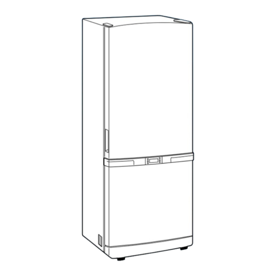
- Page 1 REFRIGERATOR RB215LASH RB215LABP REFRIGERATOR PRODUCT FEATURE ● Reversible Door ● Auto Ice-Maker ● Freezer Wire Box SAM0075...
-
Page 2: Important Safety Notice
SAMSUNG ELECTRONICS AMERICA, INC. Technical Service Guide Copyright 2005 All rights reserved. This service guide may not be reproduced in whole or in part in any form without written permission from the SAMSUNG ELECTRONICS Company. -
Page 3: Table Of Contents
Contents 1. INSTALLATION 2. NOMENCLATURE 3. PRODUCT SPECIFICATIONS 4. ELECTRICAL PART SPECIFICATIONS & STANDARD 5. INTERIOR VIEWS AND DIMENSIONS 6. REFRIGERATION CYCLE AND COOL AIR CIRCULATION ROUTE 7. MECHANICAL DISASSEMBLY 8. REVERSIBLE THE DOOR SWING 9. INSTALLATION OF THE WATER LINE 10. -
Page 4: Installation
1. INSTALLATION 1) To protect refrigerator in movement Use padded hand truck from side only. 2) Remove all protective tape and pad from the fridge. Connect power cord. Adjust the clearance between the doors. 3) Temperature controls and preset in the factory for recommended settings. -
Page 5: Product Specifications
3. PRODUCT SPECIFICATIONS RB215LASH, RB215LABP Model Type BMF 2 Door Temperature control Electronic control Total 20.4 Net Capacity Freezer 13.9 Fridge Net dimension 32.3 28.3 69.9 Cabinet insulation CYCLO-PENTANE Foam Door insulation CYCLO-PENTANE Cabinet A.B.S Liner Door A.B.S Net weight(Ib) 4. - Page 6 ELECTRICAL PART SPECIFICATIONS & STANDARD ITEM STANDARD Type Temperature Selection ON( ) OFF( ) –14 –12.0 –16.0 Freezer F-Sensor –2 –4 Type Temperature Selection ON( ) OFF( ) Fridge R-Sensor First Defrost Cycle 10min (Concurrent Defrost of F and R) Defrosting Min.
-
Page 7: Interior Views And Dimensions
5. Interior Views and Dimensions 5-1) Shelves and Bins • Deli drawer • Door Bin Pull it out to disassemble. Push it up and slide it out to disassemble. Light • • • • Gallon Bin • Glass Shelf • Pull it out until its stop •... - Page 8 Interior Views and Dimensions 5-2) Dimensions of Fridge (Inches) MODEL RB215 26.3 30.3 59.8...
-
Page 9: Refrigeration Cycle And Cool Air Circulation Route
6. Refrigeration Cycle and Cool Air Circulation Route 6-1) Refrigerant Route in Refrigeration cycle Compressor Sub condenser Cluster pipe Hot pipe Dryer Capillary tube R-Evaporator F-Evaporator Accumulator Suction pipe Compressor... - Page 10 Refrigeration Cycle and Cool Air Circulation Route 6-2) Cool Air Circulation...
-
Page 11: Mechanical Disassembly
7. Mechanical Disassembly Fridge Disassembly Control Panel Fridge Light Freezer Light Evaporator Cover in the Fridge Evaporator Cover in the Freezer Evaporator in the Freezer Evaporator in the Fridge Machine Compartment Electric Box... -
Page 12: Control Panel
Mechanical Disassembly Control Panel 1. Remove the screws. 2. Pull out the control panel. 3. Disconnect the wire connector. -
Page 13: Fridge Light
Mechanical Disassembly Always unplug the power cord before replacing the fridge lamp. There is the danger of electric shock. Warning Fridge Light Freezer Light 1. Remove the cover by pressing the bottom tab. 1. Remove the screw. 2. Remove the lamp cover by unlocking the tabs and pulling the cover down. -
Page 14: Evaporator Cover In The Fridge
Mechanical Disassembly Evaporator Cover in the Fridge 6. Disconnect the wire connector. 1. Remove all shelves and drawers from the fridge. 2. Pull out the screw caps with a small flat-blade screwdriver. 3. Remove 6 Phillps screws from the cover. Ductwork of the evaporator fan assembly. -
Page 15: Evaporator Cover In The Freezer
Mechanical Disassembly Evaporator Cover in Freezer 5. Disconnect wire connector from the top-left 1. Remove all drawers from the freezer. corner. 2. Remove screws (2) from the support rail. 6. Remove 2 screws from the rear cover of the freezer evaporator and unlock the tabs to remove it. -
Page 16: Evaporator In The Freezer
Mechanical Disassembly Evaporator in Fridge Evaporator in Freezer Evaporator is located in the bottom of fridge. Evaporator is located in the bottom of freezer to 1. Take off the ductwork in fridge. produce cold air driven across the evaporator coils. 2. -
Page 17: Machine Compartment Electric Box
Mechanical Disassembly 3. Mechine compartment assembly Machine Compartment Electric Box Make sure the power cord is unplugged before replacing any electric components. Warning 1. Unplug the power cord. 4. Disassemble the electric box cover after removing the screws with a Phillips screwdriver. 2. -
Page 18: Reversing The Door Swing
8. REVERSING THE DOOR SWING Read these instructions completely and carefully - IMPORTANT NOTES Unplug the fridge from its electrical outlet. Empty all door guards / racks. Warning 1. If you want to change the door direction. 2. Read the instructions carefully before starting. 3. - Page 19 REVERSING THE DOOR SWING Read these instructions completely and carefully - ASSEMBLY OF FREEZER DOOR 5. Disassemble the fridge door by lifting it upward. Be careful not to drop and scratch the fridge door. 8. After removing the screw, disassemble the Cover Hinge(left) and the Hinge(right).
- Page 20 REVERSING THE DOOR SWING Read these instructions completely and carefully 11. Move the hardware found on the right side of the 14. Re-install parts in their opposing sides. door to the left and vice-versa. Assemble the Door S/W as it is. (Make sure not to insert it upside down) 12.
- Page 21 REVERSING THE DOOR SWING Read these instructions completely and carefully 17. Reinstall the middle hinge on the left side of the 20. Move the hardware from left side of door cabinet. (Use the alternative hinge supplied) to the right side and vice-versa. Don't forget to insert washer with grease.
- Page 22 REVERSING THE DOOR SWING Read these instructions completely and carefully 23. Place the Grommet and Cap wire taken from the 26. Assemble the Cover Hinge with the left connector on the right connector. screws. Cover Hinge Cover Hinge Cap wire Cap wire Grommet Grommet...
-
Page 23: Installation Of The Water Line
• All installations must be in a accordance with local plumbing code requirements. - Water line Kit and water filter are not covered by Samsung Warranty and manufacturer(or dealer, installer) of NOTE them should be responsible for the defect and all the loss caused by water filter &... - Page 24 - Turn water on and check for any leakege. Filter cartridge Plastic line - You can purchase the necessary filter cartridge at your nearest Lowe’s, make sure you buy SAMSUNG filter NOTE cartridge (Replacement cartridge No : DA29-00015A) to ensure its performance.
-
Page 25: Temp Control &Operation Functions
10. Temp Control &Operation Functions 10-1) DISPLAY DESIGN 10-2) Temp Control Function 10-3) Super Freeze Function and Super Cool Functions 10-4) Ice Off Function 10-5) Child Lock Function 10-6) Buzzer Alarm Function 10-7) Machine Compartment F-Fan Motor Delay Function 10-8) Ice Maker Function (Only applicable to Model with the Auto Ice Maker function) 10-9) Defrost Function 10-10) Test Function 10-10) Function when the power is applied for the first time. -
Page 26: 10-1) Display Design
Temp Control &Operation Functions 10-1) DISPLAY DESIGN 10-2) Temp Control Function 1) Freezer Temperature Control When the Freezer button is pressed,the current set temp will be displayed.And, when the button is pressed again within 5 seconds,it will carry out the following 1-2)and when there is no button press,it will go back to the previous display. -
Page 27: 10-3) Super Freeze Function And Super Cool Functions
Temp Control &Operation Functions 2) Fridge Temperature Control 2-1) The temperature will be selected between 46 and 34 at an interval of 2 by pressing one button. 2-2) When the Fridge button is pressed, the current set temp will be displayed.And, when the button is pressed again within 5 seconds, it will carry out the following 2 -3) and when there is no button press for 10 seconds, it will display the finally selected temperature. - Page 28 Temp Control &Operation Functions 2) Super Cool Function 2-1) It is selected by pressing the Super Cool button. 2-2) When the Super Cool button is pressed once, Super Cool will be turned on. And then, it will repeat Off and On each time you press the button. 2-3) With the initial Power On, the LED is off.
-
Page 29: 10-4) Ice Off Function
Temp Control &Operation Functions 10-4) Ice Off Function 1) Ice Off Function 1-1) Year 2005 W2 Model is one with Auto Ice Maker and Ice Water Valve. 1-2) When the Ice Off button is pressed,the Auto Ice Maker does not operate. 1-3) Ice stored in the ice bin is available with the Ice Off button selected. -
Page 30: 10-6) Buzzer Alarm Function
Temp Control &Operation Functions 10-6) Buzzer Alarm Function 1) Button Touch Tone ("DING-DONG") 1-1) When each button on the control panel is pressed,it will send out an input signaling "DING- DONG"sound. 1-2) When buttons are not pressed correctly,it won't send out the "DING-DONG"sound. 1-3) Buttons are recognized within 0.2 sec and when buttons are pressed continuously, it sends out only a "DING"sound. -
Page 31: 10-8) Ice Maker Function (Only Applicable To Model With The Auto Ice Maker Function)
Temp Control &Operation Functions 10-8) Ice Maker Function (Only applicable to Model with the Auto Ice Maker function) - This Ice Maker function is an option.So,the following can be applied only to Model mentioned. - Ice Maker has an automatic ice production function without extra controlling by users. It is a kit performing a series of automatic ice producing operation that it supplies water and stores ice in the ice bin upon the completion of ice production. - Page 32 Temp Control &Operation Functions 2-3) Water Supply/No Water Supply Evaluation by Ice Maker Sensor - When it passes one and a half minutes after the completion of water supply, it will evaluate Water Supply/No Water Supply by comparing the temp changes of the Ice Maker Sensor on the bottom of the Ice Tray.
- Page 33 Temp Control &Operation Functions Low Water Pressure High Water Pressure 1.5s 58+(5)MIN 58+(5)MIN 58+(5)MIN Water Supply Water Supply Water Supply High Water Pressure Low Water Pressure 3) Ice Making Function - It is until the water in the Ice Tray is judged as completely frozen after the completion of water supply operation.
- Page 34 Temp Control &Operation Functions - 5th step:Restoration to Horizontal State (counter clockwise) The ice tray restores to its horizontal position by rotating the Ice Eject Motor counter clockwise When the Leveling S/W is ON (Low)after 5 seconds, it will stop rotating. At this point, the raised Feeler Arm will get lowered again and set on the highest point of stored ice to check the ice level.
-
Page 35: 10-9) Defrost Function
Temp Control &Operation Functions 10-9) Defrost Function 1) The F/R-Room defrost depends on the accumulated comp-on time. 2) With the initial power on,defrost starts at the both rooms after 4 hour accumulated comp-on time. 3) The defrost cycle can be changed from Min 6 hours to Max 7 hours according to various conditions. 4) The defrost cycle depends on the ambient temperature,the frequency of F/R-Door open and the duration of the F/R-Door open. -
Page 36: 10-10) Function When The Power Is Applied For The First Time
Temp Control &Operation Functions 1-7) To cancel Forced Operation,turn off and on the power or select the Test Cancellation Mode. 1-8) It will send out an alarm sound (0.25sec ON/0.75sec OFF)during Forced Operation until it is completed. It will keep on alarming regardless of the selection or cancellation of the alarm button. 1-9) When Forced Operation is selected, Super Freeze and Super Cool won't operate. -
Page 37: 10-12) Power Compensation Function
Temp Control &Operation Functions 10-12) Power Compensation Function 1) Notch Save Function 1-1) Whenever the Super Freeze, Super Cool, Fridge or Freezer button is pressed, it will save the current display setting. And, when the power goes off and comes back on, it will display the stored setting. (But, the Test Mode will not be saved.) 1-2) Upon the initial power on,the above 1-1)will be performed when the F-Room temperature is lower than 41 (5 )and it will operate on the initial mode regardless of the saved setting when the temperature is... - Page 38 Temp Control &Operation Functions 2) Self-diagnosis with initial power on 2-1) When pressing the Super Freeze button and the Super Cool button simultaneously for 6 sec during normal operation, the entire temperature setting display will blink for 2 sec at the interval of 0.5 sec and when pressing the Super Cool button and the Super Cool button simultaneously for 8 sec including 2 sec blinking, self-diagnosis will be selected.
- Page 39 Temp Control &Operation Functions - Descriptions for each Self Diagnosis Lamp Item Error Self Diagnosis SENSOR HOUSING SLIP-OUT, CONTACT VOLTAGE BETWEEN MAIN PCB CN30 DEFECT,WIRE CUT, WIRE SHORT, F-SENSOR SENSOR TEMP MORE THAN 122 2 3 SHALL BE WITHIN 4.5V~1.0V. (+50 ) OR LOWER THAN 122 (-50 ) SENSOR HOUSING SLIP-OUT, CONTACT VOLTAGE BETWEEN MAIN PCB CN30...
-
Page 40: 10-14) Power Compensation Function
Temp Control &Operation Functions 10-14) Power Compensation Function It is the initial Sensor Error Display. Hold on the Super Freeze and the Super Cool buttons for 3 seconds and take off the fingers. Then, press the Fridge button. 1) During the normal operation,when the Super Freeze and the Super Cool buttons are pressed for 3 seconds at the same time, the Freezer and the Fridge temp LEDs will blink for 2 seconds at the interval of 0.5 second. -
Page 41: 10-15) Option Setting Function (Eeprom)
Temp Control &Operation Functions 10-15) Option Setting Function (EEPROM) - During the normal operation,when the Super Cool and the Freezer buttons are pressed for 12 seconds,the Fridge or Freezer temp setting display will be shifted to the Option Setting Mode. How to Control Option Mode Shift Button by Model When the Super Cool and the Freezer buttons are pressed for 12 seconds at the same time, the Fridge/Freezer display will be shifted to the Option Setting Mode. - Page 42 Temp Control &Operation Functions Note Basically,when sending out products,their option will be all cleared. That is,their set values are all “0”. However, for the purpose of quality improvement, set values could be changed. Therefore, make sure to check quality information 2) After changing to the Option Mode,the display panel will blink "0"(ALL OFF)for R-Room and "0"(ALL OFF)for F-Room.
-
Page 43: 10-16) Option Table
Temp Control &Operation Functions 10-16) Option Table 1) F-Room Temp Shift Table Set Item F-Room Temp Shift Model Common (All Models) Fridge LED Option Item Set Value Option Value Freezer LED 31.1 (-0.5 ) 30.2 (-1.0 ) 29.3 (-1.5 ) 28.4 (-2.0 ) 27.5 (-2.5 ) 26.6 (-3.0 ) - Page 44 Temp Control &Operation Functions 2) R-Room Temp Shift Table Set Item R-Room Temp Shift Model Common (All Models) Fridge LED Option Item Set Value Option Value Fridge LED 31.1 (-0.5 ) 30.2 (-1.0 ) 29.3 (-1.5 ) 28.4 (-2.0 ) 27.5 (-2.5 ) 26.6 (-3.0 ) 25.7 (-3.5 )
- Page 45 Temp Control &Operation Functions - The following options are only applicable to the models with Ice Maker. The following can not be set to the models without Ice Maker 3) Ice Maker Sensor Temp Shift 4) Ice Maker Water Supply Time Control Function This is the standard temperature checking if ice in It is an option for Water Supply Time and it may be the ice tray is frozen completely.
-
Page 46: Operation Principles By Parts Of Circuit
11. OPERATION PRINCIPLES BY PARTS OF CIRCUIT 11-1) SOURCE POWER CIRCUIT 11-2) OSCILLATION CIRCUIT 11-3) RESET CIRCUIT 11-4) EEPROM DETECTION CIRCUIT 11-5) DOOR SWITCH DETECTON CIRCUIT 11-6) TEMP SENSING CIRCUIT 11-7) ICE MAKER OPERATION CIRCUIT 11-8) DISPLAY DRIVING CIRCUIT 11-9) LOAD DRIVING CIRCUIT 11-10) BUZZER CIRCUIT DIAGRAM... -
Page 47: 11-1) Source Power Circuit
OPERATION PRINCIPLES BY PARTS OF CIRCUIT 11-1) SOURCE POWER CIRCUIT Circuit Power MICOM POWER AND SENSORS Vcc(DC 5V) RELAY,PANEL DRIVING CIRCUIT +12V(DC 12V) 1) When the power is supplied,AC voltage stepped down on the 2nd transformer flows between at about AC 16V and changes to DC voltage when it goes through the diode D101 ~ D108,and constant 12V will be output via regulator REG1(7812).And,it will supply DC5V to MICOM and power to other circuits via regulator REG2 (MC7805ACT),and make entire PCB operate. -
Page 48: 11-3) Reset Circuit
OPERATION PRINCIPLES BY PARTS OF CIRCUIT 11-3) RESET CIRCUIT Terminal Power DC 5V Reset DC 5V 1) RESET Circuit allows the whole program to go back to the initial setting by initializing parts such as the RAM in MICOM with the power supply into MICOM or with an instant power failure. Upon the power supply,the reset terminal voltage becomes "LOW"... -
Page 49: 11-6) Temp Sensing Circuit
OPERATION PRINCIPLES BY PARTS OF CIRCUIT MICOM DOOR OPEN/CLOSE DOOR S/W CONTACT POINT MICOM INPUT ITEM PIN NO CLOSE OPEN “HIGH” # 42 OPEN CLOSE “LOW” CLOSE OPEN “HIGH” # 43 OPEN CLOSE “LOW” 1) If F-Door is opened,the contact point of the door switch (4-1)becomes closed.Then,the power of the PCB line flows to the door switch through R404 and 0V is applied to the MICOM terminal.And, when the door is closed,the contact point of the door switch (4-1)becomes open.Then,the power of the PCB line supplies 5V to MICOM via R404 and R401,which... -
Page 50: 11-7) Ice Maker Operation Circuit
OPERATION PRINCIPLES BY PARTS OF CIRCUIT 11-7) ICE MAKER OPERATION CIRCUIT 1) The ice maker circuit above is to control the ice maker kit installed on the F room. This circuit is the hardware to control ejection and horizontal positioning,ice making temperature detection and full icing detection. -
Page 51: 11-8) Display Driving Circuit
OPERATION PRINCIPLES BY PARTS OF CIRCUIT 11-8) DISPLAY DRIVING CIRCUIT 1) KEY SCAN &DISPLAY DRIVING PRINCIPLE As shown in the wave diagram below,Micom sends out “high ”signals through the MICOM 6 terminals of NO #1 2 3 4 5 6 for 2ms each every 12ms.This signal goes to output terminal via input terminal of IC51 (TD62783AP or KID65783AP). -
Page 52: 11-9) Load Driving Circuit
OPERATION PRINCIPLES BY PARTS OF CIRCUIT 11-9) LOAD DRIVING CIRCUIT 1) The main PCB processes most of the load control for electronic fridge. 2) Compressor,F-Room,defrost heater,and other functions are controlled by relays. 3) For example,to operate the compressor,MICOM Pin #22 outputs high (5V)signals which go into IC70 Pin #7.The IC70 Pin #7 plays the same role as the base of NPN TR.The Pin #12 works as the collector of TR. -
Page 53: 11-10) Buzzer Circuit Diagram
OPERATION PRINCIPLES BY PARTS OF CIRCUIT 11-10) Buzzer Circuit Diagram 1) The circuit is composed of like the above and MICOM controls the alarm function with 2KHz.12V is always applied to the circuit.So,when MICOM sends alarm signals to Q801 Transistor Bass,the transistor is turned on applying 12V to the buzzer,which operates the buzzer. -
Page 54: Diagnostics
12. DIAGNOSTICS 12-1) When power is not supplied 12-2) If there is a trouble with self-diagnosis 12-3) When COMP does not operate 12-4) When FAN does not operate 12-5) When Defrost does not operate 12-6) When Alarm Sound continues without stop 12-7) Panel PCB Defect 12-8) When Room Lamp does not light up(F &R Rooms are the same) 12-9) When Ice Water Valve does not operate (Option) -
Page 55: 12-1) When Power Is Not Supplied
Diagnostics 12-1) When power is not supplied Pre-Check 1.Check if power is supplied at Concent and Power Cord is connected properly before repair 2.Check by referring to the followings. Start Is Power of primery DC -TRANS applied? (Power/Voltage) Check assembly of wires and do repairing Is Power of secondary DC -TRANS applied? -
Page 56: 12-2) If There Is A Trouble With Self-Diagnosis
Diagnostics 12-2) If there is a trouble with self-diagnosis 1) Ambient Sensor trouble =>(applied to Ambient Sensor Temp type) ERROR INDICATION Start Is Ambient Sensor normal?(At the top right hinge of the fridge) Change Ambient Sensor Is MAIN PCB (CN31) insertion normal? Connector contact trouble /re-insertion... - Page 57 Diagnostics 2) R-Room Temp Sensor trouble ERROR INDICATION Start Is R-Room Temp Sensor normal? Change Temp Sensor Is the insertion of MAIN PCB connector(CN30) normal? Connector contact trouble / re-insertion Is both terminal Voltage of NO (0.5V>Measured value) MAIN PCB (BLUE-BROWN) normal? Reconfirm electric wire...
- Page 58 Diagnostics 4) F-Room Temp Sensor trouble ERROR INDICATION Start Is F-Room Temp Sensor normal? Change Temp Sensor Is the insertion of MAIN PCB connector(CN30) normal? Connector contact trouble /re-insertion Is both terminal voltago of NO (0.5V>Measured value) MAIN PCB (Yellow-BROWN) normal? Reconfirm electric wire Refer to Temp detection circuit...
-
Page 59: 12-3) When Comp Does Not Operate
Diagnostics 12-3) When COMP does not operate Pre-Check “Check out the COMP with the Forced Operation selected” 1. If it does not pass 5 min after a desired Temp reached,COMP does not operate. 2. During Defrost,COMP does not operate. 3. With the disconnected F-Sensor or R-Sensor,COMP does not operate because low temperature is detected. -
Page 60: 12-4) When Fan Does Not Operate
Diagnostics 12-4) When FAN does not operate Note "Check out the F-FAN with the Forced Operation selected" 1. F-Room FAN, R-Room FAN and COMP COOLING FAN remains OFF while COMP is off. (R-FAN can be on with the defrost function.) 2. - Page 61 Diagnostics 2) When R-Room FAN(R-FAN)does not operate Start Is it during Forced Operation? Start Forced Operation Does Fan operate with DOOR S/W presses?(Including Delay Time) Normal R-FAN Is the R-Room temperature a Fan-On condition? Check temp conditions, Select Super Cool Is DOOR S/W normal? Change DOOR S/W Is the...
- Page 62 Diagnostics 3) When COMP COOLING FAN does not operate Comp Fan operates immediately upon COMP ON Comp Fan operates in 3 min after COMP ON Start Comp Fan operates in 6 min after COMP ON Comp Fan operates in 9 min after COMP ON Comp Fan gets off regardless of COMP Is COMP operating? Operate Forced Operation...
-
Page 63: 12-5) When Defrost Does Not Operate
Diagnostics 12-5) When Defrost does not operate Pre-Check 1. With a shorted-out F or R Defrost Sensor,the fridge operates normally excepting Defrost (The fault can be picked up with self-diagnosis,POWER ON/OFF). 2. There will be Heating trouble with a shorted-out Temp FUSE,which contributes to Defrost by natural Temp increase resulting in a Temp Control problem stemmed from the increased COMP OFF time. - Page 64 Diagnostics Does the Function return to the normal after Heating ? Normal Is each concerned Defrost Sensor Temp higher than the terminated Temp? Standby until it reaches a Refer to concerned Sensor resistance certain temperature ,Change (Appendix.Temp Sensing Circuit Table) concerned Sensor Is the input voltage of MICOM #54...
-
Page 65: 12-6) When Alarm Sound Continues Without Stop
Diagnostics 12-6) When Alarm Sound continues without stop Note 1. When Door gets open,Door Open alarm ("Ding Dong")goes off in 2 minutes with Door opened.When Door remains open after this,the alarm goes off every minute. 2. When Door Switch is not pressed well,MICOM considers it as opened and alarming sound goes off. -
Page 66: 12-7) Panel Pcb Defect
Diagnostics 2) When “Beep Beep” sound continues Note 1. "Beep-Beep"sounds do not go off except Forced Operation &Forced Defrost. 2. It is checkable at Panel PCB when Forced Operation or Forced Defrost is selected,so when error occurs, check it and correct the error. Start Is Forced Operation/Defrost... -
Page 67: 12-8) When Room Lamp Does Not Light Up(F &R Rooms Are The Same)
Diagnostics 2) When PANEL PCB Buttons do not work Start Is Connector of Upper Hinge Cover inserted well? Re-insert Connector, Check contacts Is insertion of MAIN PCB Connector (CN50) normal? Re-insert MAIN PCB Connector, Check contacts Is insertion of PANEL PCB Connector normal? Re-insert PANEL PCB Connector, Check contacts... - Page 68 Diagnostics Start Is DOOR OPEN? DOOR OPEN Is DOOR SWITCH normal? Change DOOR SWITCH Is Room LAMP(R,F) normal? Change LAMP Is the contact state of connector CN70 & CN71 normal? Re-check the ccutact of the CN70 PIN;F LAMP WIRE PINK connector CN70 &...
-
Page 69: 12-9) When Ice Water Valve Does Not Operate (Option)
12-9) When Ice Water Valve does not operate (Option) Pre-Check 1. While disassembling,make sure to cut off water since the ice water valve is directly connected with water. 2. Make sure to avoid the electric shock while disassembling because one end of wire is applied with power. -
Page 70: 12-10) When Ice Maker Does Not Operate (Option:model Installed)
12-10) When Ice Maker does not operate (Option:Model installed) Pre-Check 1. Water is automatically supplied to the Ice Maker and it dispenses cubed or crushed ice according to its setting. 2. Power is applied to one of its wires.So,be sure to refer to its exploded view when disassembling. -
Page 71: Illustrated Parts Catalog
13 . Illustrated Parts Catalog. 13-1) Freezer RI071 RM001 RI095 RF031 RM010 RI096 RI080 RI081 RM017 RM001 RI021 RW433 RS090 RW648 RF069 RH029 RM003 RF070 RF002 RF081 RF004 RF050 RF011 RS087 RI074 RF001 RF067 RF026 RF068 RF010 RH029 RW648 RF079 RF010 RF051 RF036... - Page 72 Illustrated Parts Catalog. 13-2) Fridge RI074 RS087 RI015 RI081 RI078 RI008 RF037 RW394 RI008 RI085 RF038 RS091 RI041 RW742 RI035 RI036 RI018 RW829 RI021 RI040 RI997 RW648 RI091 RF005 RH029 RI998 RI998 RI030 RI010 RW648 RH029 RI010...
- Page 73 Illustrated Parts Catalog. 13-3) Door of Fridge RE058 RE062 RE001 RE063 RE021 RE025 RD025 RO052 RD025 RE043 RO116 RO058 RD001 RE053 RO116 RE043 RE043...
- Page 74 Illustrated Parts Catalog. 13-4) Cabinet RO005 RO048 RO066 RO007 RO050 RF018 RF059 RO004 RO120 RO044 RF025 RO119 RO089 RO045 RH003 RO090 RO040 RW011 RF038 RW390 RH008 RW903 RW391 RH023 RH001 RW139 RO117 RI076 RO039 RO003 RW007 RO036 RH021 RH002 RH014 RE046 RH005 RO001...
- Page 75 SAFETY PRECAUTIONS FOR AS Upon electronic Control system repair/change,make sure the set unplugged. Be ware of electric shock. Use rated electronic Control equipment. Make sure to check out ModeL name,Rated voltage,Rated current,Operation Temp,etc. Upon repair,make sure that harnesses are not to be water-penetrated and are bundled tight. Should not be detached by a certain amount of external force.
-
Page 76: Reference
14. REFERENCE 14-1) Reference (Measure Load Terminals) * Turn off Power, disassemble Housing connected to MAIN PCB CN70,71 and measure followings MEASURING LOAD VALUE DEFECTS OTHERS TERMINALS PCB MAIN THERMAL FUSE,HEATER,WIRE SHORT CN70 1) F DEFROST HEATER VALUE FOR & 2) F DRAIN HEATER THERMAL FUSE,HEATER,WIRE CUT NORMAL HETAER... - Page 77 * Turn on Power and check status of Relay &Driving Circuit by checking followings according to load operation . 3-CONTACT 3-CONTACT Note) NC NORMAL CLOSE (C-TERMINAL & ON-TERMINAL) NORMAL OPEN (C-TERMINAL & OPEN-TERMINAL) COIL TERMINAL COMMON TERMINAL TEIGER COIL Measure after TERMINAL separating OPERATION...
- Page 78 14-2) Reference (Measure Sensor Terminals) * Check after disassembling connected to MAIN PCB CN30&CN31 * Because it is NTC TYPE Sensor,risistance decreases as temp increases 1. Measure resistance between CN30 for R-Sensor. 2. Measure resistance between CN30 for F-Sensor. 3. Measure resistance between CN30 for R Defrost Sensor.
-
Page 79: Pcb Diagram
15. PCB DIAGRAM 1. AC is input via Connector CN10 and DC12V,5V and GND are supplied via Regulator. 2. Oscillator generating clocks required for the MICOM program control &Reset circuit initializing programs upon power on/off. 3. EEPROM:It stores data. 4. It receives various sensor signals such as F/R Door S/W On/Off and sends them to MICOM after filtering their noises. -
Page 80: Connector Arrangement&Descriptions
16. CONNECTOR ARRANGEMENT&DESCRIPTIONS... -
Page 81: Block Diagram
17. BLOCK DIAGRAM... -
Page 82: Circuit Diagram
18. CIRCUIT DIAGRAM... -
Page 83: Wiring Schematic
19. WIRING SCHEMATIC... -
Page 84: Temp To Resistance Of Sensor &Micom Port Voltage
20. Temp to Resistance of Sensor &MICOM PORT Voltage - Sensor CHIP:PX41C Standard 4.694 153319 3.107 16419 1.153 2997 -56.2 4.677 144794 24.8 3.057 15731 105.8 1.124 2899 -54.4 4.659 136798 26.6 3.006 15076 107.6 1.095 2805 -52.6 4.641 129294 28.4 2.955 14452... - Page 85 272, Oseon-Dong, Kwangsan-Gu, Kwangju-City, Korea, 506-253 TEL : 82-62-950-6810, 6811 FAX : 82-62-950-6829 © Samsung Electronics Co., Ltd. Refrigerator Division 2005. 01 Printed in Korea Code-No : DA68-01130 REV(0.0)
Need help?
Do you have a question about the RB215LASH and is the answer not in the manual?
Questions and answers