
Related Manuals for GLP impression spot one


Summary of Contents for GLP impression spot one
- Page 1 Instruction Manual from software version 1.52 (Instruction version 1.93) e-mail: service@glp.de Internet: http://www.glp.de...
- Page 2 Notes: German Light Products GmbH (Instruction version 1.93) / from software version 1.52...
-
Page 3: Table Of Contents
Table of contents Description of Device....................4 1.1 Safety Instructions .................... 5 Preparation and Installation ................... 6 2.1 Mounting ......................6 2.1.1 Mounting on the floor (upright) ............. 7 2.1.1 Mounting in hanging position (Head down) .......... 7 2.1.2 Mounting in sideways position ............. 8 2.2 Securing the device .................. -
Page 4: Description Of Device
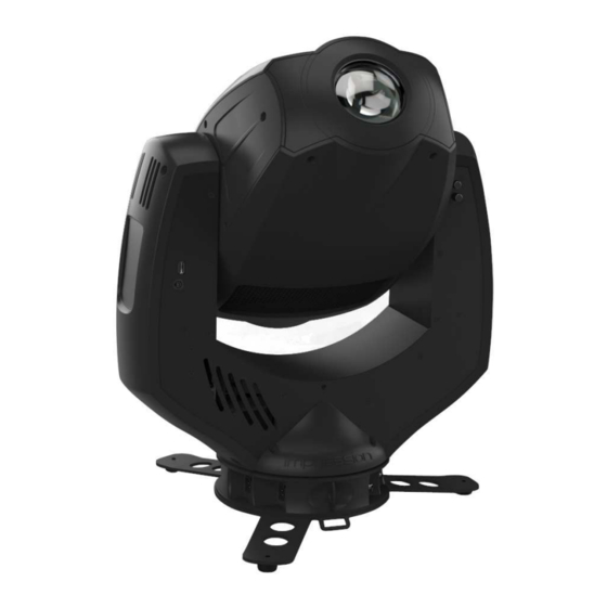
1 Description of Device 1. Moving Head 2. Arm with various cooling vents 3. Tilt-lock to secure and lock the tilt movement 4. Backlight LCD graphical menu (data entry) 5. Base with various connectors and Camlock mounting system 6. DMX- Output (5 Pin) Base Side 1 7. -
Page 5: Safety Instructions
9. Repair, maintenance and installation work should only be performed by qualified or GLP certified staff. You need to pay attention to the common German Light Products GmbH (Instruction version 1.93) / from software version 1.52... -
Page 6: Preparation And Installation
rules of technology that are not explicitly mentioned in this manual. 10. Use only original spare parts. Any structural modification on the system will terminate all warranty claims. 11. Please keep this instruction manual for future reference. 2 Preparation and Installation 2.1 Mounting e is fully operational whether it hangs or is mounted to a wall. -
Page 7: Mounting On The Floor (Upright)
2.1.1 Mounting on the floor (upright) To operate the e in an upright position, please use the dedicated floor-stand which is shipped with all original fixtures. The floor stand is mounted to the base of the fixture using the two Camlock quarter turn fasteners. -
Page 8: Mounting In Sideways Position
To operate the e in a sideways position, please use an additional mounting bar, available from GLP or one of their agents. This mounting bar is fixed via the four camlock quick-release connectors. Two half-couplers or clamps are then used to hang fixture. This technique is necessary to cope with the additional torque in this mounting position. -
Page 9: Connections
2.3 Connections 2.3.1 Power Supply Autosensing ~100-240 Volt AC, 50-60 Hz, earth contact type plug via Powercon Connected load 450 VA (W) <=> T8A (micro-fuse 6.3x32mm) Disconnect from the mains supply before changing the fuse and use only the above described micro-fuse type. 2.3.2 DMX USITT DMX-512 Standard input/output via 3 pin and 5 pin connectors. - Page 10 Allows selection of the desired DMX Mode Mode Fixture works in "Compressed" mode Compressed also section 4 Fixture works in "Normal" mode see also Normal section 4 Fixture works in "High Resolution" mode High- see also section 4 Resolution Defines whether the last DMX signal is stored, or the lamp is switched OFF in case of signal interruption Hold Values...
- Page 11 Resetting all functions to original values Set Default Status Version Shows the current software version Reset Hardware Hardware reset adjust Reset all boards Head Reset only headboard Reset only Gobo & Iris Reset only Focus, Zoom, Prism Reset only Pan Tilt Reset only Tilt Temperatures...
- Page 12 Effectwheel Instantaneous value for effect wheel rot. rot. Instantaneous value for prism Prisma Instantaneous value for iris Iris Adjustments for all functions. Use code to enter calibration. (only for authorized Service Adjust persons) Adjust for pan Tilt Adjust for tilt Gobo1 Adjust for Gobo 1 Gobo 1 rot.
-
Page 13: Dmx Channels
DMX Channels Normal-Mode 24 DMX Channels Channel Function Time and Value 1) PAN- coarse 0 .. 540° 0..255 00..FF 0..100 2) PAN-fine High- Pos ... High- Pos + 0..255 00..FF 0..100 2,6° (16 Bit) 3) Tilt- coarse 0 .. 280° 0..255 00..FF 0..100... - Page 14 270° 06..07 0° 08..09 90° 10..11 180° 12..13 270° 14..15 0° 16..17 90° 18..19 180° 20..21 270° 22..23 0° 24..25 90° 26..27 180° 28..29 270° 30..31 TILT size / phase see also 32..63 20..3F 13..25 PAN / TILT size / phase see also 64..95 40..5F 26..37...
- Page 15 Gobo rotation, fast-slow, 192..253 C0..FD 76..99 Gobo rotation STOP 254..255 FD..FF 99..100 19)Gobo2 Gobo 1 (open) 0…15 0..F 0..5,9 (indexed) Gobo 2 16..31 10..1F 6..11,9 Gobo 3 32..47 20.. 2F 12..17,9 Gobo 4 48..63 30.. 3F 19.. 24,5 Gobo 5 64..79 40..4F 25..30,5...
- Page 16 Compress-Mode 20 DMX Channels Channel Function Time and Value 1) PAN- coarse 0 .. 540° 0..255 00..FF 0..100 2) PAN-fine High- Pos ... High- Pos +(16 0..255 00..FF 0..100 Bit) 3) Tilt- coarse 0 .. 280° 0..255 00..FF 0..100 4) Tilt-fine High- Pos …...
- Page 17 Gobo rotation STOP Gobo rotation, slow-fast, 132..191 84..BF 53..75 Gobo rotation, fast-slow, 192..252 C0..FD 76..98 Gobo Open 253..255 FE..FF 99..100 14) Gobo 1 Gobo position 0 ... 540° 0..127 00..7F 0..49 Posi./Rot Gobo rotation STOP 128..129 80..81 Gobo rotation, slow-fast, 130..191 82..BF 51..75...
- Page 18 High Resolution (Extended)-Mode 31 DMX Channels Kanal Funktion Zeiten und Werte 1) PAN- coarse 0 .. 540° 0..255 00..FF 0..100 2) PAN-fine High- Pos ... High- Pos + (16 0..255 00..FF 0..100 Bit) 3) Tilt- coarse 0 .. 280° 0..255 00..FF 0..100 4) Tilt-fine...
- Page 19 18) Zoom fine Zoom low (0% - 100%) 0..255 0..FF 0..100 19) Focus coarse Stepless adjustable Focus infinity – near 0 .. 255 0..FF 0..100 20) Focus fine Focus low (0% - 100%) 0..255 0..FF 0..100 21)Gobo1 Gobo 1 (open) 0…15 0..F 0..5,9...
- Page 20 Prism rotation, slow-fast, CW 130..191 82..BF 51..75 Prism rotation, fast-slow, 192..253 C0..FD 76..99 Prism rotation stop 254..255 FD..FF 99.100 30) Iris coarse Iris open – closed 0..127 00..7F 00..50 31) Iris fine Iris low 0..255 00..FF 00..100 Locking and unlocking the Control Panel The Display will auto look automatically if the Touch Panel will not use for 10s.
-
Page 21: Changing Gobos And The Effect Wheel
4 Changing Gobos and the Effect wheel 4.1 Changing Gobos and the Effect wheel s equipped both with Aluminum- and Glass gobos (outside diameter 27 mm, image size 20 mm). When using customized Gobos like company logos and writing the recommended image size is 18 mm. You can use either Aluminum (thickness = 0.5 mm) or glass gobos (thickness = 1.1 - 3.0 mm). -
Page 22: Changing Rotating Gobos
structured surface towards the LED light source and the flat side towards the front lens. 4.1.2 Changing rotating gobos 1) Open the fixture, using the quarter turn screws on the top cover. 2) Press the gobo holder at the outer part of the wheel carefully out of the hub. - Page 23 Gobowheel 1 (Rotation Gobos Ø 27 mm ) Position 4 Circles Vertical Bars Two Light Tunnels Triangles Random Dash Mini Dots Medium Starry Night Dense German Light Products GmbH (Instruction version 1.93) / from software version 1.52...
- Page 24 Gobowheel 2 (Rotation Gobos Ø 27 mm) Position Cone Leaves Foliage Teeth Shreds Angry Hurricane Shredded Earth Diamond Pattern German Light Products GmbH (Instruction version 1.93) / from software version 1.52...
-
Page 25: Changing The Effect Wheel
4.1.3 Changing the effect wheel 1) Open the fixture. 2) Release the mechanical stop of the effect and move it up. 3) The Effect wheel can now be tilt out by hand. 4) The wheel itself is clipped on the wheel axis. 5) To remove it please use a slotted screwdriver and lift it out carefully from the wheel axis of the effect wheel. - Page 26 Effect wheel insertion and spares: STANDARD SPARE SPARE SPARE SPARE German Light Products GmbH (Instruction version 1.93) / from software version 1.52...
-
Page 27: Colored Error Code
5 Colored Error Code These state match to the following errors of the Impression Spot one: Color Meaning Comment critical state PCB could not find abnormal PCB send error back (hall sensor not found, encoder error, Yellow state …) Green normal state... -
Page 28: Maintenance Intervals (Rule-Of-Thumb)
6.2 Maintenance Intervals (rule-of-thumb) The maintenance schedule of any given fixture depends on the installation environment. Hence no specific guidelines can be given. The cleaning intervals given below are suggestions, based on practical experience. We suggest that you start with these and develop your own maintenance schedule as you see the fixtures performance in your specific environment. -
Page 29: Technical Specifications
7 Technical Specifications Power supply Power consumption 700 VA (Watt) Power input Auto sensing 100-240 V AC, 50-60 Hz Fuse protection Micro-fuse 6.3x32 mm, T8A Operational Parameters Max. ambient temp. 45° C / 113° F (integrated overheating switch) Mounting position Any (See Mounting chapter) Lighting System - Additive Color mixing LED type... -
Page 30: Index
8 Index Menu Field ............9 Menüfeld ............9 Anleitung Version ..........1 Micro-fuse ............9 Mode-key ............9 Mounting ............6 BGV C1............6 Mounting in hanging Position ......7 Mounting on the Floor ........7 Changing Effect wheel ........25 Circumference .......... - Page 31 German Light Products GmbH (Instruction version 1.93) / from software version 1.52...
Need help?
Do you have a question about the impression spot one and is the answer not in the manual?
Questions and answers