Table of Contents
Advertisement
Quick Links
Advertisement
Table of Contents

Related Manuals for GRAPHTEC CS510 SERIES


Summary of Contents for GRAPHTEC CS510 SERIES
- Page 1 IMAGE SCANNER CS510/IS210 SERIES SERVICE MANUAL CS510/IS210-UM251-02-9370...
- Page 3 HISTORY OF REVISIONS No. Date issued Description of revision Page Edition 08.04.28 First Printing. 08.05.28 The IS0917 and the IS0907 were assigned to consumable supplies parts. 13-13 08.05.28 The IS0918 was added to consumable supplies parts. 12-1 CS510/IS210-UM-251-9370...
-
Page 4: Table Of Contents
CONTENTS 1. OVERVIEW ................... 1-1 1.1 Features ....................1-1 1.2 Standard Specifications ................1-2 1.3 External View ..................1-6 2. PART NAMES AND FUNCTIONS ............ 2-1 2.1 Part Names and Functions ..............2-1 3. PREPARING TO OPERATE THE SCANNER ........3-1 3.1 System Requirements ................ - Page 5 8. DISASSEMBLING AND ADJUSTING THE MECHANICAL PARTS ........8-1 8.1 Right Side Cover ..................8-1 8.2 Left Side Cover ..................8-1 8.3 Top Cover Assembly ................8-2 8.4 Front Guide Assembly ................8-2 8.5 Rear Cover ....................8-3 8.6 Motor .....................8-4 8.7 Drive Roller Pulley ..................
- Page 6 10. ADJUSTMENTS USING THE SOFTWARE ........10-1 10.1 Starting the Software ................10-1 10.2 Preparations before Making Adjustments ..........10-4 10.3 Preparing Adjustment Charts ..............10-5 10.4 Making Adjustments ................10-7 10.4.1 Calibration (white correction) ............10-8 10.4.2 Feed distance adjustment ............10-10 10.4.3 Sensor Stitch Adjustment ............
-
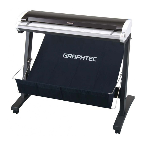
Page 7: Overview
Compatible with document sizes from ISO A4 up to ANSI E • Capable of color and grayscale scanning The CS510 Series scanners are capable of scanning in color (24-bit color, 8-bit color) or grayscale (256 shades). The IS210 Series scanners are capable of scanning in grayscale (256 shades). -
Page 8: Standard Specifications
1. OVERVIEW 1.2 Standard Specifications Item CS510-11eN//CS510-11eN-PRO Document size ANSI E to ISO A4 Maximum width: 1092 mm; minimum width: 210 mm Effective scanning area Width : 1066 mm (centered) Length : 16 m Guaranteed scanning 841 mm x 1189 mm precision range Document thickness 1.5 mm or less (including the carrier sheet) - Page 9 1. OVERVIEW *3 Notes on scanning precision Scanning precision may vary slightly depending on the grade and thickness of the medium being scanned, and on the operating conditions. The precision figures above were measured under the operating conditions described below. •...
- Page 10 1. OVERVIEW Item IS210-11eN/IS210-11eN-PRO Document size ANSI E to ISO A4 Maximum width: 1092 mm; minimum width: 210 mm Effective scanning area Width : 1066 mm (centered) Length : 16 m Guaranteed scanning 841 mm x 1189 mm precision range Document thickness 1.5 mm or less (including the carrier sheet) Optical resolution...
- Page 11 1. OVERVIEW *4 The USB 2.0 interface cannot be used at the same time as the Ethernet interface. CS510/IS210-UM-251-9370...
-
Page 12: External View
1. OVERVIEW 1.3 External View External Dimensions 1205 Unit : mm Dimensional precision error : ±5 mm CS510/IS210-UM-251-9370... -
Page 13: Part Names And Functions
2. PART NAMES AND FUNCTIONS PART NAMES AND FUNCTIONS 2.1 Part Names and Functions Front View Paper sensor Control panel Top cover Cover sensor Document guides Paper sensor Lock Basket Release Release Stand Caster Top cover Open the top cover to clean the document hold-down unit and transparent contact plates. Paper sensors These sense whether a document is present in the scanner. -
Page 14: Power Switch
2. PART NAMES AND FUNCTIONS Rear View Power switch Interface selection switch connector AC line inlet Ethernet connector Power switch Controls the on/off status of the power supply to the scanner. AC line inlet Connect the power cord’s female plug here. USB connector Used to connect the USB interface cable. -
Page 15: Control Panel
2. PART NAMES AND FUNCTIONS Control panel POWER LED POWER Unlit : Is unlit while the scanner is turned off. PAPER ERROR Lit (green) : Lights when the scanner is turned and remains lit while it is operating normally. SCAN Flashing (orange) : Flashes when the scanner is in power-saving mode. -
Page 17: Preparing To Operate The Scanner
*1 If your scanner does not operate with the USB interface that comes with your computer, or if your computer does not have a USB 2.0 interface, please contact your sales representative or nearest Graphtec vendor for information on supported add-on cards. Recommended environment... -
Page 18: Connecting The Scanner To A Power Supply
3. PREPARING TO OPERATE THE SCANNER 3.2 Connecting the Scanner to a Power Supply Insert the female plug of the power cord provided into the scanner’s AC line inlet and insert its male plug into an electrical socket supplying AC voltage. Check that the scanner’s Power switch remains in the Off position until the connection of the power cord has been completed. - Page 19 3. PREPARING TO OPERATE THE SCANNER Turning the Scanner On or Off Whenever the scanner's Power switch is turned on, the POWER, PAPER, and ERROR lamps on the control panel light up. When the scanner has been initialized, the POWER lamp lights up. When resetting the scanner by turning it off then back on again, wait at least five seconds before turning it back on.
-
Page 20: Connecting The Scanner To A Computer
3. PREPARING TO OPERATE THE SCANNER 3.3 Connecting the Scanner to a Computer The scanner can be connected to a computer using the USB interface or the Ethernet interface. The operation of the scanner cannot be guaranteed in the following cases: •... - Page 21 3. PREPARING TO OPERATE THE SCANNER Connecting the scanner via an Ethernet interface (1) Move the interface selection switch to the Ethernet (LAN) position. (2) Ensure that you have an Ethernet cable that works with your computer. Plug the Ethernet cable into the Ethernet connector located on the right-hand side of the scanner unit. Interface selection switch Ethernet...
-
Page 23: Installing The Software
4. INSTALLING THE SOFTWARE INSTALLING THE SOFTWARE The procedure outlined below is based on the requirement that you are logged on to Windows with administrator rights. Consult your Windows 2000, Windows XP or Windows Vista manual or Windows Help for more information. 4.1 Installing the Driver Software 4.1.1 Installing the Driver Software for Windows 2000 The following procedure assumes that you are using the CS510-11eN as part of your system, and that... - Page 24 4. INSTALLING THE SOFTWARE (5) Select the option “Search for a suitable driver for my device (recommended)” and click Next. (6) Select the check box entitled “Specify a location” and click Next. Click Browse and select the DRIVER folder in the CD-ROM drive or enter a CD-ROM drive name and \DRIVER using the keyboard.
- Page 25 4. INSTALLING THE SOFTWARE (8) The screen shown below is displayed when you click Next. Click Yes to continue the installation. (9) The screen shown below is displayed when the wizard has finished installing the driver. Click the Finish button. (10) The Windows 2000 Desktop appears and the Scanner is acknowledged by the computer.
-
Page 26: Installing The Driver Software For Windows Xp
4. INSTALLING THE SOFTWARE 4.1.2 Installing the Driver Software for Windows XP The following procedure assumes that you are using the CS510-11eN as part of your system, and that you are using the USB interface. The scanner name displayed in the windows is the name of the scanner connected to the computer (CS510-11eN is used in this section). - Page 27 4. INSTALLING THE SOFTWARE (5) The screen shown below is displayed. Click Continue Anyway to continue the installation. (6) The screen shown below is displayed when the wizard has finished installing the driver. Click the Finish button to close the “Welcome to the Found New Hardware” wizard. (7) The Windows XP desktop appears, and the scanner is recognized by the computer.
-
Page 28: Installing The Driver Software For Windows Vista
4. INSTALLING THE SOFTWARE 4.1.3 Installing the Driver Software for Windows Vista The following procedure assumes that you are using the CS510-11eN as part of your system, and that you are using the USB interface. The scanner name displayed in the windows is the name of the scanner connected to the computer (CS510-11eN is used in this section). - Page 29 4. INSTALLING THE SOFTWARE (5) Click “Don’t search online”. The following window appears. (6) Click “I don’t have the disc. Show me other options.” The following window appears. (7) Click “Browse my computer for driver software (advanced)”. The following window appears. Click [Browse] and select the DRIVER folder in the CD-ROM drive or enter the CDROM drive name and \DRIVER using the keyboard.
- Page 30 4. INSTALLING THE SOFTWARE (8) When you click [Next] the wizard will start searching for the driver. (9) The following window appears. Click [Install] to continue the installation. (10) The screen shown below is displayed when the wizard has finished installing the driver. Click [Close] to close the “Found New Hardware”...
-
Page 31: Checking The Interface Connection For Windows 2000
The scanner name displayed in the windows is the name of the scanner connected to the computer (CS510- 11eN is used in this section). (1) Launch the Control Panel using the Start menu. (2) The screen shown below is displayed when you click on the “Scanners and Cameras” icon. Ensure that “Graphtec CS510-11eN” is indicated here. CS510/IS210-UM-251-9370... -
Page 32: Checking The Interface Connection For Windows Xp
(2) The screen shown below is displayed when you click on the “Printers and Other Hardware” icon. (3) The screen shown below is displayed when you click on the “Scanners and Cameras” icon. Ensure that “Graphtec CS510-11eN” is indicated here. CS510/IS210-UM-251-9370... -
Page 33: Checking The Interface Connection For Windows Vista
(2) The screen shown below is displayed when you click on the "Hardware and Sound”. (3) The screen shown below is displayed when you click on the “Scanners and Cameras” icon. Ensure that “Graphtec CS510-11eN” is indicated here. CS510/IS210-UM-251-9370 4-11... -
Page 34: Installing The Scanning Master 21+ Application
4. INSTALLING THE SOFTWARE 4.3 Installing the Scanning Master 21+ Application The Scanning Master 21+ “OPS112” is a software application for using a Graphtec scanner to scan image data. Operating Environment Windows 2000 Professional/XP Professional/XP Home Edition/Vista Installation Procedure (The following steps are explained using the Windows 2000 windows.) (1) Boot Windows 2000. -
Page 35: Daily Maintenance
5. DAILY MAINTENANCE DAILY MAINTENANCE 5.1 Opening and Closing the Top Cover (1) Turn off the scanner’s power. (2) Push the left and right open levers on the top cover to unlock them, and hold the middle part of the top cover while you open the top cover by about 90 degrees. -
Page 36: Cleaning The Document Hold-Down Unit
5. DAILY MAINTENANCE 5.2 Cleaning the Document Hold-Down Unit Turn off the scanner. (2) Open the top cover as described in Section 5.1 “Opening and Closing the Top Cover”. (3) Wipe clean the underside of the document hold-down unit (see below) using a soft cloth that has been soaked in water or diluted neutral detergent and thoroughly wrung out. -
Page 37: Cleaning The Image Sensors
5. DAILY MAINTENANCE 5.3 Cleaning the Image Sensors The scanner’s image quality drops when the transparent contact plates over the image sensors become dirty, so clean the image sensors whenever necessary. Procedure (1) Turn off the scanner. (2) Open the top cover as described in Section 5.1 “Opening and Closing the Top Cover”. (3) As shown below, wipe off any soiled areas on the transparent contact plates using a soft cloth that has been moistened with water or a neutral detergent (diluted with water) and firmly wrung out. -
Page 38: Cleaning The Paper Sensors
5. DAILY MAINTENANCE 5.4 Cleaning the Paper Sensors Accumulated dust on the paper sensors may prevent the document from being detected. The sensors must be cleaned when necessary. (1) Turn off the scanner. (2) Open the top cover as described in Section 5.1 “Opening and Closing the Top Cover”. (3) Wipe the two paper sensors using a cotton swab. -
Page 39: Removing A Jammed Document
5. DAILY MAINTENANCE 5.5 Removing a Jammed Document If a document becomes jammed in the scanner during scanning or another operation, immediately turn off the scanner and then remove the jammed document. Procedure (1) Turn off the scanner. (2) Open the top cover as described in Section 5.1 “Opening and Closing the Top Cover”. (3) If the document is jammed at the front, remove the document from the inside by pulling it forward. -
Page 40: Calibration
• The calibration sheet is a paper product. Do not attempt to clean it with any type of liquid cleaner. • The calibration sheet is a consumable item. Replacement sheets can be purchased from your sales representative or nearest Graphtec vendor. Preparation and checks Recommended usage environment •... -
Page 41: Scanner Calibration
5. DAILY MAINTENANCE Scanner Calibration Before beginning calibration, clean the transparent contact plates and scanner table surface. Any dust or dirt on this surface may affect calibration results and resulting image quality. Check that the calibration sheet is free of any dust or dirt. The calibration procedure will take some time. - Page 42 5. DAILY MAINTENANCE (10) To check the calibration results, click the Confirm button in the Calibration menu (shown in step (5) above). (11) The following message is displayed. Insert the calibration sheet into the scanner as instructed. (12) Click the OK button to start scanning. The scanned data is displayed when scanning is complete.
-
Page 43: Color Correction
5. DAILY MAINTENANCE Color Correction Perform color correction if there is any discrepancy in color in parts of the scanned image even after you have calibrated the scanner. (1) Select Color Correction on the Scanner menu. (2) Click the Scan button. (3) The following message is displayed. - Page 44 5. DAILY MAINTENANCE (7) After you have clicked tile number 6, click the Set button. Click the OK button. (8) To check the color correction results, click the Confirm button. (9) The following message is displayed. Insert the color correction sheet in the scanner as instructed. Position the color correction sheet so that the red bar in the center of the sheet is centered in the scanner (but with the printed side down).
-
Page 45: Recommended Parts List
6. RECOMMENDED PARTS LIST RECOMMENDED PARTS LIST Part No. Part Name Description Q'ty Remarks 444105010 Data Controller Board CS510-11eN 444105000 Data Controller Board CS510-11eN-PRO 444105060 Data Controller Board IS210-11eN 444105050 Data Controller Board IS210-11eN-PRO 794210700 Data Controller Board IS210-11eN-AP 794050003 CIS Controller Board 794050004 CIS Power Board 774019980 CIS Sensor Assembly, Rank A 774019981 CIS Sensor Assembly, Rank B... -
Page 47: List Of Jigs And Tools
7. LIST OF JIGS AND TOOLS LIST OF JIGS AND TOOLS 7.1 Jigs Jigs Adjustments Remarks sc_csis4vxxx.x •Downloading system program Firmware (CS510/IS210) OPS112 (Ver. 6.60 or later) •Downloading system program Software supplied with the scanner •Shading (white correction) (Scanning Master 21+) •Adjusting feed distance •Aligning sensor images •Adjusting offset... -
Page 49: Disassembling And Adjusting The Mechanical Parts
8. DISASSEMBLING AND ADJUSTING THE MECHANICAL PARTS DISASSEMBLING AND ADJUSTING THE MECHANICAL PARTS 8.1 Right Side Cover Detaching the right side cover (1) Remove the three M4L6 binding head screws on the right side of the scanner unit. (2) Detach the right side cover as shown below. M4L6 Binding Head Screw Right Side Cover... -
Page 50: Top Cover Assembly
8. DISASSEMBLING AND ADJUSTING THE MECHANICAL PARTS 8.3 Top Cover Assembly Detaching the top cover (1) Detach the right and left side covers (see Sections 8.1 and 8.2). (2) Remove the four M3L10 cap screws and the two M3L14 cap screws on both sides of the plate. (3) Detach the top cover assembly from the scanner unit as shown below. -
Page 51: Rear Cover
8. DISASSEMBLING AND ADJUSTING THE MECHANICAL PARTS 8.5 Rear Cover Detaching the rear cover (1) Remove the four M3L6 binding head screws at the back of the scanner unit. M3L6 Binding Head Screw (2) Detach the rear cover. Reattaching the rear cover (1) Reattach the rear cover in the reverse order in which it was detached. -
Page 52: Motor
8. DISASSEMBLING AND ADJUSTING THE MECHANICAL PARTS 8.6 Motor Detaching the motor (1) Detach the left side cover (see Section 8.2). (2) Detach the front guide assembly (see Section 8.4). (3) Disconnect the J4 connector from the data power board. (4) Remove the two M4L6 binding head screws holding the motor. -
Page 53: Drive Roller Pulley
8. DISASSEMBLING AND ADJUSTING THE MECHANICAL PARTS 8.7 Drive Roller Pulley Detaching the drive roller pulleys (1) Detach the left side cover (see Section 8.2). (2) Loosen the two M4L6 binding head screws holding the motor. Belt M4L6 binding head screws (3) Detach the drive belt from the pulleys. -
Page 54: Drive Rollers
8. DISASSEMBLING AND ADJUSTING THE MECHANICAL PARTS 8.8 Drive Rollers Detaching the front drive roller (1) Detach the right and left side covers (see Sections 8.1 and 8.2). (2) Detach the front guide assembly (see Section 8.4). (3) Detach the drive roller belt and the pulley from the drive roller (see Section 8.7). (4) Detach the E-ring holding the drive roller. - Page 55 8. DISASSEMBLING AND ADJUSTING THE MECHANICAL PARTS Reattaching the drive rollers (1) Reattach the drive rollers by reversing the sequence of steps in which they were detached. (2) The front drive roller and the rear drive roller are different. When installing a drive roller, check the mark on it to make sure that you have the correct one. Install the drive roller with Install the drive roller with this mark at the front.
-
Page 56: Drive Belt
8. DISASSEMBLING AND ADJUSTING THE MECHANICAL PARTS Drive Belt Detaching the drive belt (1) Detach the left side cover (see Section 8.2). (2) Loosen the two M4L6 binding head screws holding the motor. (3) Detach the drive belt from the pulleys. Belt M4L6 binding head screws... -
Page 57: Top Cover Sensor
8. DISASSEMBLING AND ADJUSTING THE MECHANICAL PARTS 8.10 Top Cover Sensor Detaching the left side top cover sensor (1) Detach the right and left side covers (see Sections 8.1 and 8.2). (2) Detach the front guide assembly (see Section 8.4). (3) Remove the two M3L6 binding head screws holding the left side top cover sensor bracket. -
Page 58: Front And Rear Paper Detection Sensors
8. DISASSEMBLING AND ADJUSTING THE MECHANICAL PARTS 8.11 Front and Rear Paper Detection Sensors Detaching the front paper detection sensor (1) Detach the right and left side covers (see Sections 8.1 and 8.2). (2) Detach the front guide assembly (see Section 8.4). (3) Remove the M3L10 binding head screws holding the front paper detection sensor. -
Page 59: Control Panel Sheet Switch
8. DISASSEMBLING AND ADJUSTING THE MECHANICAL PARTS 8.12 Control Panel Sheet Switch Detaching the control panel sheet switch (1) Detach the right cover (see Section 8.1). (2) Disconnect the flexible cable from the control panel relay board and then pull off the control panel sheet switch from the right side cover. -
Page 60: Contact Glass Assembly
8. DISASSEMBLING AND ADJUSTING THE MECHANICAL PARTS 8.13 Contact Glass Assembly Detaching the contact glass assembly (1) Open the center cover. (2) Remove the six M2L5 binding head screws holding the front contact glass stopper plate. M2L5 binding head screw M2L5 binding head screw M2L5 binding head screw M2L5 binding head screw... -
Page 61: Cis (Charge Coupled Device Imaging Sensor) Assembly
8. DISASSEMBLING AND ADJUSTING THE MECHANICAL PARTS 8.14 CIS (Charge Coupled Device Imaging Sensor) Assembly Detaching the CIS assembly (1) Detach the contact glass assembly (see Section 8.13). (2) Slide each CIS assembly to the left side, lift it up from the right side, and then detach each CIS assembly. - Page 62 8. DISASSEMBLING AND ADJUSTING THE MECHANICAL PARTS Reattaching the CIS assembly (1) Reattach each CIS assembly in the reverse order in which it was detached. (2) Use a CIS sensor of the same rank when replacing a CIS sensor. CIS sensor rank is indicated on the CIS sensor unit. If there is no rank shown on the sensor, you had better replace all five sensors.
-
Page 63: Cis (Charge Coupled Device Imaging Sensor) Board
8. DISASSEMBLING AND ADJUSTING THE MECHANICAL PARTS 8.15 CIS (Charge Coupled Device Imaging Sensor) Board Detaching the CIS boards (1) Detach the contact glass assembly (see Section 8.13). (2) Detach each CIS assembly (see Section 8.14). (3) Remove the two M2L5 binding head screws supporting each CIS board. CIS board CIS board M2L5 binding head screw... -
Page 64: Pinch Roller Covers
8. DISASSEMBLING AND ADJUSTING THE MECHANICAL PARTS 8.16 Pinch Roller Covers Detaching the rear pinch roller cover (1) Remove the two M3L8 binding head screws and the bushes holding the rear pinch roller cover. M3L8 binding head screw (2) Remove the three M3L6 binding head screws holding the rear pinch roller cover from the rear of the scanner. - Page 65 8. DISASSEMBLING AND ADJUSTING THE MECHANICAL PARTS Detaching the front pinch roller cover (1) Remove the four M3L8 binding head screws and the bushes holding the front pinch roller cover. M3L8 binding head screw (2) Loosen the two M3L6 binding head screws holding the front pinch roller cover holding bracket. (3) Slide the front pinch roller cover holding bracket to the left and then detach the front pinch roller cover.
-
Page 66: Document Hold-Down Rollers
8. DISASSEMBLING AND ADJUSTING THE MECHANICAL PARTS 8.17 Document Hold-down Rollers Detaching the document hold-down rollers (1) Detach the pinch roller covers (see Section 8.16). (2) Remove the three M3L6 binding head screws holding each document hold-down roller spring plate. M3L6 binding head screw M3L6 binding head screw M3L6 binding head screw... -
Page 67: Pinch Roller Units
8. DISASSEMBLING AND ADJUSTING THE MECHANICAL PARTS 8.18 Pinch Roller Units Detaching the front pinch roller units (1) Detach the pinch roller covers (see Section 8.16). (2) Remove the two M3L6 binding head screws holding the four pinch rollers unit assembly. Detach the four pinch rollers unit assembly from the top cover assembly. -
Page 68: Ethernet Board
8. DISASSEMBLING AND ADJUSTING THE MECHANICAL PARTS 8.19 Ethernet Board Detaching the ethernet board (1) Detach the right and left side covers (see Sections 8.1 and 8.2). (2) Detach the front guide assembly (see Section 8.4). (3) Disconnect all the connectors on the ethernet board. Ethernet Board M3L6 binding head screw (4) Remove the four M3L6 binding head screws holding the ethernet board and then detach the ethernet... -
Page 69: Data Controller Board
8. DISASSEMBLING AND ADJUSTING THE MECHANICAL PARTS 8.20 Data Controller Board When replacing the data controller board, perform the software adjustment to obtain the former setting values from the data controller board. Detaching the data controller board (1) Detach the right and left side covers (see Sections 8.1 and 8.2). (2) Detach the front guide assembly (see Section 8.4). - Page 70 8. DISASSEMBLING AND ADJUSTING THE MECHANICAL PARTS (6) Remove the two M2L4 fl at head screws holding the I/F selector switch braket and then detach the I/F selector switch braket from the main unit. M2L4 Flat head screw (7) Remove the M2L4 fl at head screw and the two M3L6 binding head screws holding the I/F board and then detach the I/F board from the data controller board.
- Page 71 8. DISASSEMBLING AND ADJUSTING THE MECHANICAL PARTS Reattaching the data controller board (1) Reattach the data controller board in the reverse order in which it was detached. (2) Prepare corresponded the data controller board before replacing the data controller board. (3) Set the DIP switch setting for each model (See "Replacing the Data Controller Board"...
-
Page 72: Power Board
8. DISASSEMBLING AND ADJUSTING THE MECHANICAL PARTS 8.21 Power Board Detaching the power board (1) Detach the right and left side covers (see Sections 8.1 and 8.2). (2) Detach the front guide assembly (see Section 8.4). (3) Remove the six M3L6 binding head screws holding the power board. M3L6 binding head screw (4) Disconnect all the connectors on the power board. -
Page 73: Switching Power Supply Board
8. DISASSEMBLING AND ADJUSTING THE MECHANICAL PARTS 8.22 Switching Power Supply Board Detaching the switching power supply board (1) Detach the right and left side covers (see Sections 8.1 and 8.2). (2) Detach the front guide assembly (see Section 8.4). (3) Remove the four M3L6 binding head screws holding the switching power supply board. -
Page 75: Boards And Electrical Components
9. BOARDS AND ELECTRICAL COMPONENTS BOARDS AND ELECTRICAL COMPONENTS 9.1 Wiring Diagrams CS510/IS210-UM-251-9370... -
Page 76: Replacing The Data Controller Board
9. BOARDS AND ELECTRICAL COMPONENTS 9.2 Replacing the Data Controller Board 1. Precautions for replacing the data controller board (1) Prepare corresponded the data controller board before replacing the data controller board. (2) Before replacing the data controller board, note the feed correction value, X overlap and Y offset values currently selected for the scanner, if these values can be checked. -
Page 77: Replacing The Ethernet Board
9. BOARDS AND ELECTRICAL COMPONENTS 9.3 Replacing the Ethernet Board (1) After replacing the Ethernet board, you need to input the MAC address to the ethernaet board. (2) Use Scanning Master 21+ to input the MAC address. Input the MAC address to the ethernet board (1) Use the USB cable to connect the CS510/IS210 and PC. -
Page 78: Downloading Firmware
9. BOARDS AND ELECTRICAL COMPONENTS 9.4 Downloading Firmware This section describes how to download firmware (system programs) via the USB interface to the flash memory provided on the data controller board, to which the boot program has been downloaded. 1. Items required to download firmware •... -
Page 79: Adjustments Using The Software
10. ADJUSTMENTS USING THE SOFTWARE 10. ADJUSTMENTS USING THE SOFTWARE 10.1 Starting the Software • Ensure that OPS112 (Scanning Master 21+ Ver 6.60 or later) is installed. Connect the scanner to the PC using a USB cable and switch on the scanner. (2) Start Windows (OS). - Page 80 10. ADJUSTMENTS USING THE SOFTWARE (7) The following message is displayed when the scanner is detected. Click "OK" button. (8) Select "About" from the "Help" menu. (9) Click the scanner icon while pressing and holding down the "Ctrl" key. Next, click the "OK" button while pressing and holding down the "Shift" key. Icon (10) Select "Adjust Scanner"...
- Page 81 10. ADJUSTMENTS USING THE SOFTWARE (12) When you click the "OK" button in the following window, the Scanner Adjustment window will appear with an Adjust menu. CS510/IS210-UM-251-9370 10-3...
-
Page 82: Preparations Before Making Adjustments
10. ADJUSTMENTS USING THE SOFTWARE 10.2 Preparations before Making Adjustments Note the current feed distance adjustment and position adjustment values while making adjustments. This enables the values to be entered directly from the keyboard to restore the scanner to its previous status if adjustment fails. -
Page 83: Preparing Adjustment Charts
10. ADJUSTMENTS USING THE SOFTWARE 10.3 Preparing Adjustment Charts There are the three kind of adjustment charts. • Calibration Sheet: This sheet is used for the sensor sensitivity adjustment. 1070 mm 220 mm Calibration sheet • C600/500/IS200 adjustment test chart: This chart is used for the manual sensor stitch adjustment, the feed distance adjustment and the scanning start position adjustment. - Page 84 B056 B056 C056 C056 D056 D056 B057 B057 C057 C057 D057 D057 B058 B058 B058 B058 B058 C058 C058 D058 D058 D058 D058 D058 10. ADJUSTMENTS USING THE SOFTWARE B059 B059 B059 B059 B059 C059 C059 D059 D059 D059 D059 D059 B060 B060...
-
Page 85: Making Adjustments
10. ADJUSTMENTS USING THE SOFTWARE 10.4 Making Adjustments When you replaced the main board or the CIS sensors, follow the sequence of adjustments below. 1. Calibration (white correction) 2. Feed distance adjustment 3. Sensor stitch alignment 4. Scanning start position adjustment 5. -
Page 86: Calibration (White Correction)
10. ADJUSTMENTS USING THE SOFTWARE 10.4.1 Calibration (white correction) In the following cases, perform this adjustment. • When difference color appeared between each sensor. • When you replaced the main board. • When you replaced the CIS board. • When you replaced or removed the CIS sensors. •... - Page 87 10. ADJUSTMENTS USING THE SOFTWARE (7) Click the OK button to start scanning. The scanned data is displayed when scanning is complete. Colors may differ slightly for individual sensors to make it easier to identify problem areas in calibration. This does not indicate a defect. Check that there are no vertical streaks, such as white patches, in the scanned data.
-
Page 88: Feed Distance Adjustment
10. ADJUSTMENTS USING THE SOFTWARE 10.4.2 Feed distance adjustment In the following cases, perform this adjustment. • When the distance is different in the direction of the feed. • When you replaced the main board. • When you replaced or removed the CIS sensors. •... - Page 89 10. ADJUSTMENTS USING THE SOFTWARE (6) The following dialog box will appear. Click the "Scan" button. Select the following for "Document Info" and "Scan Settings": "Document Info" Paper Size : User Size, Width: 1066, Length 1100, Resolution: 600 dpi Document Type : Black and White "Scan Settings"...
- Page 90 10. ADJUSTMENTS USING THE SOFTWARE (7) Input the distance between C010 and C090 measured with a glass scale in the "Actual" box. (8) Click anywhere within the "Theoretical" box and use the crosshairs cursor to click the white corner indicated by arrow "C010" on the scanned image. (9) Scroll the scanned image to click the white corner indicated by arrow "C090"...
-
Page 91: Sensor Stitch Adjustment
10. ADJUSTMENTS USING THE SOFTWARE 10.4.3 Sensor Stitch Adjustment In the following cases, perform this adjustment. • When the sensor jointing is misaligned. • When you replaced the main board. • When you replaced or removed the CIS sensors. Adjusting the sensor stitch by manual sensor stitch adjustment (1) Prepare the CS600/500/IS200 Test Chart. - Page 92 10. ADJUSTMENTS USING THE SOFTWARE (4) Select "Adjust Position" from the "Adjust" menu. (5) The following dialog box will appear. Confirm that the CS600/500/IS200 Test Chart is inserted to the scanner correctly, and then click the "Scan" button. (6) The following dialog box will appear. Click the "Scan" button. CS510/IS210-UM-251-9370 10-14...
- Page 93 10. ADJUSTMENTS USING THE SOFTWARE (7) The image appears as shown below. Then confirm the jointing area of sensors from the A area to E area. At this time, confirm around 017 lines, because the top part of target is not stable to contact the CIS sensors.
- Page 94 10. ADJUSTMENTS USING THE SOFTWARE Image after adjustments Tips for Making Fine Adjustments • Two portions of the aligned image become misaligned during adjustments using the crosshairs cursor. • You wish to move a portion of the image by one pixel. •...
-
Page 95: Scanning Start Position Adjustment
10. ADJUSTMENTS USING THE SOFTWARE 10.4.4 Scanning Start Position Adjustment In the following cases, perform this adjustment. • When the start position is shifted. • When the stitch of sensors were adjusted by the auto-stitch adjustment. • When you replaced or removed the paper edge detecting sensor. •... - Page 96 10. ADJUSTMENTS USING THE SOFTWARE (5) The following dialog box will appear. And confirm the scanning condition. Then click the "Scan" button. Scan conditions: "Document Info" Paper Size: User Size, Width: 1066, Length 200, Resolution: 600 dpi Document Type: Black and White "Scan Settings"...
- Page 97 10. ADJUSTMENTS USING THE SOFTWARE (6) Check the scanning point of the top center area. Adjust this gap if there is gap between the target edge and the scanning start point. (7) Zoom in to the top center area using the zoom button. If the start point of the scanning is within the top center area as shown below, it does not require offset adjustment.
- Page 98 10. ADJUSTMENTS USING THE SOFTWARE (12) The following dialog box will appear. Then click the "Scan" button. (13) Zoom in to the top center circle using the zoom button. (14) Click anywhere within the Origin box. The crosshairs cursor appears in the Scanner Adjustment window. CS510/IS210-UM-251-9370 10-20...
- Page 99 10. ADJUSTMENTS USING THE SOFTWARE (15) When the crosshairs cursor appears in the Scanner Adjustment window, click on the center of the top center edge with the crosshairs cursor. Click here with the crosshairs cursor. (16) Click the "Check" button, then click the "Set" button. The following dialog box will appear. Click the "OK"...
-
Page 100: Color Correction (Using A Color Correction Sheet), Cs510 Only
10. ADJUSTMENTS USING THE SOFTWARE 10.3 Color correction (using a color correction sheet), CS510 only (1) Prepare the color correction sheet. (2) Select “Color Correction” from the “Adjust” menu. (3) Click the Scan button. (4) The following message is displayed. Insert the color correction sheet in the scanner. Position the color correction sheet so that the red bar in the center of the sheet is centered in the scanner (but with the printed side down). - Page 101 10. ADJUSTMENTS USING THE SOFTWARE (7) Click in the center of the color tile indicated by the numbers 1 to 6, in ascending order. For numbers 1 to 5, click the center of the upper left tile; for number 6, click in the center of the bottom right tile.
- Page 102 10. ADJUSTMENTS USING THE SOFTWARE (11) Click the OK button to start scanning. After scanning has been completed, an enlarged view of the color-corrected data is displayed. (12) Click the Fit icon to display the entire image, and check whether there is any discrepancy in color. If there is no discrepancy, color correction is complete.
-
Page 103: Troubleshooting
11. TROUBLESHOOTING 11. TROUBLESHOOTING Cause Checkpoint Remedy Lamps on the control Confirm that the power switch has been Switch on the power switch. panel remain unlit. switched on. Confirm that the power cable is properly Connect the cable properly. connected. Confirm that the cable is properly connected Connect the cable properly. - Page 104 11. TROUBLESHOOTING Cause Checkpoint Remedy The scanned drawing Clean the scanning glass and replace if Clean the scanning glass and replace if has undesired black necessary. necessary. lines. Clean the image sensors. Confirm that calibration (white correction) Perform calibration from the beginning (white has been properly performed.
- Page 105 11. TROUBLESHOOTING Cause Checkpoint Remedy There is a difference The sensor color density has not been Adjust color density. in color density properly corrected. between the right- and left-hand portions of the document scanned in grayscale. CS510/IS210-UM-251-9370 11-3...
-
Page 107: Optional Item
12. OPTION 12. OPTION 12.1 Optional Item Code Item Name OPS115-KIT-E Software to upgrade OPS112 Scanning Master 21+ to OPS115 Scanning Master Pro Color 12.2 Consumables Code Item Name IS0907 Carrier Sheet (A0) IS0908 Carrier Sheet (A1) IS0917 Calibration Sheet (CS510-11/IS210-11eN-PRO) IS0918 Calibration Sheet (IS210-11eN) EM-CP... -
Page 109: Parts List
13. PARTS LIST 13. PARTS LIST Regarding the rank of spare parts Rank A: This rank of part will be stocked always until product discontinued. Rank B: This rank of part will not be stocked always. This parts will need a lead time maximumly 3 month. Rank C: This rank of part will not be stocked always. -
Page 110: Main Frame
13. PARTS LIST 13.2 Main Frame Part No. Part name Description Q'ty Remarks 480063103 M3L10 Cap Screw 480063143 M3L14 Cap Screw 393230160 Spacer BSB-316 444105010 Data Controller Board CS510 CS510-11eN 444105000 Data Controller Board CS510PRO CS510-11eNPro 444105060 Data Controller Board IS210 IS210-11eN 444105050 Data Controller Board IS210PRO Is210-11eNPro... - Page 111 13. PARTS LIST Main Frame CS510/IS210-UM-251-9370 13-3...
-
Page 112: Front Guide
13. PARTS LIST 13.3 Front Guide Part No. Part name Description Q'ty Remarks 480003161 M3L16 Binding Head Screw 480033081 M3L8 Flat Head Screw 641050000 Front Guide 42-5121 774016500 Collar 5-7.5 641301200 Pulley Bracket 361204001 Edging Plate 641300290 Wire 350195011 Pulley VDC-277/57 641300202 Right Guide 641300212 Left Guide... - Page 113 13. PARTS LIST Front Guide CS510/IS210-UM-251-9370 13-5...
-
Page 114: Drive Roller
13. PARTS LIST 13.4 Drive Roller Part No. Part name Description Q'ty Remarks 314690020 B Roller 6900ZZNXR 331608019 E-ring C8 481003063 M3L6 WP Set Screw 480004121 M4L12 Binding Head Screw 480004061 M4L6 Binding Head Screw 481004063 M4L6 WP Set Screw 641300170 Pulley Pulley 22Z 641300180 Pulley... - Page 115 13. PARTS LIST Drive Roller CS510/IS210-UM-251-9370 13-7...
-
Page 116: Cis Unit
13. PARTS LIST 13.5 CIS Unit Part No. Part name Description Q'ty Remarks 794050003 CIS Controller Board 480002051 M2L5 Binding Head Screw 480003061 M3L6 Binding Head Screw 641300401 Unit Base 42 641300430 Glass Guide Plate 42 641300441 Glass Guide Rubber 641300680 Rubber Sponge 1 641300690 Rubber Sponge 2 774017027 Glass 42 Assembly... - Page 117 13. PARTS LIST CIS Unit CS510/IS210-UM-251-9370 13-9...
-
Page 118: Top Cover
13. PARTS LIST 13.6 Top Cover Part No. Part name Description Q'ty Remarks 480003061 M3L6 Binding Head Screw 641501060 Hold Down Plate L 641501070 Hold Down Plate S 641300370 Rear Pinch Roller Cover 641600510 Rear Pinch Roller Cover 26 CS510-06 641300360 Front Pinch Roller Cover 641600500 Front Pinch Roller Cover 26 CS510-06... - Page 119 13. PARTS LIST Center Cover 26 28 25 CS510/IS210-UM-251-9370 13-11...
-
Page 120: Cables
13. PARTS LIST 13.7 Cables Part No. Part name Description Q'ty Remarks 694500901 3SB-2C-13A DCB to PB (J15-J5) 694501090 3SB-2C-32 DCB to PB (J15-J5) -06 TYPE 694500792 3SB-2C-2B DCB to PB (J12-J2) 694501060 3SB-2C-29 DCB to PB (J12-J2) -06 TYPE 694500833 3SB-2C-6C DCB to PB (J13-J3) 694501070 3SB-2C-30... -
Page 121: Other Parts
13. PARTS LIST 13.8 Other Parts Standard Accessories Part No. Part name Description Q'ty Remarks 640310450 Document Guide Wire 641050430 CS510-UM-151 Manual IS0917 Calibration Sheet Assembly White calibration and color correction sheet CS510-11/IS210-11eN-PRO IS0918 Calibration Sheet Assembly White calibration sheet IS210-11eN 641050400 CS510-CDM01M CD-ROM... - Page 122 13. PARTS LIST CS510/IS210-UM-251-9370 13-14...
Need help?
Do you have a question about the CS510 SERIES and is the answer not in the manual?
Questions and answers