Table of Contents
Advertisement
Advertisement
Table of Contents

Related Manuals for Steadicam M-1


Summary of Contents for Steadicam M-1
-
Page 2: Table Of Contents
180° Post Reversal Gimbal Disassembly and Cleaning The Gimbal Gimbal Assembly Gimbal Components Lubrication and Exterior Cleaning The Monitor Mount Accessories for the M-1 System Monitor Mount Components Contact Tiffen Monitor Positioning M-1 Operator’s Manual Rev. A p/n LIT-815000 STEADICAM ®... -
Page 4: A Word From Garrett Brown
Congratulations on your new M-1! Dear Friends, There have been three generations of Steadicam® operators since we began it all in 1976. Thousands of us have graced tens of thousands of movies and shows with the unique visual music of Steadicam—played worldwide on seven generations of Steadicam equipment. -
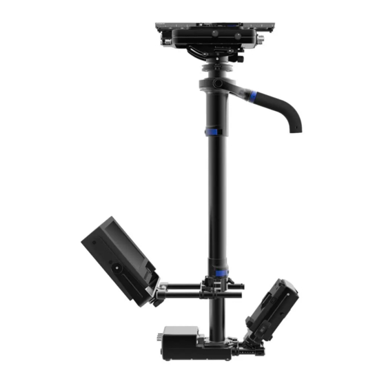
Page 5: System Components
The M-1 System Components The Stage Quick release dovetail Tilt-able to maintain dynamic balance Camera power and video connections The Gimbal Removable handle for future upgrades The Post Modular ends make system maintenance and upgrades quick and painless Carbon fiber posts are indexed to ensure exact alignment... -
Page 6: The Stage
The Stage Dovetail Plate Clamp Lever Maximum rigidity and mounting options Safety latch design with drop-in loading Index marks on side for repeatability Adjustable tension without shims Fore/Aft Drive Knob Fine balance adjustment Side/Side Drive Knob Fine balance adjustment Nose Box Tilt Stage Power and tally ports Dual cam levers to ensure rigidity... - Page 7 Components Fore/Aft Drive Knob Rear Electronics Fine balance adjustment adjustment High-definition video connectors Power ports Side/Side Drive Knob Fine balance adjustment Backlit Bubble Level High precision, spirit level Tilt Drive Knob Easily tilts the camera while the rig is docked or while worn Safety Stops Prevents unintended camera removal...
- Page 8 Provides an isolated port for dedicated accessories Dual 12/24 Volt LEMO 0B Ports High-Definition Video Ports 12 Volts supplied at all times Three direct, 3G compatible connections to the M-1 base 12 and 24 Volts simultaneously when in 24V mode Color-coded at each end...
- Page 9 Components...
- Page 10 Camera Installation: The dovetail lock system was designed to ensure reliable camera safety. Mounting the camera to the M-1 encourages you to keep at least one hand on the camera at all times until it is securely fastened. With your camera mounted to the...
-
Page 11: Camera Installation
The camera and plate can be Close the clamp lever to firmly press the dovetail lock down moved fore and aft for coarse secure the camera onto the M-1. and release the safety latch. balancing, but the safety stops You’ll hear a satisfying click. - Page 12 Camera Removal: As with installing the camera, separating the camera from the M-1 is designed to encourage users to keep at least one hand on the camera at all times. Unlocking the clamp and removing the camera is a quick and easy process that will become second nature in no time.
-
Page 13: Camera Removal
Camera Removal Lift the camera off the rig. Push and hold the safety Keeping the safety latch held to latch to the right. the side, tilt the dovetail plate out of the dovetail lock. Caution: Do not remove safety screws from the dovetail plate or it could slide out if you forget to lock the clamp lever. - Page 14 The Stage Balance Drives: Each knob has a twin on either side of the stage so you can adjust the balance from either side of the rig. With the coarse balancing done and the camera locked in place, fine balancing can be finished with the drives: Fore/aft adjustment knob: turning Side-to-side adjustment knob: Each drive has a scale indicating...
-
Page 15: Drive Mechanisms
Drive Mechanisms Tilt Drive: The tilt drive enables you to easily tilt the camera relative to the post, which allows you to maintain dynamic balance while panning and helps control headroom. It’s also very useful in low mode. The tilt stage offers 15˚ of downward tilt, but if you need to tilt the lens upward, read about the 180˚... - Page 16 Notes...
-
Page 18: The Post
Allows 180˚ reversal The M-1 Post The new modular post for the M-1 system offers maximum rigidity whether it’s built short or at full extension. It also allows users quick access to the stage, gimbal and base components for future upgrades, mods and maintenance. - Page 19 Components Base Connector Electrical and mechanical junction to the base Reference Lines Etched into rear of both posts Confirms perfect alignment Lower Post Lower Post Lower Post Index Groove Ensures alignment of posts Clamp Lever Over-center, tools-free lock Shown here closed...
-
Page 20: 180˚ Post Reversal
The Post 180˚ Post Reversal In some situations you may benefit from having the stage turned to face the other direction; for example, with large camera setups (like 3D) that need additional room directly in front of the stage, or to enable the tilt-head to tilt the lens upward. Without a camera or batteries on Slide the lower post until the Carefully rotate the lower post... - Page 21 180˚ Post Reversal The stage is now turned 180˚ relative to the base. The gimbal post reference line faces forward. Note: Do not operate the M-1 with the red reference line showing!
- Page 22 Notes...
-
Page 24: The Gimbal
The Gimbal Removable Gimbal Handle Pan Bearing Comfortable ergonomic design Inside outer ring Swappable Easy to maintain Dust protected Yoke Clamp Lever Gimbal Grip Over-center, tools-free lock Shown here closed Knurled for positive feel Arm Post Receiver With holes for low-mode bracket... - Page 25 Gimbal Handle Hints: The M-1 gimbal handle is removable. You might want to remove it for shipping, to replace with an accessory, or to adjust the roll bearings. You can also add a low-mode bracket to quickly lower the lens.
- Page 26 Notes...
-
Page 28: The Monitor Mount
The Monitor Mount Clamp Levers Post Clamp Lock or release the monitor rods Hinged quick-release ˚ Opens 180 Post Clamp Knob Knob is captive to the clamp Monitor Rods 15mm by 100mm spacing Industry-standard threaded ends Monitor Yoke Monitor tilts at center of gravity Yokes available for many monitors... - Page 29 Components Safety Release Captive monitor rods Tools-free quick release Upper Post Brake Mount monitor bracket on gimbal post Pivot Clamp Knob Monitor Pivot Adjustable friction brake 180˚of movement for unobstructed views Lower Post Brake Mount monitor bracket on lower post...
- Page 30 Monitor Positioning: The M-1 monitor mount is intended to allow practically limitless mounting positions. The monitor can be positioned close to the post or far away. The mount can attach to either post. The monitor can be tilted to any angle and arced from upright to inverted.
-
Page 31: Monitor Positioning
Note: Tilting the monitor within the monitor yoke does not affect the balance of the M-1 because it spins at the monitor’s center of gravity. Tilting the yoke at the monitor pivot will require rebalancing the rig. - Page 32 The Monitor Mount Reposition the entire assembly. To slide the monitor bracket up or Tighten the post clamp knob to When on the lower post, the down the post, start by supporting lock the monitor mount at the index groove will maintain the monitor and loosening the new position.
- Page 33 The Brakes: Each post on the M-1 has a specific collar, called a brake, for the monitor mount. They are intended to stay on each post to allow for quick repositioning of the monitor from one post to the other. The lower post brake has tabs that align it with the post to ensure the stage, monitor and base stay parallel.
- Page 34 The Monitor Mount Switching Posts: You can easily move the monitor mount from the lower post to the gimbal post. While the mount is off the brake, you can also flip it over so the monitor will be upright in low-mode. Always support the monitor with one hand while disengaging and engaging the clamp.
- Page 35 Monitor Positioning Close the post clamp swing arm around the brake and lock the monitor mount in place with the post clamp knob.
- Page 36 The Monitor Mount Notes...
-
Page 38: The Base And Battery Mount
The Base and Battery Mount Clamp Levers Front Battery Mount Lock or release the battery rods With 12 Volt P-Tap Base Connector Modular mechanical and electronics junction Indexed to ensure exact alignment with post On/Off Switch Power for all components Used for all power ports, with the exception of ISO and battery mount P-Taps Battery Rods... - Page 39 Components 12/24 Volt Switch Select 12 Volt or 24 Volt output when using two or more batteries Base Rear Electronics High-definition video connector Monitor power and tally connector Rear Battery Mount With 12 Volt P-Tap Clamp Knob Locks angle of battery mounts Cheese Plate ¼”...
- Page 40 Power and tally signal Power and tally signal Color-coded at each end coded at each end High-Definition Video Ports Direct, 3G compatible connections to the M-1 stage 12/24 Volt LEDs Color-coded at each end Indicates selected voltage Indicates selected voltage...
- Page 41 Components...
- Page 42 The Base and Battery Mount Battery Positioning: As with the monitor mount, the battery mount gives operators the freedom to set up the rig to their liking. The batteries can be brought in tight to the base for a whippy feel and plenty of leg clearance for switches. The battery mount can also be elongated to increase pan inertia and to balance a monitor placed way out front.
-
Page 43: Battery Positioning
Battery Positioning Slide the batteries to either balance the rig or move to your preferred position. Then re-lock the clamp levers before checking drop time. - Page 44 Notes...
-
Page 46: Power Management And Electronics
The ISO connectors on the stage and the base are isolated from the rest of the power system. There is no power provided from the M-1 batteries and they are not operated via the power switch. The ISO lines are open and available to accommodate the future expansion of your M-1 and custom applications. -
Page 47: Special Notes
Caution about Battery-Mount Video Transmitters: When utilizing 24V mode, do not attach a sandwiched video transmitter to the front battery plate of the M-1. This will cause a live ground situation, damaging the transmitter or other components. Sandwiched transmitters are safe on the rear battery plate in 12V or 24V mode. - Page 48 Power Management and Electronics Nose Box Electronics P-Tap Tally Tally P-Tap Pin 1: PWR GND Pin 1: PWR GND Pin 1: PWR GND Pin 2: +12V Pin 2: TALLY SENSE Pin 2: +12V Pin 3: TALLY OUT Pin 4: +12V 12/24V LEMO 12/24V LEMO 12/24V LEMO...
-
Page 49: Connector Pin Diagrams
Connector/Pin Diagrams Stage, Rear Electronics AMPHENOL® 112253 Pin 1: Pin 1 Base BNC male, direct BNC male, direct Pin 2: Pin 2 Base connect to HD1 on Base connect to HD3 on Base Pin 3: Pin 3 Base Direct connect to ISO on Base CAM PWR BNC male, direct... - Page 50 Power Management and Electronics Base, Front Electronics BNC male, direct BNC male, direct BNC male, direct BNC male, direct Pin 1: Pin 1 Stage connect to HD2 on Stage connect to HD2 on Stage connect to HD3 on Stage connect to HD3 on S connect to HD3 on Stage Pin 2: Pin 2 Stage Pin 3: Pin 3 Stage...
- Page 51 Connector/Pin Diagrams Base, Rear Electronics MON PWR Pin 1: PWR GND BNC male, direct connect Pin 2: +12V to HD1 on Stage Pin 3: TALLY Pin 4: RX Pin 5: TX...
- Page 52 Power Management and Electronics M-1 Stage, Base and Post Connectors: These proprietary connectors carry power and video signals through the post but still allow the components to be disassembled easily. Because these connectors mate together, they are mirrors of each other, so be careful when determining pins.
-
Page 54: Adjustments And Maintenance
Adjustments and Maintenance Separating the Major Modular Components: The three major components—the stage, post and base—all connect through the post connectors. You can easily gain access to your gimbal by removing the stage. Here’s how it works: To remove the stage from the Use a 7/64”... -
Page 55: Separating The Modular Components
Separating Modular Components To reinstall the stage, align the Install the six screws with a 7/64” red dot with the red line on the Allen wrench. Tighten with ample post connectors. Insert firmly until torque to secure the stage. the stainless ring is flush. Caution: Only use the provided high-strength screws for the stage connector. - Page 56 Adjustments and Maintenance To remove the base, start by Use a 9/64” Allen wrench to Pull the post STRAIGHT up off the removing the monitor mount to remove the four screws from base. It may take a firm pull, but make it easier to access the screws.
- Page 57 Separating Modular Components To reinstall the post on the base, Insert firmly until the post align the flat spot on the post connector sits flush on the base connectors. The straight edge of and install the four screws with a the post foot should align behind 9/64”...
- Page 58 Notes...
- Page 60 Adjusting Clamps: The M-1 utilizes a variety of clamps for tools-free adjustments. This section will show you how to ensure each type is adjusted for optimum clamping force and ease of use. When the rig is new, get accustomed to the feel of each mechanism so that you can determine if one needs attention later.
-
Page 61: Clamp Adjustments
Clamp Adjustments Tighten the lock screw. Test to see if the dovetail clamp holds firmly by trying to move the dovetail plate with your hands. Test the clamp lever movement. Repeat adjustment if necessary. - Page 62 Adjustments and Maintenance Tilt Locks: If the brass washers between the tilt stage components have any play when the cam levers are in their closed position, you’re not getting the most rigidity from the system. Here’s how to adjust them properly: Adjust the cam levers while Use an 11/32”...
- Page 63 Clamp Adjustments Check to ensure the cam levers With the levers unlocked, turn the move freely. If they won’t open, tilt drive knob to test that the tilt you’ve over-tightened the nuts. drive system moves smoothly. If it feels right, you’re ready to go.
- Page 64 Adjustments and Maintenance Post Locks: The low-profile post clamps are easy to use and offer a positive lock. You should occasionally test to ensure the gimbal and post are being clamped fully by trying to move the components with the clamps closed. If the components slide with a camera on board, it will affect your drop time.
- Page 65 Clamp Adjustments Rod Clamps: The monitor and battery rod clamp locks are identical. Though the levers only have a short 45˚ throw, they clamp securely when properly adjusted. If they slide with a camera on board it will affect your static balance. Adjust the clamp locks with the Turn the nut a small amount with an Test the holding power of the rod...
- Page 66 Adjustments and Maintenance Hinge Brakes: The monitor and battery pivots have built in friction brakes to support the weight of your monitor and batteries while the clamp knobs are open. If you prefer more or less friction, adjust the friction brakes to your preference. Have your rig completely built and keep one hand on the monitor or batteries while making this adjustment: Adjust the friction hinge with the Use a 7/64”...
- Page 67 Clamp Adjustments...
- Page 68 Adjustments and Maintenance Drive Knob Adjustment: If the fore/aft, side-to-side or tilt drive knobs exhibit free play, your balancing accuracy may be compromised. However, over-tightening can be worse than being loose, so approach these adjustments with care. Follow the steps to tighten the knobs and ensure the proper amount of tension on the drives: Remove the covers on one pair of Loosen the locking set screws...
-
Page 69: Drive Knob Adjustments
Drive Knob Adjustment Tighten the knob on the Tighten the locking set screws The knob should not be opposite side a small amount overly tight, but should not before testing the drive knobs. as well. Adjust the tension a have any slack. When you’re little at a time and sneak up satisfied with the feel of the on the perfect setup. - Page 70 Adjustments and Maintenance Tilt Drive Adjustment: As with the stage drive knobs, the tilt drive knob has an adjustment nut inside. Adjusting it is a similar process: With no camera on the rig, open Use a 1/16” Allen wrench to Use the supplied tool (815-7971) loosen the locking set screw to hand-tighten the nut a small...
- Page 71 Drive Knob Adjustment The drive should have minimal Put the cover back play before engaging, but operate on the tilt drive knob very smoothly. Repeat the and don’t forget to previous steps until you’re close the cam levers. satisfied with the feel.
- Page 72 Notes...
- Page 74 Gimbal Disassembly: The modular nature of the M-1 encourages operators to take good care of their rigs. Cleaning the pan bearing from time to time will keep your M-1 performing at its best. First, remove the gimbal from the post and grab the included blue spanner tool (815-7910).
-
Page 75: Gimbal Disassembly And Cleaning
Gimbal Disassembly and Cleaning Use a 1/16” Allen wrench to remove Use the “outer” spanner pins Applying even pressure to both to unscrew and remove the sides, ease the pan bearing out. the three hex screws and set aside the top cover. pan bearing lock. - Page 76 Adjustments and Maintenance Pan Bearing and Gimbal Housing Cleaning: With the pan bearing removed, spend an adequate amount of time to carefully clean out any contaminants within the pan bearing. Warning: our recommended solvent is 100% acetone; take the necessary precautions to keep it off of sensitive items (such as plastics and your skin) and always follow the manufacturer’s safety recommendations.
- Page 77 Pan Bearing Cleaning Cleaning Steps: In a glass container, put enough 100% acetone to completely cover the bearing and submerge it. Let soak for 10 minutes. Gently agitate the acetone by moving the container or using a paintbrush. ...
- Page 78 Adjustments and Maintenance Gimbal Reassembly: With everything now inspected and cleaned, it’s time to put it all back together. Don’t remember where everything goes? No problem, just follow along: GREASE Lightly grease the inside of the Install the pan bearing lock. Install the top cover with the three outer ring and carefully press in Hand turn first to ensure proper...
-
Page 79: Gimbal Assembly
Gimbal Assembly GREASE If necessary, lightly grease the inner Hold on to the inner ring and screw on the gimbal grip until it’s seated. ring and install with even pressure. Use as little grease as possible to Use the “inner” pins of the spanner to tighten fully. - Page 80 Adjustments and Maintenance Lubricating the M-1: There are a few locations on the rig that can use occasional lubrication. Use a heavy Teflon grease sparingly to keep ® from attracting debris; we recommend Magnalube-G. Areas to Apply Grease: A little grease on the drive gears of the stage will help keep things operating smoothly.
-
Page 81: Lubrication And Exterior Cleaning
Cleaning the M-1: If you’re careful, the 100% acetone used to clean the gimbal is a suitable solvent for cleaning much of the M-1’s carbon fiber, aluminum and stainless steel components. But, if you wish, window cleaner misted onto a lint-free cloth will take care of most grime. -
Page 82: Accessories For The M-1 System
Accessories for the M-1 Accessories: There are many accessories to accommodate the wide variety of operators working with the M-1. From return monitor mounts for the broadcast world to follow focus receiver/amp mounts for cinema ops. Make sure to check out the latest innovations at www.steadicam.com. - Page 83 PART NO. DESCRIPTION 800-7970 1 lb. Weight 815-7905 Docking Collar FFR-000005 Dual Sequential V-Mount Battery Charger FFR-000008 Quad Simultaneous V-Mount Battery Charger FFR-000012 IDX Adapter Bracket FFR-000040 Dual Charger & (2) IDX E-HL9S Batteries FFR-000041 Dual Charger & (4) IDX E-HL9S Batteries FFR-000042 Quad Charger &...
-
Page 84: Contact Tiffen
Contact Tiffen...
Need help?
Do you have a question about the M-1 and is the answer not in the manual?
Questions and answers