Table of Contents
Advertisement
OWNER'S INSTRUCTION MANUAL
It is of vital importance, before attempting to
operate your engine, to read the general
"SAFETY INSTRUCTIONS AND WARNINGS"
section on pages 2-6 of this booklet and to
strictly adhere to the advice contained therein.
•
Also, please study the entire contents of this
instruction manual, so as to familiarize
yourself with the controls and other features
of the engine.
•
Keep these instructions in a safe place so
that you may readily refer to them whenever
necessary.
•
It is suggested that any instructions
supplied with the aircraft, radio control
equipment, etc., are accessible for checking
at the same time.
© Copyright 2003
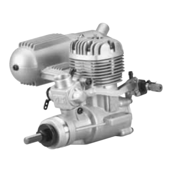
MAX FXi 46
HCAZ3085
Advertisement
Table of Contents

Related Manuals for O.S. engine MAX FXi 46


Summary of Contents for O.S. engine MAX FXi 46
- Page 1 MAX FXi 46 OWNER’S INSTRUCTION MANUAL It is of vital importance, before attempting to operate your engine, to read the general “SAFETY INSTRUCTIONS AND WARNINGS” section on pages 2-6 of this booklet and to strictly adhere to the advice contained therein.
-
Page 2: Table Of Contents
BEFORE STARTING..........13 CONTENTS STARTING ............14 RUNNING-IN (Breaking-in) ........15 SAFETY INSTRUCTIONS AND WARNINGS ABOUT YOUR O.S. ENGINE ........3 NEEDLE VALVE ADJUSTMENT DIAGRAM..17 FEATURES OF FXi SERIES ENGINE ....7 MIXTURE CONTROL VALVE ADJUSTMENT ..19 BEFORE INSTALLING THE ENGINE....7 REALIGNMENT OF MIXTURE CONTROL VALVE ..19 BASIC ENGINE PARTS ........8... -
Page 3: Safety Instructions And Warnings About Your O.s. Engine
If at some future date, your O.S. engine is acquired by another person, we would respectfully request that these instructions are also passed on to its new owner. - Page 4 • Never operate your engine in an WARNINGS! enclosed space. Model engines, like • Never touch, or allow any object to automobile engines, exhaust deadly come into contact with, the rotating propeller and do not crouch over the carbon monoxide. Run your engine only in an open area.
- Page 5 • If you fit a spinner, make sure that it is a your hearing. Such noise is also likely to precision made product and that the cause annoyance to others over a slots for the propeller blades do not cut wide area.
- Page 6 • After starting the engine, carry out any Do not start your engine in an area needle-valve readjustments from a safe containing loose gravel or sand. The position behind the rotating propeller. propeller may throw such material in Stop the engine before attempting to your face and eyes and cause injury.
-
Page 7: Features Of Fxi Series Engine
FEATURES OF FXi SERIES ENGINE BEFORE INSTALLING THE ENGINE This range of engines is ideally suited to a Installing the Glow Plug variety of R/C aircraft, including trainer, Carefully insert plug, with washer, finger sports, acrobatic and scale types. tight only, before final tightening with the correct size plug wrench. -
Page 8: Basic Engine Parts
BASIC ENGINE PARTS INSTALLATION OF THE ENGINE Installation in the Model Make sure that the mounting beams are parallel and that their top surfaces are in the same plane. THROTTLE LINKAGE • Before connecting throttle- lever/servo linkage, make sure that no part of the linkage interferes with the internal structure of the aircraft or wiring, etc., when the throttle is fully... -
Page 9: Muffler
throttle stick fully retarded. Set the exhaust outlet at the required Adjustment of the throttle rotor opening position by rotating the rear part of at the idling position can then be made the silencer. with the throttle trim lever on the Re-tighten assembly screw,... -
Page 10: Glow Plug
tank is 5-10mm (1/4-3/8") above the level of retained within the combustion chamber the needle valve. remains sufficient to keep the plug filament glowing, thereby continuing to keep the Be sure to use a pressurized fuel system by engine running. Ignition timing is "automatic," connecting the muffler pressure nipple to under reduced load, allowing higher RPM, the vent pipe of the fuel tank. -
Page 11: Fuel
When to Replace the Glow Plug For consistent performance and long Apart from when actually burned out, a plug engine life, it is essential to use fuel may need to be replaced because it no containing AT LEAST 18% lubricant by longer delivers its best performance, such volume. -
Page 12: Propellers
Reminder! Model engine fuel is also Reminder! Never touch, or allow any highly flammable. Keep it away from object to come into contact with, the open flame, excessive heat, sources of rotating propeller and do not crouch sparks, or anything else, which might over the engine when it is running. -
Page 13: Before Starting
approximate best result. First run the dry cell, or preferably, a 2-volt rechargeable engine as received and readjust the Mixture lead-acid cell. Control Screw only if necessary. Warning (Very hot): Never touch the nichrome wire while battery BEFORE STARTING connected. Tools, Accessories, etc. -
Page 14: Starting
to transfer fuel directly from your fuel STARTING container to the fuel tank. 8–Electric Starter and Starter Battery Install appropriate propeller and tighten An electric starter is recommended for securely. starting. To facilitate electric starting, install an O.S. solid aluminum alloy spinner-nut for 9–Fuel Can Filter centering the rubber drive insert of the Fit a filter to the outlet tube of your refueling... -
Page 15: Running-In (Breaking-In)
Open the throttle approx. one-quarter. otherwise there is a danger of it becoming Connect battery leads to glow plug. overheated and damaged. Bring electric starter into contact with spinner-nut or spinner and depress starter switch for one or two seconds. RUNNING-IN (“Breaking-In”) Repeat if necessary. - Page 16 installed in the model. The process is cycle" from "four-cycle" operation, then as follows: make three or four flights, avoiding successive "nose-up" flights. During subsequent flights, the needle Install the engine with the propeller valve can be gradually closed to give intended for your model.
-
Page 17: Needle Valve Adjustment Diagram
disconnect the battery from the glow plug, NEEDLE-VALVE ADJUSTMENT DIAGRAM taking care that the battery leads or glow plug clip do not come into contact with the rotating propeller. If the engine stops when Note: This diagram is for reference the battery is disconnected, close the purposes only. -
Page 19: Mixture Control Valve Adjustment
positively enrich the idle mixture, then turn the screw clockwise gradually until the MIXTURE CONTROL VALVE engine regains full power cleanly when the ADJUSTMENT throttle is reopened. With the engine running, close the throttle Carry out adjustments patiently until the and allow it to idle for about five seconds, engine responds quickly and positively to and then open the throttle fully. -
Page 20: Subsequent Starting Procedure
basic setting can be re-established as starts, reopen the throttle and re-adjust the follows: Close the throttle rotor gradually needle valve to the optimum setting. from the fully opened position until it is just fully closed. (Do not turn further.) Then, Note: When re-starting the engine on the screw in the Mixture Control Screw until it same day, provided that atmospheric... -
Page 21: Carburetor Cleanliness
for some readjustment of the Needle-Valve. O.S. Super-Filters (large and small) are Remember that, as a safety measure, it is available, as optional extras, to deal with advisable to increase the Needle-Valve this problem. opening extra half-turn counterclockwise, prior to establishing a One of these filters, fitted to the outlet tube new setting. -
Page 22: Engine Care & Maintenance
These procedures will reduce the risk of ENGINE CARE & MAINTENANCE starting difficulties and of internal corrosion after a period of storage. At the end of each operating session, drain out any fuel that may remain in the fuel tank. O.S. - Page 23 UPS or insured Parcel Post to our national servicing facility: Hobby Services 3002 N. Apollo Dr., Suite 1 Champaign, IL 61821 (217) 398-0007 Along with Your engine and proof of purchase date please enclose a complete written explanation detailing the problems. State your name and address clearly.
-
Page 26: Carburetor Exploded View
CARBURETOR EXPLODED VIEW CARBURETOR PARTS LIST Code No. Description 22781401 Throttle Lever Assembly 22781411 Throttle Lever 22781420 Throttle Lever Screw 27783600 Mixture Control Valve 22781800 O-ring 25681200 Carburetor Rotor 26781506 Rotor Spring 25681100 Carburetor Body 25681620 Throttle Stop Screw 22681953 Fuel Inlet (No.
Need help?
Do you have a question about the MAX FXi 46 and is the answer not in the manual?
Questions and answers