Table of Contents
Advertisement
Safety Depends on You
Lincoln arc welding and cutting
equipment is designed and built
with safety in mind. However, your
overall safety can be increased by
proper installation ... and thought-
ful operation on your part. DO
NOT INSTALL, OPERATE OR
REPAIR THIS EQUIPMENT
WITHOUT
READING
MANUAL AND THE SAFETY
PRECAUTIONS CONTAINED
THROUGHOUT. And, most
importantly, think before you act
and be careful.
ISO 9001
ANSI RAB
QMS
Designed and Manufactured Under a
Quality Program Certified by
ABS Quality Evaluations, Inc.
to ISO 9001 Requirements.
CERTIFICATE NUMBER: 30273
• Sales and Service through Subsidiaries and Distributors Worldwide •
Cleveland, Ohio 44117-1199 U.S.A. TEL: 216.481.8100 FAX: 216.486.1751 WEB SITE: www.lincolnelectric.com
RETURN TO MAIN MENU
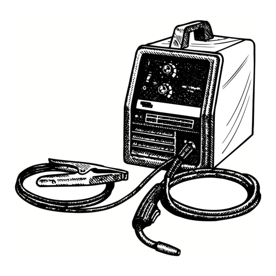
Pro-MIG 175
For use with machine Code Numbers 11009
THIS
OPERATOR'S MANUAL
• World's Leader in Welding and Cutting Products •
Copyright © 2005 Lincoln Global Inc.
IM810
July, 2005
Advertisement
Table of Contents

Related Manuals for Lincoln Electric PRO-MIG 175 IM810


Summary of Contents for Lincoln Electric PRO-MIG 175 IM810
- Page 1 Pro-MIG 175 For use with machine Code Numbers 11009 Safety Depends on You Lincoln arc welding and cutting equipment is designed and built with safety in mind. However, your overall safety can be increased by proper installation ... and thought- ful operation on your part.
-
Page 2: California Proposition 65 Warnings
351040, Miami, Florida 33135 or CSA Standard W117.2-1974. A Free copy of “Arc Welding Safety” booklet E205 is available from the Lincoln Electric Company, 22801 St. Clair Avenue, Cleveland, Ohio 44117-1199. BE SURE THAT ALL INSTALLATION, OPERATION, MAINTENANCE AND REPAIR PROCEDURES ARE PERFORMED ONLY BY QUALIFIED INDIVIDUALS. -
Page 3: Electric Shock Can Kill
ELECTRIC SHOCK can kill. 3.a. The electrode and work (or ground) circuits are electrically “hot” when the welder is on. Do not touch these “hot” parts with your bare skin or wet clothing. Wear dry, hole-free gloves to insulate hands. - Page 4 WELDING SPARKS can cause fire or explosion. 6.a. Remove fire hazards from the welding area. If this is not possible, cover them to prevent the welding sparks from starting a fire. Remember that welding sparks and hot materials from welding can easily go through small cracks and openings to adjacent areas.
- Page 5 PRÉCAUTIONS DE SÛRETÉ Pour votre propre protection lire et observer toutes les instructions et les précautions de sûreté specifiques qui parraissent dans ce manuel aussi bien que les précautions de sûreté générales suiv- antes: Sûreté Pour Soudage A L’Arc 1. Protegez-vous contre la secousse électrique: a.
- Page 6 The code number is especially important when identifying the correct replacement parts. - Register your machine with Lincoln Electric either via fax or over the Internet. • For faxing: Complete the form on the back of the warranty statement included in the literature packet accompanying this machine and fax the form per the instructions printed on it.
-
Page 7: Table Of Contents
Installation ...Section A Technical Specifications ...A-1 Safety Precautions...A-2 Identify and Locate Components ...A-2 Select Suitable Location ...A-3 Output Connections ...A-3 Work Clamp Installation ...A-3 Work Cable Installation ...A-3 Gun Installation...A-4 Gas Connection ...A-5 Input Connections...A-6 Line Cord Connection ...A-6 230 Volt Input Connection ...A-6 208 Volt Input Connection ...A-6 Operation ...Section B Safety Precautions ...B-1... -
Page 8: Installation
TECHNICAL SPECIFICATIONS – Pro-MIG 175 Standard Voltage/Frequency 230V/60Hz 208V/60Hz Duty Cycle 30% Duty Cycle @ 230V/60Hz 25% Duty Cycle @ 208V/60Hz Welding Current Range Rated DC Output: 30 – 175 amps RECOMMENDED INPUT CABLE AND FUSE SIZES Output Mode Input Voltage RATED 230V/60Hz 208V/60Hz... -
Page 9: Safety Precautions
SAFETY PRECAUTIONS Read entire installation section before starting installation. WARNING ELECTRIC SHOCK can kill. • Only qualified personnel should perform this installation. • Only personnel that have read and under- stood the PRO-MIG 175 Operating Manual should install and operate this equipment. •... -
Page 10: Select Suitable Location
SELECT SUITABLE LOCATION Locate the welder in a dry location where there is free circulation of clean air into the louvers in the back and out the front of the unit. A location that minimizes the amount of smoke and dirt drawn into the rear louvers reduces the chance of dirt accumulation that can block air passages and cause overheating. -
Page 11: Work Cable Installation
Work Cable Installation Refer to Figure A.2. 1. Open the wire feed section door on the right side of the Pro-MIG 175. 2. Pass the end of the work cable that has the termi- nal lug with the smaller hole through the Work Cable Access Hole (1) in the case front. -
Page 12: Input Connections
Keep cylinder upright and chained to support • Keep cylinder away from areas where it may be damaged. • Never lift welder with cylinder attached. • Never allow welding electrode to touch cylinder. • Keep cylinder away from welding or other live electrical circuits. -
Page 13: Input Connections
230 Volt Input Connection The Pro-MIG 175 is shipped from the factory connect- ed for 230 volt input power. If the welder has been reconnected for 208 volt input power and 230 volt input is desired, perform the following reconnection... -
Page 14: Saftey Precautions
OPERATION GENERAL DESCRIPTION The Pro-MIG 175 is a complete semiautomatic con- stant voltage DC portable arc welder. Included is a tap-switch controlled, single phase constant voltage transformer/rectifier power source and a wire feeder with welding gun for feeding .023" (0.6 mm) through .030"... -
Page 15: Welding Capability
No external shielding gas is required when used with Lincol .035” (0.9 mm) Innershield NR MP electrode. Spindle accommodates both 8 in. (200 mm) diame- ter and 4 in. (100 mm) diameter spools of wire. WELDING CAPABILITY The Pro-MIG 175 is rated at 130 amps, 20 volts, at 30% duty cycle on a ten minute basis. -
Page 16: Welding Operations
WELDING OPERATIONS SEQUENCE OF OPERATION Wire Loading Refer to Figure B.2 and B.3. The machine power switch should be turned to the OFF (“O”) position before working inside the wire feed enclosure. The machine is shipped from the factory ready to feed 8”... -
Page 17: Wire Threading
Wire Threading Refer to Figure B.4 1. Release the Spring Loaded Pressure Arm (1) rotate the Idle Roll Arm (2) away from the Wire Feed Drive Roll (3). Ensure that the groove size in the feeding position on the drive roll matches the wire size being used. -
Page 18: Making A Weld
FIGURE B.6 Contact Tip Wire Electrode 3/8"– 1/2"(10-13mm) Contact Tip to Work Distance(CTWD) Making A Weld 1. See “Process Guidelines” in this section for selec- tion of welding wire and shielding gas and for range of metal thicknesses that can be welded. 2. -
Page 19: Changing Machine Over To Feed Other Wire Sizes
The Pro-MIG 175 is suitable for .035" aluminum wire and .023"– .035" stainless wire. Refer to Table B.1 for recommended procedure settings. (Requires K586-1 regulator kit and K664-2 Aluminum - Stainless Feeding Kit.) CAUTION It is important when changing between welding with steel wire and aluminum to exchange feeding components due to the lubricant applied to steel wire. -
Page 20: Application Chart
APPLICATION CHART Pro-MIG 175... -
Page 21: Optional Accessories
OPTIONAL ACCESSORIES 1. K549-1 .035" (0.9 mm) Innershield® Welding Kit — Includes a contact tip, a gasless nozzle and a .030/.035 (.8/.9mm) cable liner to permit the Magnum™ 100L gun and cable to use .035" (0.9 mm) diameter flux-cored electrode. The fitting on the end of the liner is stenciled with the maximum rated wire size (.045"/1.2 mm). -
Page 22: Innershield (Fcaw) Conversion
INNERSHIELD (FCAW) CONVERSION Several changes are needed to convert the unit for operation with the Innershield (FCAW) process. The K549-1 Innershield Kit includes all the necessary accessories for this conversion and is provided for this purpose. The following conversions should be made using the contents of this kit: 1. -
Page 23: Maintenance
POWER SOURCE COMPARTMENT In extremely dusty locations, dirt may clog the air passages causing the welder to run hot. Blow dirt out of the welder with low pressure air at regular intervals to eliminate excessive dirt and dust build-up on interval parts. -
Page 24: Gun And Cable Maintenance
GUN AND CABLE MAINTENANCE FOR MAGNUM™ 100L GUN Gun Cable Cleaning Clean cable liner after using approximately 300 lbs (136 kg) of solid wire or 50 lbs (23 kg) of flux-cored wire. Remove the cable from the wire feeder and lay it out straight on the floor. -
Page 25: Component Replacement Procedures
COMPONENT REPLACEMENT PROCEDURES CHANGING THE CONTACT TIP 1. Refer to Figure D.2. Remove the gas nozzle from the gun by unscrewing counter-clockwise. 2. Remove the existing contact tip from the gun by unscrewing counter-clockwise. 3. Insert and hand tighten desired contact tip. 4. -
Page 26: Changing Liner
Set Screw Brass Cable Connector Liner Assembly (Liner bushing to be sealed tight against brass cable connector) FIGURE D.2 Liner trim length CHANGING LINER NOTICE: The variation in cable lengths prevents the interchangeability of liners. Once a liner has been cut for a particular gun, it should not be installed in anoth- er gun unless it can meet the liner cutoff length requirement. -
Page 27: Troubleshooting
HOW TO USE TROUBLESHOOTING GUIDE Service and Repair should only be performed by Lincoln Electric Factory Trained Personnel. Unauthorized repairs performed on this equipment may result in danger to the technician and machine operator and will invalidate your factory warranty. For your safety and to avoid Electrical Shock, please observe all safety notes and precautions detailed throughout this manual. - Page 28 Fan operates normally. If for any reason you do not understand the test procedures or are unable to perform the tests/repairs safely, contact your LOCAL AUTHORIZED LINCOLN ELECTRIC FIELD SERVICE FACILITY for assistance before you proceed. TROUBLESHOOTING POSSIBLE...
- Page 29 If for any reason you do not understand the test procedures or are unable to perform the tests/repairs safely, contact your LOCAL AUTHORIZED LINCOLN ELECTRIC FIELD SERVICE FACILITY for assistance before you proceed. TROUBLESHOOTING POSSIBLE...
- Page 30 Arc is unstable – Poor starting If for any reason you do not understand the test procedures or are unable to perform the tests/repairs safely, contact your LOCAL AUTHORIZED LINCOLN ELECTRIC FIELD SERVICE FACILITY for assistance before you proceed. TROUBLESHOOTING...
-
Page 31: Wiring Diagrams
WIRING DIAGRAMS NOTE: This diagram is for reference only. It may not be accurate for all machines covered by this manual. The specific diagram for a particular code is pasted inside the machine on one of the enclosure panels. Pro-MIG 175... - Page 32 NOTES...
- Page 33 NOTES...
- Page 34 WARNING Spanish AVISO DE PRECAUCION French ATTENTION German WARNUNG Portuguese ATENÇÃO Japanese Chinese Korean Arabic READ AND UNDERSTAND THE MANUFACTURER’S INSTRUCTION FOR THIS EQUIPMENT AND THE CONSUMABLES TO BE USED AND FOLLOW YOUR EMPLOYER’S SAFETY PRACTICES. SE RECOMIENDA LEER Y ENTENDER LAS INSTRUCCIONES DEL FABRICANTE PARA EL USO DE ESTE EQUIPO Y LOS CONSUMIBLES QUE VA A UTILIZAR, SIGA LAS MEDIDAS DE SEGURIDAD DE SU SUPERVISOR.
- Page 35 Keep your head out of fumes. Turn power off before servicing. Use ventilation or exhaust to remove fumes from breathing zone. Los humos fuera de la zona de res- Desconectar el cable de ali- piración. mentación de poder de la máquina Mantenga la cabeza fuera de los antes de iniciar cualquier servicio.
- Page 36 • World's Leader in Welding and Cutting Products • • Sales and Service through Subsidiaries and Distributors Worldwide • Cleveland, Ohio 44117-1199 U.S.A. TEL: 216.481.8100 FAX: 216.486.1751 WEB SITE: www.lincolnelectric.com...
Need help?
Do you have a question about the PRO-MIG 175 IM810 and is the answer not in the manual?
Questions and answers