Table of Contents
Advertisement
RETURN TO MAIN MENU
IM972
OUTBACK
185
™
September, 2010
11516
For use with machines having Code Numbers:
Safety Depends on You
Lincoln arc welding and cutting
equipment is designed and built
with safety in mind. However,
your overall safety can be
increased by proper installation
... and thoughtful operation on
your part. DO NOT INSTALL,
OPERATE OR REPAIR THIS
EQUIPMENT WITHOUT READ-
ING THIS MANUAL AND THE
SAFETY PRECAUTIONS CON-
TAINED THROUGHOUT. And,
most importantly, think before
you act and be careful.
OPERATORʼS MANUAL
Copyright © Lincoln Global Inc.
®
• World's Leader in Welding and Cutting Products •
• Sales and Service through Subsidiaries and Distributors Worldwide •
Cleveland, Ohio 44117-1199 U.S.A. TEL: 216.481.8100 FAX: 216.486.1751 WEB SITE: www.lincolnelectric.com
Advertisement
Table of Contents

Related Manuals for Lincoln Electric OUTBACK 185 IM972


Summary of Contents for Lincoln Electric OUTBACK 185 IM972
- Page 1 RETURN TO MAIN MENU IM972 OUTBACK ™ September, 2010 11516 For use with machines having Code Numbers: Safety Depends on You Lincoln arc welding and cutting equipment is designed and built with safety in mind. However, your overall safety can be increased by proper installation ...
-
Page 2: Electric And Magnetic Fields
351040, Miami, Florida 33135 or CSA Standard W117.2-1974. A Free copy of “Arc Welding Safety” booklet E205 is available from the Lincoln Electric Company, 22801 St. Clair Avenue, Cleveland, Ohio 44117-1199. BE SURE THAT ALL INSTALLATION, OPERATION, MAINTENANCE AND REPAIR PROCEDURES ARE PERFORMED ONLY BY QUALIFIED INDIVIDUALS. -
Page 3: Electric Shock Can Kill
ELECTRIC SHOCK can kill. 3.a. The electrode and work (or ground) circuits are electrically “hot” when the welder is on. Do not touch these “hot” parts with your bare skin or wet clothing. Wear dry, hole-free gloves to insulate hands. - Page 4 WELDING and CUTTING SPARKS can cause fire or explosion. 6.a. Remove fire hazards from the welding area. If this is not possible, cover them to prevent the welding sparks from starting a fire. Remember that welding materials from welding can easily go through small cracks and openings to adjacent areas.
- Page 5 PRÉCAUTIONS DE SÛRETÉ Pour votre propre protection lire et observer toutes les instructions et les précautions de sûreté specifiques qui parraissent dans ce manuel aussi bien que les précautions de sûreté générales suiv- antes: Sûreté Pour Soudage A LʼArc 1. Protegez-vous contre la secousse électrique: a.
- Page 6 Electric for advice or information about their use of our products. We respond to our customers based on the best information in our posses- sion at that time. Lincoln Electric is not in a position to warrant or guarantee such advice, and assumes no liability, with respect to such infor- mation or advice.
-
Page 7: Table Of Contents
General Description...B-3 Recommended Applications...B-3 Operational Features and Controls ...B-3 Design Features and Advantages ...B-3 Welding Capability...B-3 Limitations ...B-3 Controls and Settings ...B-4 Welder/Generator Controls ...B-4 Engine Operation ...B-5 Welding Operation...B-6 Auxiliary Power...B-7 Electrode selection Guide ...B-7 Auxiliary Power Application ...B-8 ________________________________________________________________________________ Accessories ...Section C... -
Page 8: Installation
4 cycle air-cooled OHV gasoline 12.75 HP @ 3600 RPM Aluminum Block w/ Cast Iron Sleeve AMPS @ DC CONSTANT CURRENT OUTPUT -WELDER AND GENERATOR Welding Ranges 50 - 185 Amps DC HEIGHT WIDTH 25.47 in. 21.12 in. 646.94 mm 536.45 mm... -
Page 9: Safety Precautions
SAFETY PRECAUTIONS Read this entire installation section before you start installation. WARNING Do not attempt to use this equipment until you have thoroughly read all operating and mainte- nance manuals supplied with your machine. They include important safety precautions, detailed engine starting, operating and maintenance instructions, and parts lists. -
Page 10: Stacking
STACKING OUTBACK™ 185 machines CANNOT be stacked. TILTING Place the machine on a secure, level surface whenev- er you use it or store it. Any surfaces you place it on other than the ground must be firm, non-skid, and structurally sound. The gasoline engine is designed to run in a level posi- tion for best performance. -
Page 11: Electrical Output Connections
Table A.1 lists recommended cable sizes and lengths for rated current and duty cycle. Length refers to the distance from the welder to the work and back to the welder. Cable diameters are increased for long cable lengths to reduce voltage drops. -
Page 12: Machine Grounding
• Do not cross welding cables at output stud connec- tion. Keep isolated and separate from one another. ------------------------------------------------------------------------ Lincoln Electric offers a welding accessory kit with #6 welding cables. See the ACCESSORIES section of this manual for more information. -
Page 13: Plugs And Hand Held Equipment
PLUGS AND HAND HELD EQUIPMENT For further protection against electric shock, any elec- trical equipment connected to the generator recepta- cles must use a three-blade, grounded type plug or an Underwriterʼs Laboratories (UL) approved double insulated tool with a two blade plug. WARNING Never operate this machine with damaged or defective cords. -
Page 14: Electrical Devices Used With The Outback™ 185
Capacitive / Inductive Computers, high resolution TV sets, complicated electrical equipment. The Lincoln Electric Company is not responsible for any damage to electrical components improperly connected to a OUTBACK™ 185. INSTALLATION CAUTION TABLE A.2 Possible Concerns... -
Page 15: Operation
SAFETY INSTRUCTIONS WARNING ELECTRIC SHOCK can kill. • Do not touch electrically live parts or electrode with skin or wet clothing. • Insulate yourself from work and ground. • Always wear dry insulating gloves. FUMES AND GASES can be dangerous. •... -
Page 16: Symbols
GRAPHIC SYMBOLS USED ON THIS EQUIPMENT OR IN THIS MANUAL WARNING / CAUTION FUEL WORK CLAMP FAST SLOW AUTO IDLE OPERATION OUTBACK™ 185 ® CHOKE AIR CLEANER CIRCUIT BREAKER GROUND (AUXILIARY POWER) ELECTRODE WELDING ARC ENGINE OFF ENGINE START... -
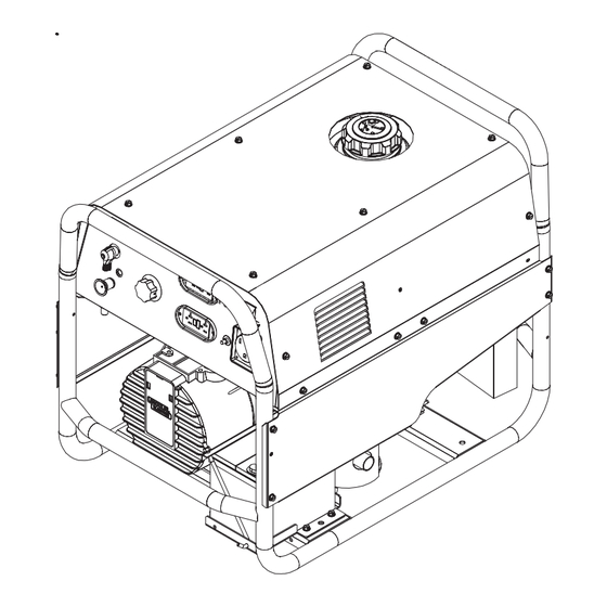
Page 17: General Description
The OUTBACK™ 185 rated 185 amps, 20 VDC at 10% duty cycle on a ten-minute basis. This means that you can load the welder to 185 amps for one minute out of every ten-minute period. The machine is capable of higher duty cycles at lower output cur- rents. -
Page 18: Controls And Settings
9. 120 VOLT DUPLEX RECEPTACLES (2): Connection point for supplying 120 volt power to operate devices needed for maintenance purposes. OPERATION All welder/generator controls are located on the Output Control Panel. OUTPUT PANEL CONTROLS 3 or 4 FIGURE B.1 10. HOUR METER: Records the time that the engine has run for maintenance purposes. -
Page 19: Engine Operation
ENGINE OPERATION Starting/Shutdown Instructions Be sure all Pre-Operation Engine Service has been performed. Also, Read owners manual before starting for the first time. (See INSTALLATION section) Remove all loads connected to the AC power recepta- cles. Before starting, first open the fuel shutoff valve. Always pull the choke control out when starting the engine;... -
Page 20: Welding Operation
The OUTBACK™ 185 generator power can be used to supply up to 5,200 watts continuous input power to a Lincoln Wire Feeder/Welder. The Wire Feeder/ Welder is equipped with all the supplies needed for Flux-Cored Arc Welding (FCAW). Also some Wire Feeder/Welders come... -
Page 21: Auxiliary Power
120V Receptacle Operation: • Set the Output Control on the Pro-Cut 25 no higher than the 15 amp position.( Higher settings may cause circuit breaker on the OUTBACK™ 185 to trip.) • Maximum material thickness that can be cut is 1/4". 240V Receptacle Operation: •... -
Page 22: Auxiliary Power Application
*Submersible Pump - 1 HP *Sump Pump Toaster Weed Trimmer Lincoln Wire Feeder/Welder NOTES: Wattages listed are approximate. Check your equipment for actual wattage. Equipment with unusually high *START-UP WATTS are listed. For start-up of other equipment that uses a motor, listed in the table, multiply RUNNING WATTS by 2. -
Page 23: Accessories
OPTIONS/ACCESSORIES The following options/accessories are available for your OUTBACK™185 from your local Lincoln Distributor: Accessory Kit (K875) – Includes the following: • Twenty feet (6.1 meters) of #6 AWG electrode cable with lug. • Fifteen feet (4.6 meters) of #6 work cable with lugs. •... -
Page 24: Maintenance
SAFETY PRECAUTIONS WARNING • Have qualified personnel do all maintenance and troubleshooting work. • Turn the engine off before working inside the machine. • Remove guards only when necessary to perform maintenance and replace them when the mainte- nance requiring their removal is complete. •... - Page 25 Do not attempt to polish slip rings while engine is running. ------------------------------------------------------------------------ HARDWARE Both English and Metric fasteners are used in this welder. ENGINE MAINTENANCE PARTS Kohler CS 12.75 Air Filter Element Air Filter Pre-Cleaner Spark Plug...
-
Page 26: Troubleshooting
HOW TO USE TROUBLESHOOTING GUIDE Service and Repair should only be performed by Lincoln Electric Factory Trained Personnel. Unauthorized repairs performed on this equipment may result in danger to the technician and machine operator and will invalidate your factory warranty. For your safety and to avoid Electrical Shock, please observe all safety notes and precautions detailed throughout this manual. - Page 27 Observe all Safety Guidelines detailed throughout this manual PROBLEMS (SYMPTOMS) Major Physical or Electrical Damage is Evident. No Generator power or welding output Generator power is available but unit will not weld. Unit will weld but low or no generator power is available. No auxillary power but machine has weld output.
- Page 28 CAUSE ENGINE PROBLEMS 1. Engine Switch on HIGH Idle. 2. Engine choke is not fully open. 3. External load on welder or auxiliary power. - Remove load. 4. Machine output is under load or Engine switch in wrong position. 5. Idle solenoid does not pull in.
- Page 29 Observe all Safety Guidelines detailed throughout this manual PROBLEMS (SYMPTOMS) Engine runs erratically or stops running. Engine sputters but will not start. Recoil starter is hard to pull. Arc is erratic and “pops out”. Arc becomes “Cold” at the short Arc lenghts or shorts to the work piece.
- Page 30 DIAGRAMS OUTBACK™ 185 ®...
-
Page 31: Dimension Print
DIMENSION PRINT OUTBACK™ 185 ®... - Page 32 NOTES OUTBACK™ 185 ®...
- Page 33 WARNING Spanish AVISO DE PRECAUCION French ATTENTION German WARNUNG Portuguese ATENÇÃO Japanese Chinese Korean Arabic READ AND UNDERSTAND THE MANUFACTURERʼS INSTRUCTION FOR THIS EQUIPMENT AND THE CONSUMABLES TO BE USED AND FOLLOW YOUR EMPLOYERʼS SAFETY PRACTICES. SE RECOMIENDA LEER Y ENTENDER LAS INSTRUCCIONES DEL FABRICANTE PARA EL USO DE ESTE EQUIPO Y LOS CONSUMIBLES QUE VA A UTILIZAR, SIGA LAS MEDIDAS DE SEGURIDAD DE SU SUPERVISOR.
- Page 34 Keep your head out of fumes. Turn power off before servic- Use ventilation or exhaust to ing. remove fumes from breathing zone. Los humos fuera de la zona de Desconectar el cable de ali- respiración. mentación de poder de la Mantenga la cabeza fuera de máquina antes de iniciar los humos.
- Page 35 ® • World's Leader in Welding and Cutting Products • • Sales and Service through Subsidiaries and Distributors Worldwide • Cleveland, Ohio 44117-1199 U.S.A. TEL: 216.481.8100 FAX: 216.486.1751 WEB SITE: www.lincolnelectric.com...
Need help?
Do you have a question about the OUTBACK 185 IM972 and is the answer not in the manual?
Questions and answers