Table of Contents
Troubleshooting

Related Manuals for Miller Bobcat 225 NT


Summary of Contents for Miller Bobcat 225 NT
- Page 1 OM-405 184 289K January 2000 Processes Stick (SMAW) Welding MIG (GMAW) Welding Flux Cored (FCAW) Welding Non-Critical TIG (GTAW) Welding Description Engine Driven Welding Generator Bobcat 225 NT Visit our website at www.MillerWelds.com...
- Page 2 – every power source from This Owner’s Manual is designed to help you get the most out of your Miller is backed by the most Miller products. Please take time to read the Safety precautions. They will hassle-free warranty in the business.
-
Page 3: Table Of Contents
TABLE OF CONTENTS SECTION 1 – SAFETY PRECAUTIONS - READ BEFORE USING ......1-1. Symbol Usage . -
Page 5: Section 1 - Safety Precautions - Read Before Using
SECTION 1 – SAFETY PRECAUTIONS - READ BEFORE USING rom _nd_11/98 1-1. Symbol Usage Means Warning! Watch Out! There are possible hazards with this procedure! The possible hazards are shown in the adjoining symbols. This group of symbols means Warning! Watch Out! possible Y Marks a special safety message. -
Page 6: Engine Hazards
WELDING can cause fire or explo- HOT PARTS can cause severe burns. sion. D Allow cooling period before maintaining. Welding on closed containers, such as tanks, D Wear protective gloves and clothing when drums, or pipes, can cause them to blow up. Sparks working on a hot engine. -
Page 7: Additional Symbols For Installation, Operation, And Maintenance
READ INSTRUCTIONS. stopping engine. D Do not let low voltage and frequency caused by D Use only genuine MILLER replacement parts. low engine speed damage electric motors. D Perform engine maintenance and service D Do not connect 50 or 60 Hertz motors to the 100 Hertz receptacle according to this manual and the engine where applicable. -
Page 8: Principal Safety Standards
H.F. RADIATION can cause interference. ARC WELDING can cause interference. D High-frequency (H.F.) can interfere with radio D Electromagnetic energy can interfere with navigation, safety services, computers, and sensitive electronic equipment such as communications equipment. computers and computer-driven equipment D Have only qualified persons familiar with such as robots. -
Page 9: Section 1 - Consignes De Sécurité - Lire Avant Utilisation
SECTION 1 – CONSIGNES DE SÉCURITÉ – LIRE AVANT UTILISATION rom _nd_fre 11/98 1-1. Signification des symboles Signifie Mise en garde ! Soyez vigilant ! Cette procédure présente des risques de danger ! Ceux-ci sont identifiés par des symboles adjacents aux directives. Ce groupe de symboles signifie Mise en garde ! Soyez vigilant ! Il y a des Y Identifie un message de sécurité... -
Page 10: Dangers Existant En Relation Avec Le Moteur
LE SOUDAGE peut provoquer un in- DES PIÈCES CHAUDES peuvent cendie ou une explosion. provoquer des brûlures graves. D Prévoir une période de refroidissement avant d’effec- Le soudage effectué sur des conteneurs fermés tels que tuer des travaux d’entretien. des réservoirs, tambours ou des conduites peut provoquer D Porter des gants et des vêtements de protection pour leur éclatement. -
Page 11: Dangers Supplémentaires En Relation Avec L'installation, Le Fonctionnement Et La Maintenance
DES ORGANES MOBILES peuvent L’ACIDE DE LA BATTERIE peut pro- provoquer des blessures. voquer des brûlures dans les YEUX et sur la PEAU. D Ne pas approcher les mains des ventilateurs, cour- roies et autres pièces en mouvement. D Ne pas renverser la batterie. D Maintenir fermés et fixement en place les portes, D Remplacer une batterie endommagée. -
Page 12: Principales Normes De Sécurité
LE RAYONNEMENT HAUTE FRÉ- LE SOUDAGE À L’ARC risque de QUENCE (H.F.) risque de provoquer provoquer des interférences. des interférences. D L’énergie électromagnétique risque de provoquer des interférences pour l’équipement électronique D Le rayonnement haute fréquence (H.F.) peut sensible tel que les ordinateurs et l’équipement com- provoquer des interférences avec les équipements mandé... -
Page 13: Section 2 - Definitions
SECTION 2 – DEFINITIONS 2-1. Symbol Definitions Fast Fast/Slow Stop Engine Slow (Idle) (Run, Weld/Power) (Run/Idle) Read Operator’s Start Engine Amperes Volts Manual Engine Oil Fuel Battery (Engine) Engine Check Valve Do not switch while Engine Choke Work Connection Clearance welding Alternating Current Positive... -
Page 14: Dimensions, Weights, And Operating Angles
3-2. Dimensions, Weights, and Operating Angles Dimensions Height 33-1/2 in (851 mm) Width 18-3/4 in (476 mm) Y Do not exceed tilt angles or engine could Depth 46 in (1164 mm) be damaged or unit could tip. 18 in (457 mm) Y Do not move or operate unit where it could tip. -
Page 15: Fuel Consumption (Onan-Powered Units)
3-4. Fuel Consumption (Onan-Powered Units) SB-119 455-A 3-5. Fuel Consumption (Kohler-Powered Units) SB-179 939 OM-405 Page 11... -
Page 16: Duty Cycle
3-6. Duty Cycle Duty cycle is the percentage of 10 minutes that unit can weld at rated load without overheating. Y Exceeding duty cycle can damage unit void warranty. Continuous Welding 100% Duty Cycle at 225 Amperes CC/AC, 210 Amperes CC/DC, 200 Amperes CV/DC SB-119 454-A 3-7. -
Page 17: Section 4 - Installation
SECTION 4 – INSTALLATION 4-1. Installing Welding Generator Y Do not weld on base. Weld- ing on base can cause fuel tank fire or explosion. Bolt unit down using holes pro- Movement Airflow Clearance vided in base. Y Always ground generator Y Do not lift unit from end. -
Page 18: Engine Prestart Checks (Onan-Powered Units)
4-2. Engine Prestart Checks (Onan-Powered Units) Check all fluids daily. Engine must be cold and on a level surface. Unit is shipped with 10W30 engine oil. Full Follow run-in procedure in en- gine manual. This unit has a low oil pressure Gasoline shutdown switch. -
Page 19: Engine Prestart Checks (Kohler-Powered Units)
4-3. Engine Prestart Checks (Kohler-Powered Units) Check all fluids daily. Engine must be cold and on a level surface. Unit is shipped with 10W30 engine oil. Full Follow run-in procedure in en- gine manual. This unit has a low oil pressure shutdown switch. -
Page 20: Activating The Dry Charge Battery (If Applicable)
4-4. Activating The Dry Charge Battery (If Applicable) Remove battery from unit. Eye Protection – Safety Glasses Or Face Shield Rubber Gloves Vent Caps Sulfuric Acid Electrolyte (1.265 Specific Gravity) Well Fill each cell with electrolyte to bottom of well (maximum). Y Do not overfill battery cells. -
Page 21: Connecting The Battery
4-5. Connecting the Battery Y Connect negative (–) cable last. – Tools Needed: 3/8, 1/2 in Ref. ST-800 394-C / Ref. ST-183 175-A / Ref. S-0756-D 4-6. Installing Exhaust Pipe Point exhaust pipe in desired direction. If unit is truck or trailer mounted, point pipe away from direction of travel. -
Page 22: Connecting To Weld Output Terminals
4-7. Connecting to Weld Output Terminals Work Weld Output Terminal Electrode Weld Output Terminal Connect work cable to Work terminal. Connect electrode holder cable or electrode weld cable to Electrode terminal for Stick and MIG welding. Connect torch cable to Electrode terminal for TIG welding. -
Page 23: Section 5 - Operating The Welding Generator
SECTION 5 – OPERATING THE WELDING GENERATOR 5-1. Front Panel Controls Ref. ST-192 944-A Y Do not switch under load. Engine Control Switch If the engine does not start, let engine Use switch to select weld amperage range come to a complete stop before attempt- Use switch to start engine, select speed, and when Weld Process Selector switch is in ing restart. -
Page 24: Section 6 - Operating Auxiliary Equipment
SECTION 6 – OPERATING AUXILIARY EQUIPMENT 6-1. Standard Receptacles Y If unit does not have GFCI re- ceptacles, GFCI- protected extension cord. Auxiliary power decreases as weld current increases. Set Fine Adjust control R1 at 10 for full auxiliary power. 240 V 50 A AC Receptacle RC1 supplies 60 Hz single-phase power at weld/power speed. -
Page 25: Optional Auxiliary Power Receptacles
6-2. Optional Auxiliary Power Receptacles Y If unit does not have GFCI re- ceptacles, GFCI- protected extension cord. Auxiliary power decreases as weld current increases. Set Fine Adjust control R1 at 10 for full auxiliary power. Combined output of all receptacles limited to 8.5 kVA/kW rating of the generator. -
Page 26: Wiring Optional 240 Volt Plug
6-3. Wiring Optional 240 Volt Plug The plug can be wired for a 240 V, 2-wire load or a 120/240V, 3-wire load. See circuit diagram. Plug Wired for 120/240 V, 3-Wire Load Current Available in Amperes When wired for 120 V loads, each 240 V Each 120 V Duplex duplex receptacle shares a load... - Page 27 100 h Change oil. See Change oil filter. See Clean Section 7-5 and Section tighten battery maintenance label. maintenance label. connections. Service air clean- er element. See Section 7-3. 200 h Replace fuel filter. Replace Check Check unreadable valve spark labels.
-
Page 28: Maintenance Label (Onan-Powered Units)
7-2. Maintenance Label (Onan-Powered Units) OM-405 Page 24... -
Page 29: Servicing Air Cleaner (Onan-Powered Units)
7-3. Servicing Air Cleaner (Onan-Powered Units) Y Stop engine. Y Do not run engine without air cleaner or with dirty element. Wrapper (Foam Element) Wash wrapper with soap and water solution. Allow wrapper to air dry completely. Spread 1 tablespoon SAE 30 oil evenly into wrapper. -
Page 30: Changing Engine Oil, Oil Filter, And Fuel Filter (Onan-Powered Units)
7-5. Changing Engine Oil, Oil Filter, and Fuel Filter (Onan-Powered Units) Y Stop engine and let cool. Oil Drain Valve 1/2 ID x 12 in Hose Oil Filter Change engine oil and filter accord- ing to engine owner’s manual. Y Close valve and valve cap before adding running engine. -
Page 31: Adjusting Engine Speed (Onan-Powered Units)
7-6. Adjusting Engine Speed (Onan-Powered Units) After tuning engine, check engine speeds with a tachometer (see table). If necessary, adjust speeds as follows: ± 2200 100 rpm Start engine and run until warm. Turn Fine Adjust control to 10. ± 3700 50 rpm Remove top cover to access speed... -
Page 32: Servicing Optional Spark Arrestor (Onan-Powered Units)
7-7. Servicing Optional Spark Arrestor (Onan-Powered Units) Y Stop engine and let cool. Spark Arrestor Screen Clean and inspect screen. Replace spark arrestor if screen wires are broken or missing. Tools Needed: 1/4 in Ref. ST-801 682-A / Ref. ST-183 175–A SECTION 8 –... - Page 33 100 h Change oil. See Section 8-4 Check air cleaner element. and maintenance label. See Section 8-3. Clean cooling system. See Clean and tighten battery Engine Manual. connections. 200 h Change oil filter. See Section Replace fuel filter. See 8-4 and maintenance label. Section 8-4.
-
Page 34: Maintenance Label (Kohler-Powered Units)
8-2. Maintenance Label (Kohler-Powered Units) 8-3. Servicing Air Cleaner (Kohler-Powered Units) Y Stop engine. Y Do not run engine without air cleaner or with dirty element. Wrapper (Foam Element) Wash wrapper with soap and water solution. Allow wrapper to air dry completely. -
Page 35: Changing Engine Oil, Oil Filter, And Fuel Filter (Kohler-Powered Units)
8-4. Changing Engine Oil, Oil Filter, and Fuel Filter (Kohler-Powered Units) Y Stop engine and let cool. Oil Drain Valve 1/2 ID x 12 in Hose Oil Filter Oil Fill Cap/Dipstick Change engine oil and filter accord- ing to engine owner’s manual. Y Close valve and valve cap before adding... -
Page 36: Adjusting Engine Speed (Kohler-Powered Units)
8-5. Adjusting Engine Speed (Kohler-Powered Units) After tuning engine, check engine speeds with a tachometer (see table). If necessary, adjust speeds as follows: ± 2200 50 rpm Start engine and run until warm. Turn Fine Adjust control to 10. ± 3700 50 rpm Remove top cover to access speed... -
Page 37: Overload Protection (Kohler-Powered Units)
8-6. Overload Protection (Kohler-Powered Units) Y Stop engine. Fuse F1 (See Parts List) F1 protects the generator excitation circuit. If F1 opens, there will be no/ low weld and auxiliary power out- put. Fuse F6 (See Parts List) F6 protects the engine wiring harness. -
Page 38: Section 9 - Troubleshooting
SECTION 9 – TROUBLESHOOTING 9-1. Welding Troubleshooting Trouble Remedy No weld output. Check control settings. Check weld connections. Check fuse F1 and replace if open (see Section 7-4 or 8-6). Be sure all equipment is disconnected from receptacles when starting unit. Have Factory Authorized Service Agent check brushes, slip rings, and integrated rectifier SR2. -
Page 39: Engine Troubleshooting
9-3. Engine Troubleshooting Trouble Remedy Engine will not crank. Check fuse F6, and replace if open (see Section 7-4 or 8-6). Check battery voltage. Check battery connections and tighten if necessary. Check plug PLG4 and plug PLG8 connections. Have Factory Authorized Service Agent check Engine Control switch S2. Engine will not start. -
Page 40: Section 10 - Electrical Diagrams
SECTION 10 – ELECTRICAL DIAGRAMS SB-180 688-A Figure 10-1. Circuit Diagram For Welding Generator (Onan-Powered Units) OM-405 Page 36... - Page 41 SB-183 459-B Figure 10-2. Circuit Diagram For Welding Generator (Kohler-Powered Units) OM-405 Page 37...
-
Page 42: Section 11 - Auxiliary Power Guidelines
SECTION 11 – AUXILIARY POWER GUIDELINES 11-1. Selecting Equipment Auxiliary Power Receptacles – Neutral Bonded To Frame 3-Prong Plug From Case Grounded Equipment 2-Prong Plug From Double Insulated Equipment Be sure equipment has this symbol and/or wording. aux_pwr 2/99 – Ref. ST-159 730 / ST-800 577 11-2. - Page 43 11-3. Grounding When Supplying Building Systems Equipment Grounding Terminal Grounding Cable GND/PE Use #10 AWG or larger insulated copper wire. Ground Device Y Ground generator to system earth ground if supplying power to a premises (home, shop, farm) wiring system. Use ground device as stated in electrical codes.
- Page 44 11-5. Approximate Power Requirements For Industrial Motors Industrial Motors Rating Starting Watts Running Watts Split Phase 1/8 HP 1/6 HP 1225 1/4 HP 1600 1/3 HP 2100 1/2 HP 3175 Capacitor Start-Induction Run 1/3 HP 2020 1/2 HP 3075 3/4 HP 4500 1400 1 HP...
-
Page 45: Approximate Power Requirements For Contractor Equipment
11-7. Approximate Power Requirements For Contractor Equipment Contractor Rating Starting Watts Running Watts Hand Drill 1/4 in 3/8 in 1/2 in Circular Saw 6-1/2 in 7-1/4 in 8-1/4 in 1400 1400 Table Saw 9 in 4500 1500 10 in 6300 1800 Band Saw 14 in... - Page 46 11-8. Power Required To Start Motor Motor Start Code AC MOTOR Running Amperage VOLTS AMPS Motor HP CODE Motor Voltage PHASE To find starting amperage: Step 1: Find code and use table to find kVA/HP. If code is not listed, multiply running amperage by six to find starting amperage.
- Page 47 11-10. Typical Connections To Supply Standby Power Power Company Service Meter Main and Branch Overcurrent Protection Double-Pole, Double-Throw Transfer Switch Obtain and install correct switch. Switch rating must be same as or Customer-supplied equipment is required if greater than the branch overcurrent generator is to supply standby power during protection.
- Page 48 11-11. Selecting Extension Cord (Use Shortest Cord Possible) Cord Lengths for 120 Volt Loads Y If unit does not have GFCI receptacles, use GFCI-protected extension cord. Maximum Allowable Cord Length in ft (m) for Conductor Size (AWG)* Current Load (Watts) (Amperes) 350 (106) 225 (68)
-
Page 49: Section 12 - Stick Welding (Smaw) Guidelines
SECTION 12 – STICK WELDING (SMAW) GUIDELINES 12-1. Stick Welding Procedure Y Weld current starts when electrode touches work- piece. Y Weld current can damage electronic parts in vehicles. Disconnect both battery cables before welding on a vehicle. Place work clamp as close to the weld as possible. - Page 50 12-2. Electrode and Amperage Selection Chart 3/32 6010 5/32 & 3/16 6011 7/32 6010 DEEP MIN. PREP, ROUGH 1/16 HIGH SPATTER 6011 DEEP 5/64 6013 EP,EN GENERAL 3/32 SMOOTH, EASY, 6013 7014 EP,EN FAST 5/32 3/16 LOW HYDROGEN, 7018 STRONG 7/32 FLAT SMOOTH, EASY,...
- Page 51 12-5. Positioning Electrode Holder ° ° ° ° End View of Work Angle Side View of Electrode Angle GROOVE WELDS ° ° ° ° End View of Work Angle Side View of Electrode Angle FILLET WELDS S-0060 12-6. Poor Weld Bead Characteristics Large Spatter Deposits Rough, Uneven Bead Slight Crater During Welding...
-
Page 52: Conditions That Affect Weld Bead Shape
12-8. Conditions That Affect Weld Bead Shape NOTE Weld bead shape is affected by electrode angle, arc length, travel speed, and thickness of base metal. Correct Angle ° - ° Angle Too Large Angle Too Small Drag ELECTRODE ANGLE Spatter Normal Too Long Too Short... - Page 53 12-10. Butt Joints Tack Welds Prevent edges of joint from drawing together ahead of electrode by tack welding the materials in position be- fore final weld. Square Groove Weld Good for materials up to 3/16 in (5 mm) thick. Single V-Groove Weld °...
- Page 54 12-13. Weld Test Vise Weld Joint Hammer Strike weld joint in direction shown. A good weld bends over but does not break. 2 To 3 in (51-76 mm) 2 To 3 in (51-76 mm) 1/4 in (6.4 mm) S-0057-B 12-14. Troubleshooting – Porosity Porosity –...
- Page 55 12-16. Troubleshooting – Incomplete Fusion Incomplete Fusion – failure of weld metal to fuse completely with base metal or a preceeding weld bead. Possible Causes Corrective Actions Insufficient heat input. Increase amperage. Select larger electrode and increase amperage. Improper welding technique. Place stringer bead in proper location(s) at joint during welding.
- Page 56 12-19. Troubleshooting – Burn-Through Burn-Through – weld metal melting completely through base metal resulting in holes where no metal remains. Possible Causes Corrective Actions Excessive heat input. Select lower amperage. Use smaller electrode. Increase and/or maintain steady travel speed. 12-20. Troubleshooting – Waviness Of Bead Waviness Of Bead –...
-
Page 57: Section 13 - Mig Welding (Gmaw) Guidelines
SECTION 13 – MIG WELDING (GMAW) GUIDELINES 13-1. Typical MIG Process Connections Using A Voltage-Sensing Wire Feeder Y Weld current can damage electronic parts in vehicles. Disconnect both battery cables before welding on a vehicle. Place work clamp as Constant close to the weld as possible. -
Page 58: Typical Mig Process Control Settings
13-3. Typical MIG Process Control Settings NOTE These settings are guidelines only. Material and wire type, joint design, fitup, position, shielding gas, etc. affect settings. Test welds to be sure they comply to specifications. Material thickness determines weld parameters. 1/8 or Convert Material .125 in Thickness to... -
Page 59: Holding And Positioning Welding Gun
13-4. Holding And Positioning Welding Gun NOTE Welding wire is energized when gun trigger is pressed. Before lowering helmet and pressing trigger, be sure wire is no more than 1/2 in (13 mm) past end of nozzle, and tip of wire is positioned correctly on seam. Hold Gun and Control Gun Trigger Workpiece... - Page 60 13-5. Conditions That Affect Weld Bead Shape NOTE Weld bead shape depends on gun angle, direction of travel, electrode extension (stickout), travel speed, thickness of base metal, wire feed speed (weld current), and voltage. ° Push ° Perpendicular Drag GUN ANGLES AND WELD BEAD PROFILES Short Normal Long...
- Page 61 13-6. Gun Movement During Welding NOTE Normally, a single stringer bead is satisfactory for most narrow groove weld joints; however, for wide groove weld joints or bridging across gaps, a weave bead or multiple stringer beads works better. Stringer Bead – Steady Movement Along Seam Weave Bead –...
- Page 62 13-9. Troubleshooting – Excessive Spatter Excessive Spatter – scattering of molten metal particles that cool to solid form near weld bead. S-0636 Possible Causes Corrective Actions Wire feed speed too high. Select lower wire feed speed. Voltage too high. Select lower voltage range. Electrode extension (stickout) too long.
- Page 63 13-12. Troubleshooting – Lack Of Penetration Lack Of Penetration – shallow fusion between weld metal and base metal. Lack of Penetration Good Penetration S-0638 Possible Causes Corrective Actions Improper joint preparation. Material too thick. Joint preparation and design must provide access to bottom of groove while maintaining proper welding wire extension and arc characteristics.
- Page 64 13-15. Troubleshooting – Waviness Of Bead Waviness Of Bead – weld metal that is not parallel and does not cover joint formed by base metal. S-0641 Possible Causes Corrective Actions Welding wire extends too far out of nozzle. Be sure welding wire extends not more than 1/2 in (13 mm) beyond nozzle. Unsteady hand.
-
Page 65: Common Mig Shielding Gases
13-17. Common MIG Shielding Gases This is a general chart for common gases and where they are used. Many different combinations (mixtures) of shielding gases have been developed over the years. The most commonly used shielding gases are listed in the following table. -
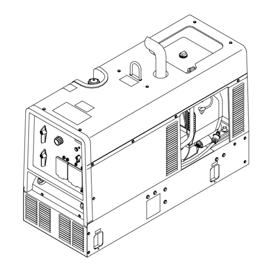
Page 66: Parts List And Diagram
SECTION 14 – PARTS LIST Hardware is common and not available unless listed. Figure 14-1. Main Assembly (Onan Engine) ST-801 742-D OM-405 Page 62... - Page 67 Item Dia. Part Mkgs. Description Quantity Figure 14-1. Main Assembly ....181 881 GROMMET, neck filler ..........
- Page 68 Item Dia. Part Mkgs. Description Quantity Figure 14-1. Main Assembly (Continued) ....Fig 14-3 GENERATOR ........... .
- Page 69 Item Dia. Part Mkgs. Description Quantity Figure 14-2. Panel, Front w/Components (Fig 14-1 Item 43) (Continued) ....184 754 SWITCH, polarity ..........
- Page 70 Item Part Description Quantity Figure 14-3. Generator (Fig 14-1 Item 23) ..+194 621 Housing, Generator Front (consisting of) ........
- Page 71 Effective January 1, 2000 (Equipment with a serial number preface of “LA” or newer) This limited warranty supersedes all previous Miller warranties and is exclusive with no other Warranty Questions? guarantees or warranties expressed or implied. Call LIMITED WARRANTY – Subject to the terms and conditions Induction Heating Coils and Blankets below, Miller Electric Mfg.
-
Page 72: Options And Accessories
Always provide Model Name and Serial/Style Number. Contact your Distributor for: Welding Supplies and Consumables Options and Accessories To locate a distributor or service agency near you, call 1-800-4-A-Miller or visit our Personal Safety Equipment website at www.MillerWelds.com Service and Repair Miller Electric Mfg. Co.
Need help?
Do you have a question about the Bobcat 225 NT and is the answer not in the manual?
Questions and answers