Table of Contents
Advertisement
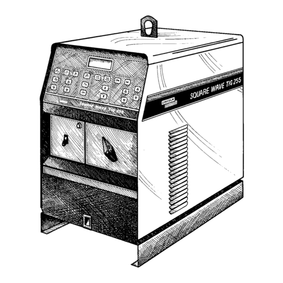
SQUARE WAVE TIG 255
Safety Depends on You
Lincoln arc welding and cutting
equipment is designed and built
with safety in mind. However, your
overall safety can be increased by
proper installation ... and thought-
ful operation on your part. DO
NOT INSTALL, OPERATE OR
REPAIR THIS EQUIPMENT
WITHOUT
READING
MANUAL AND THE SAFETY
PRECAUTIONS CONTAINED
THROUGHOUT. And, most
importantly, think before you act
and be careful.
World's Leader in Welding and Cutting Products
Sales and Service through Subsidiaries and Distributors Worldwide
22801 St. Clair Ave. Cleveland, Ohio 44117-1199 U.S.A. Tel. (216) 481-8100
RETURN TO MAIN INDEX
For use with machine Code Numbers
For use with machine Code Numbers
For use with machine Code Numbers
For use with machine Code Numbers
For use with machine Code Numbers
For use with machine Code Numbers
THIS
SERVICE MANUAL
10022
10023
10024
10025
10026
10134
Premier Manufacturer of Industrial Motors
SVM100-A
December 1995
Advertisement
Chapters
Table of Contents
Troubleshooting

Related Manuals for Lincoln Electric SQUARE WAVE TIG 255 SVM100-A


Summary of Contents for Lincoln Electric SQUARE WAVE TIG 255 SVM100-A
-
Page 1: Square Wave Tig
SQUARE WAVE TIG 255 For use with machine Code Numbers For use with machine Code Numbers For use with machine Code Numbers For use with machine Code Numbers For use with machine Code Numbers For use with machine Code Numbers Safety Depends on You Lincoln arc welding and cutting equipment is designed and built... -
Page 2: Fumes And Gases
Miami, Florida 33135 or CSA Standard W117.2-1974. A Free copy of “Arc Welding Safety” booklet E205 is available from the Lincoln Electric Company, 22801 St. Clair Avenue, Cleveland, Ohio 44117-1199. BE SURE THAT ALL INSTALLATION, OPERATION, MAINTENANCE AND REPAIR PROCEDURES ARE PER- FORMED ONLY BY QUALIFIED INDIVIDUALS. - Page 3 WELDING SPARKS can cause fire or explosion. 4.a. Remove fire hazards from the welding area. If this is not possible, cover them to prevent the welding sparks from starting a fire. Remember that welding sparks and hot materials from welding can easily go through small cracks and openings to adjacent areas.
-
Page 4: Safety
FOR ENGINE powered equipment. 7.a. Turn the engine off before troubleshooting and maintenance work unless the maintenance work requires it to be running. ____________________________________________________ 7.b. Operate engines in open, well-ventilated areas or vent the engine exhaust fumes outdoors. ____________________________________________________ 7.c. Do not add the fuel near an open flame welding arc or when the engine is running. - Page 5 PRÉCAUTIONS DE SÛRETÉ Pour votre propre protection lire et observer toutes les instruc- tions et les précautions de sûreté specifiques qui parraissent dans ce manuel aussi bien que les précautions de sûreté générales suivantes: Sûreté Pour Soudage A L’Arc 1. Protegez-vous contre la secousse électrique: a.
-
Page 6: Table Of Contents
MASTER TABLE OF CONTENTS FOR ALL SECTIONS Page Safety ...i-iv Installation ...Section A Technical Specifications ...A-1 Location ...A-2 High Frequency Interference Protection ...A-2 Input Connections...A-3 Output Connections ...A-4 Operation ...Section B Safety Precautions...B-1 Graphic Symbols...B-2 – B-3 General Description ...B-4 Design Features and Advantages ...B-4 Welding Capability ...B-5 Limitations...B-5... -
Page 7: Installation Section
TABLE OF CONTENTS - INSTALLATION SECTION - Installation ...Section A Technical Specifications ...A-1 Input and Output Specifications Cable and Fuse Sizes Physical Dimensions Location ...A-2 Stacking ...A-2 Tilting...A-2 High Frequency Interference Protection ...A-2 Input Connections...A-3 Reconnect Procedure ...A-4 Output Connections ...A-4 Section A SQUARE WAVE TIG 255... -
Page 8: Installation
TECHNICAL SPECIFICATIONS – SQUARE WAVE TIG 255 Standard Voltage 208/230/460/1/60 230/460/575/1/60 200/240/400/1/50/60 220/380/440/1/50/60 380/415/500/1/50/60 220/380/415/1/50/60 Duty Cycle 40% Duty Cycle NEMA Class II (40) 60% Duty Cycle 100% Duty Cycle Welding Current Range (Continuous) 5-315 Amps AC and DC RECOMMENDED INPUT WIRE AND FUSE SIZES For all Stick, DC TIG, and Balanced AC TIG Welding at 255A/30V/40% Duty Cycle Based on the 1993 US. -
Page 9: Location
Read entire installation section before starting installation. SAFETY PRECAUTIONS WARNING ELECTRIC SHOCK can kill. • Only qualified personnel should perform this installation. • Turn the input power OFF at the disconnect switch or fuse box before working on this equipment. •... -
Page 10: Installation
4. Keep the torch in good repair and all connections tight to reduce high frequency leakage. 5. The work terminal must be connected to a ground within ten feet of the welder, using one of the following methods: a) A metal underground water pipe in direct contact with the earth for ten feet or more. -
Page 11: Reconnect Procedure
RECONNECT PROCEDURE On multiple input voltage welders, be sure the recon- nect panel is connected per the following instructions for the voltage being supplied to the welder. CAUTION Failure to follow these instructions can cause immedi- ate failure of components within the welder. ___________________________________________ Welders are shipped connected for the highest input voltage as listed on the rating Plate. -
Page 12: Stick Electrode Cable Connection
TABLE A.1 Cable Sizes for Combined Lengths of Copper Electrode and Work Cable Lengths up to Machine Size 100 ft 100 to 200 ft 255 Amp #2 (35mm 2 ) #1 (45mm 2 ) 40% Duty Cycle Connect the TIG torch gas and water fittings to the welder fittings. -
Page 13: General Description
TABLE OF CONTENTS - OPERATION SECTION - Operation ...Section B Safety Precautions ...B-1 Graphic Symbols ...B-2 - B-3 General Description ...B-4 Design Features and Advantages...B-4 Welding Capability ...B-5 Limitations ...B-5 Controls and Settings...B-6 Control Panel Keys ...B-6 Case Front Controls ...B-7 Hand and Foot Amptrol Operation ...B-8 Welding Operation...B-8 - B-11 TIG Welding Guidelines ...B-8... -
Page 14: Operation
OPERATING INSTRUCTIONS Read and understand entire section before operating machine. GENERAL WARNINGS SAFETY PRECAUTIONS Observe additional Safety Guidelines detailed in the beginning of this manual. SQUARE WAVE TIG 255 OPERATION WARNING ELECTRIC SHOCK can kill. • Do not touch electrically live parts or electrode with skin or wet clothing. -
Page 15: Operation
GRAPHIC SYMBOLS THAT APPEAR ON THIS MACHINE OR IN THIS MANUAL TIG 2-STEP & TIG 4-STEP STICK CURRENT CONTROL OUTPUT LOCAL CUR- RENT CON- TROL REMOTE CUR- RENT CON- TROL INCREASE OUTPUT DECREASE HIGH FRE- QUENCY OPERATION & & AFTERFLOW / AFTERFLOW TIME CONTINUOUS... - Page 16 GRAPHIC SYMBOLS THAT APPEAR ON THIS MACHINE OR IN THIS MANUAL (CONT.) AC WAVE BAL- ANCE PULSED PER SECOND OVER TEMPER- ATURE INPUT POWER & POLARITY & POLARITY DO NOT SWITCH WHILE WELD- WARNING WATER (COOLANT) OUTPUT WATER (COOLANT) INPUT SQUARE WAVE TIG 255 OPERATION GAS OUTPUT...
-
Page 17: General Description
GENERAL DESCRIPTION The Square Wave TIG 255 is a constant current, single range square wave AC/DC TIG (GTAW) arc welding power source with built-in high frequency stabilization. It also has stick (SMAW) capability. It is available from the factory in one model only; there are no factory installed options, only variations in input voltage and frequency. -
Page 18: Welding Capability
• Strain relief holes in base for welding cables, gas and water hoses and control cables. • Easy access for input connections. Connections are simple strip and clamp of input wires (no lugs required). • Low fan noise at idle. •... -
Page 19: Controls And Settings
CONTROLS AND SETTINGS All operator controls and adjustments are located on the case front of the Square Wave TIG 255. Refer to Figures B.1, B.2.a and B.2.b and corresponding explanations. THE LINCOLN ELECTRIC COMPANY CLEVELAND, OHIO USA WELD MODE TIG 2-STEP... -
Page 20: Case Front Controls
7. CONTROL PANEL: The display is divided into five sections. See Figures B.2.a and B.2.b. FIGURE B.2.a - DISPLAY A. AC/DC INDICATOR D. MOMENTARY DISPLAY B. VOLTMETER E. BAR GRAPH C. AMMETER FIGURE B.2.b - DISPLAY A. AC/DC INDICATOR: This symbol represents the output polarity of the 255 . -
Page 21: Hand And Foot Amptrol Operation
HAND AND FOOT AMPTROL ACCESSORY OPERATION Both the Hand and Foot Amptrol work in a similar manner. They are meant to be used for remote current control when Remote Current Control is selected. The TIG 2-Step mode must be selected when using an Amptrol for remote current control. -
Page 22: Tig Welding Sequence Of Operation (2-Step Mode
TYPICAL CURRENT RANGES DCEP ( + ) DCEN ( - ) Tungsten 1%, 2% 1%, 2% Electrode Thoriated Thoriated Diameter Tungsten Tungsten in. (mm) .010 (.25) 2-15 0.020 (.50) 5-20 0.040 (1.0) 15-80 1/16 (1.6) 70-150 10-20 3/32 (2.4) 150-250 15-30 (3.2) 250-400... -
Page 23: Hand And Foot Amptrol Operation
9. Set the Afterflow time with the Seconds Up/Down keys. Afterflow time provides shielding gas flow (and cooling water, if used) after the weld. Use short Afterflow times with low currents and small tungstens, use long afterflow times at high output currents with large tungstens. -
Page 24: Advanced Tig Welding Features
B-11 ADVANCED TIG WELDING FEATURES AC WAVE BALANCE AND AUTO BALANCE™ AC Wave Balance is a feature unique to square wave TIG power sources. It is active only in AC TIG mode. It controls the amount of positive and negative current in the AC output. -
Page 25: Overload Protection
B-12 OPERATION CAUTION Note that some types of equipment, especially pumps and motors, have starting currents which are signifi- cantly higher than their running currents. These higher starting currents may cause the circuit breaker to open. If this situation occurs, the user should refrain from using the Square Wave TIG 255 auxiliary for that equipment. - Page 26 B-13 NOTES SQUARE WAVE TIG 255...
-
Page 27: Accessories Section
Section C TABLE OF CONTENTS - ACCESSORIES SECTION - Accessories...Section C Available Option and Accessories ...C-1 Undercarriage Function ...C-1 Installation of Field Installed Options ...C-1 SQUARE WAVE TIG 255... -
Page 28: Accessories
OPTIONS / ACCESSORIES • Hand Amptrol (K812) • Foot Amptrol (K870) • Arc Start Switch (K814) • Magnum Cooler Horizontal TIG Mounting Bracket (K559-2) • Undercarriage (K932-1) UNDERCARRIAGE FUNCTION The Square Wave TIG 255 is designed to be used with a Lincoln K932-1 Undercarriage. Complete installation instructions are included with the K932-1 undercarriage. -
Page 29: Routine And Periodic Maintenance
Section D TABLE OF CONTENTS - MAINTENANCE SECTION - Maintenance ...Section D Safety Precautions...D-1 Routine and Periodic Maintenance ...D-1 General Assembly Exploded View...D-2 SQUARE WAVE TIG 255... -
Page 30: Maintenance
MAINTENANCE SAFETY PRECAUTIONS ROUTINE AND PERIODIC MAINTENANCE To avoid receiving a high frequency shock, keep the TIG torch and cables in good condition. 1. Disconnect power supply lines to machine before performing periodic maintenance. 2. Periodically clean the inside of the machine with a low pressure air system. - Page 31 FIGURE D.1 - GENERAL ASSEMBLY EXPLODED VIEW 1, MAIN TRANSFORMER 2. OUTPUT TERMINALS 3. POLARITY SWITCH 4. RECTIFIER ASSEMBLY MAINTENANCE 5. CONTROL BOX ASSEMBLY 6. SPARK GAP ASSEMBLY 7. PROTECTION PC BOARD - (Mounted to rear of control box assembly) SQUARE WAVE TIG 255...
- Page 32 NOTES SQUARE WAVE TIG 255...
-
Page 33: Thermal Protection
- THEORY OF OPERATION SECTION - Theory of Operation Section...Section E Power Supply Operation ...E-1 - E-5 Input Line Voltage and Main Transformer...E-1 Output Rectification and Feedback Control ...E-2 High Voltage / High Frequency Circuit ...E-3 DC Welding Output ...E-4 AC Welding Output ...E-5 SCR Operation...E-6 Thermal Protection ...E-7... -
Page 34: Input Line Voltage And Main Transformer
THEORY OF OPERATION INPUT LINE VOLTAGE AND MAIN TRANSFORMER LINE MAIN SWITCH TRANSFORMER POWER FACTOR CAPACITORS PROTECTION 115VAC SNUBBER BOARD 115 VAC RECEPTACLE REMOTE RECEPTACLE The desired single-phase input power is connected to the TIG 255 through a line switch located on the front panel. -
Page 35: Theory Of Operation
THEORY OF OPERATION OUTPUT RECTIFICATION AND FEEDBACK CONTROL LINE MAIN SWITCH TRANSFORMER POWER FACTOR CAPACITORS PROTECTION 115VAC SNUBBER BOARD 115 VAC RECEPTACLE REMOTE RECEPTACLE The AC output from the main transformer secondary is rectified and controlled through the SCR bridge. Output current is sensed at the shunt, as a low volt- age signal, and fed back to the control board. -
Page 36: High Voltage / High Frequency Circuit
THEORY OF OPERATION HIGH VOLTAGE / HIGH FREQUENCY CIRCUIT LINE MAIN SWITCH TRANSFORMER POWER FACTOR CAPACITORS PROTECTION 115VAC SNUBBER BOARD 115 VAC RECEPTACLE REMOTE RECEPTACLE The control board passes the 115vac through the pro- tection / snubber board to the primary of the high volt- age transformer. -
Page 37: Dc Welding Output
THEORY OF OPERATION LINE MAIN SWITCH TRANSFORMER POWER FACTOR CAPACITORS PROTECTION 115VAC SNUBBER BOARD 115 VAC RECEPTACLE REMOTE RECEPTACLE When the polarity switch is placed in either DC posi- tion, the AC voltage from the main transformer sec- ondary is applied to the SCR bridge. The SCR bridge and choke circuits are connected in a conventional full wave bridge and filter configuration, resulting in a con- PRIMARY... -
Page 38: Ac Welding Output
THEORY OF OPERATION LINE MAIN SWITCH TRANSFORMER POWER FACTOR CAPACITORS PROTECTION 115VAC SNUBBER BOARD 115 VAC RECEPTACLE REMOTE RECEPTACLE By rotating the polarity switch to the AC position the welding power circuit is changed. One lead (X2) of the main transformer secondary is connected to the machine’s output work stud. -
Page 39: Scr Operation
THEORY OF OPERATION A silicon controlled rectifier (SCR) is a three terminal device used to control rather large currents to a load. An SCR acts very much like a switch. When a gate signal is applied to the SCR it is turned ON and there is current flow from anode to cathode. -
Page 40: Thermal Protection
THEORY OF OPERATION A thermostat protects the machine from excessive operating temperatures. Excessive operating temper- atures may be caused by a lack of cooling air or oper- ating the machine beyond the duty cycle and output rating. If excessive operating temperature should occur, the thermostat will prevent output voltage or current and the yellow indicator light will glow. -
Page 41: Square Wave Tig
TABLE OF CONTENTS - TROUBLESHOOTING & REPAIR SECTION - Troubleshooting & Repair Section ...Section F Safety Precautions...F-1 How to Use Troubleshooting Guide ...F-1 PC Board Troubleshooting Procedures ...F-2 Troubleshooting Guide ...F-3 - F-15 PC Board Connector Locations ...F-16 Test Procedures Control Transformer Voltage Test ...F-17 Protection/Snubber Board Continuity Test ...F-20 Arc Start Trigger Circuit Test ...F-23... -
Page 42: Troubleshooting And Repair
TROUBLESHOOTING & REPAIR HOW TO USE TROUBLESHOOTING GUIDE Service and Repair should only be performed by Lincoln Electric Factory Trained Personnel. Unauthorized repairs performed on this equipment may result in danger to the technician and machine operator and will invalidate your factory warranty. For your safety and to avoid Electrical Shock, please observe all safety notes and precautions detailed throughout this manual. -
Page 43: Pc Board Troubleshooting Procedures
TROUBLESHOOTING & REPAIR PC BOARD TROUBLESHOOTING PROCEDURES WARNING CAUTION: Sometimes machine failures appear to be due to PC board failures. These problems can sometimes be traced to poor electrical connections. To avoid problems when troubleshooting and replac- ing PC boards, please use the following procedure: 1. -
Page 44: Troubleshooting Guide
Stick or TIG modes. If for any reason you do not understand the test procedures or are unable to perform the tests/repairs safely, contact the Lincoln Electric Service Department for technical troubleshooting assistance before you proceed call 216-383-2531 or 1-800-833-9353. - Page 45 Machine may have OCV in the Stick Mode. If for any reason you do not understand the test procedures or are unable to perform the tests/repairs safely, contact the Lincoln Electric Service Department for technical troubleshooting assistance before you proceed call 216-383-2531 or 1-800-833-9353.
- Page 46 (The machine is not externally loaded). If for any reason you do not understand the test procedures or are unable to perform the tests/repairs safely, contact the Lincoln Electric Service Department for technical troubleshooting assistance before you proceed call 216-383-2531 or 1-800-833-9353.
- Page 47 Machine may have low or no out- put. If for any reason you do not understand the test procedures or are unable to perform the tests/repairs safely, contact the Lincoln Electric Service Department for technical troubleshooting assistance before you proceed call 216-383-2531 or 1-800-833-9353.
- Page 48 - machine operat- ing normally. If for any reason you do not understand the test procedures or are unable to perform the tests/repairs safely, contact the Lincoln Electric Service Department for technical troubleshooting assistance before you proceed call 216-383-2531 or 1-800-833-9353.
- Page 49 The machine operates normally. If for any reason you do not understand the test procedures or are unable to perform the tests/repairs safely, contact the Lincoln Electric Service Department for technical troubleshooting assistance before you proceed call 216-383-2531 or 1-800-833-9353.
- Page 50 The machine has output. If for any reason you do not understand the test procedures or are unable to perform the tests/repairs safely, contact the Lincoln Electric Service Department for technical troubleshooting assistance before you proceed call 216-383-2531 or 1-800-833-9353.
- Page 51 Arc “Flutters” when TIG welding. If for any reason you do not understand the test procedures or are unable to perform the tests/repairs safely, contact the Lincoln Electric Service Department for technical troubleshooting assistance before you proceed call 216-383-2531 or 1-800-833-9353.
- Page 52 If for any reason you do not understand the test procedures or are unable to perform the tests/repairs safely, contact the Lincoln Electric Service Department for technical troubleshooting assistance before you proceed call 216-383-2531 or 1-800-833-9353.
- Page 53 If for any reason you do not understand the test procedures or are unable to perform the tests/repairs safely, contact the Lincoln Electric Service Department for technical troubleshooting assistance before you proceed call 216-383-2531 or 1-800-833-9353.
- Page 54 TIG Mode and has normal output. If for any reason you do not understand the test procedures or are unable to perform the tests/repairs safely, contact the Lincoln Electric Service Department for technical troubleshooting assistance before you proceed call 216-383-2531 or 1-800-833-9353.
- Page 55 NOT operating. If for any reason you do not understand the test procedures or are unable to perform the tests/repairs safely, contact the Lincoln Electric Service Department for technical troubleshooting assistance before you proceed call 216-383-2531 or 1-800-833-9353.
- Page 56 Stick Mode. If for any reason you do not understand the test procedures or are unable to perform the tests/repairs safely, contact the Lincoln Electric Service Department for technical troubleshooting assistance before you proceed call 216-383-2531 or 1-800-833-9353.
-
Page 57: Pc Board Connector Locations
TROUBLESHOOTING & REPAIR PC BOARD CONNECTOR LOCATIONS G2150 SQUARE WAVE 255 CONTROL FIGURE F.1 - CONTROL BOARD CONNECTORS 1J11 1J10 12J10 FIGURE F.2 - PROTECTION/SNUBBER BOARD CONNECTORS 13J6 1J13 1J12 PROTECTION/SNUBBER 10J11 14J12 16J13 F-16 12J6 1J14 1J15 L9255 8J14 6J15 SQUARE WAVE TIG 255... -
Page 58: Control Transformer Voltage Test
TROUBLESHOOTING & REPAIR CONTROL TRANSFORMER (T2) VOLTAGE TEST Service and repair should only be performed by Lincoln Electric factory trained person- nel. Unauthorized repairs performed on this equipment may result in danger to the technician or machine operator and will invalidate your factory warranty. For your safe- ty and to avoid electrical shock please observe all safety notes and precautions detailed throughout this manual. -
Page 59: Control Box
TROUBLESHOOTING & REPAIR CONTROL TRANSFORMER (T2) VOLTAGE TEST (continued) CONTROL BOX CONTROL BOARD LOCATED INSIDE CONTROL TRANSFORMER LOCATED INSIDE FIGURE F.3 - LOCATION OF CONTROL BOARD AND CONTROL TRANSFORMER. TEST PROCEDURE 1. Remove main supply power to machine 2. Locate and remove Plug J8 from control board, located in the control box. - Page 60 F-19 TROUBLESHOOTING & REPAIR CONTROL TRANSFORMER (T2) VOLTAGE TEST (continued) G2150 SQUARE WAVE 255 CONTROL FIGURE F.4 - CONTROL BOARD AND TRANSFORMER. 7. Test the resistance from 8J14, on the protection/ snubber board, to the #432 lead at the control transformer. Also check resistance from 4J14, on the pro- tection/snubber board, to the #433 lead at the control transformer.
-
Page 61: Protection/Snubber Board Continuity Test
TROUBLESHOOTING & REPAIR PROTECTION/SNUBBER BOARD CONTINUITY TEST Service and repair should only be performed by Lincoln Electric factory trained person- nel. Unauthorized repairs performed on this equipment may result in danger to the technician or machine operator and will invalidate your factory warranty. For your safe- ty and to avoid electrical shock please observe all safety notes and precautions detailed throughout this manual. - Page 62 F-21 TROUBLESHOOTING & REPAIR PROTECTION/SNUBBER BOARD CONTINUITY TEST (continued) CONTROL BOX PROTECTION/SNUBBER BOARD LOCATED ON BACK OF CONTROL BOX FIGURE F.5 - PROTECTION/SNUBBER BOARD LOCATION TEST PROCEDURE 1. Remove main supply power to machine. 2. Locate and remove all harness plugs from the protection/snubber board locat- ed on the back of the control box.
- Page 63 TROUBLESHOOTING & REPAIR PROTECTION/SNUBBER BOARD CONTINUITY TEST (continued) 1J11 1J12 1J10 12J10 10J11 FIGURE F.6 - PROTECTION/SNUBBER BOARD TEST POINTS. Check Points Component(s) Being Checked 5J13 to 5J12 L1 and Board Trace 13J13 to 12J12 L2 and Board Trace 4J13 to 4J12 L3 and Board Trace 12J13 to 11J12 L4 and Board Trace...
-
Page 64: Arc Start Trigger Circuit Test
TROUBLESHOOTING & REPAIR ARC START TRIGGER CIRCUIT TEST Service and repair should only be performed by Lincoln Electric factory trained person- nel. Unauthorized repairs performed on this equipment may result in danger to the technician or machine operator and will invalidate your factory warranty. For your safe- ty and to avoid electrical shock please observe all safety notes and precautions detailed throughout this manual. - Page 65 TROUBLESHOOTING & REPAIR ARC START TRIGGER CIRCUIT TEST (continued) CONTROL BOX CONTROL BOARD LOCATED INSIDE PROTECTION/SNUBBER BOARD LOCATED ON BACK OF CONTROL BOX FIGURE F.7 - LOCATION OF PROTECTION/SNUBBER BOARD. TEST PROCEDURE 1. Remove main supply power to machine 2. Remove plug J6 from the control board 3.
- Page 66 F-25 TROUBLESHOOTING & REPAIR ARC START TRIGGER CIRCUIT TEST (continued) 3J12 10J12 FIGURE F.9 - PROTECTION/SNUBBER BOARD TEST POINTS. 6. Test the resistance from 11J13 on the projection/ snubber board to pin “D” on the six pin amphenol receptacle. (Lead #311).
-
Page 67: Static Scr Test
TROUBLESHOOTING & REPAIR STATIC SCR TEST Service and repair should only be performed by Lincoln Electric factory trained person- nel. Unauthorized repairs performed on this equipment may result in danger to the technician or machine operator and will invalidate your factory warranty. For your safe- ty and to avoid electrical shock please observe all safety notes and precautions detailed throughout this manual. - Page 68 F-27 TROUBLESHOOTING & REPAIR STATIC SCR TEST (continued) REMOVE PLUGS J10 & J13 FIGURE F.11 - PROTECTION BOARD PLUG LOCATIONS TEST PROCEDURE 1. Remove main supply power to machine 2. Remove plug J10 and J13 from the pro- tection/snubber board. Refer to Figure F.11.
-
Page 69: Active Scr Test
TROUBLESHOOTING & REPAIR ACTIVE SCR TEST Service and repair should only be performed by Lincoln Electric factory trained person- nel. Unauthorized repairs performed on this equipment may result in danger to the technician or machine operator and will invalidate your factory warranty. For your safe- ty and to avoid electrical shock please observe all safety notes and precautions detailed throughout this manual. - Page 70 F-29 TROUBLESHOOTING & REPAIR ACTIVE SCR TEST (continued) REMOVE PLUGS J10 & J13 FIGURE F.13 - PROTECTION/SNUBBER BOARD PLUG LOCATIONS. TEST PROCEDURE 1. Remove main supply power to machine 2. Remove plugs J10 and J13 from protec- tion/snubber board. See Figure F.13. 3.
-
Page 71: Battery Test
TROUBLESHOOTING & REPAIR ACTIVE SCR TEST (continued) 6volt Lantern Battery To test SCRs construct the circuit outlined above. Resistor values are plus or minus ten percent. The voltmeter scale should be low, approximately 0-5 or 0-10 volts DC. FIGURE F.15 - SILICON CONTROLLED RECTIFIER TEST SETUP. SILICON CONTROLLED RECTIFIER TEST (Heat Sink Mounted Units) -
Page 72: Normal Open Circuit Voltage Waveform Dc Stick Mode
F-31 TROUBLESHOOTING & REPAIR NORMAL OPEN CIRCUIT VOLTAGE WAVEFORM HIGH VOLTAGE / HIGH FREQUENCY can damage test equipment. • Perform all voltage and waveform checks with high frequency circuit OFF. _____________________________________________________________________ This is the typical DC (+) output voltage waveform generated from a properly operat- ing machine. -
Page 73: Normal Open Circuit Voltage Waveform Ac Stick Mode
TROUBLESHOOTING & REPAIR NORMAL OPEN CIRCUIT VOLTAGE WAVEFORM AC STICK MODE HIGH VOLTAGE / HIGH FREQUENCY can damage test equipment. • Perform all voltage and waveform checks with high frequency circuit OFF. _____________________________________________________________________ 50 volts This is the typical AC output voltage wave- form generated from a properly operating machine. -
Page 74: Normal Open Circuit Voltage Waveform Dc Tig Mode
F-33 TROUBLESHOOTING & REPAIR NORMAL OPEN CIRCUIT VOLTAGE WAVEFORM HIGH VOLTAGE / HIGH FREQUENCY can damage test equipment. • Perform all voltage and waveform checks with high frequency circuit OFF. _____________________________________________________________________ This is the typical DC (+) output voltage waveform generated from a properly operat- ing machine. -
Page 75: Normal Open Circuit Voltage Waveform Ac Tig Mode
TROUBLESHOOTING & REPAIR NORMAL OPEN CIRCUIT VOLTAGE WAVEFORM HIGH VOLTAGE / HIGH FREQUENCY can damage test equipment. • Perform all voltage and waveform checks with high frequency circuit OFF. _____________________________________________________________________ 50 volts This is the typical AC output voltage wave- form generated from a properly operating machine. -
Page 76: Typical Output Voltage Waveform Machine Loaded Dc Tig Mode
F-35 TROUBLESHOOTING & REPAIR TYPICAL OUTPUT VOLTAGE WAVEFORM - MACHINE LOADED HIGH VOLTAGE / HIGH FREQUENCY can damage test equipment. • Perform all voltage and waveform checks with high frequency circuit OFF. _____________________________________________________________________ MACHINE LOADED TO 200 AMPS AT 50 VDC This is a typical DC (+) output voltage wave- form generated from a properly operating machine. - Page 77 TROUBLESHOOTING & REPAIR AC TIG MODE (AUTO - BALANCE ON) HIGH VOLTAGE / HIGH FREQUENCY can damage test equipment. • Perform all voltage and waveform checks with high frequency circuit OFF. _____________________________________________________________________ 20 volts MACHINE LOADED TO 50 AMPS AT 26VAC These are typical AC output voltage wave- forms generated from a properly operating machine.
-
Page 78: Typical Scr Gate Voltage Waveform
F-37 TROUBLESHOOTING & REPAIR TYPICAL SCR GATE VOLTAGE WAVEFORM HIGH VOLTAGE / HIGH FREQUENCY can damage test equipment. • Perform all voltage and waveform checks with high frequency circuit OFF. _____________________________________________________________________ This is the typical SCR gate pulse voltage waveform. The machine was in an open circuit condition (no load) and operating properly. - Page 79 TROUBLESHOOTING & REPAIR ABNORMAL OPEN CIRCUIT VOLTAGE - DC STICK MODE ONE OUTPUT SCR NOT FUNCTIONING HIGH VOLTAGE / HIGH FREQUENCY can damage test equipment. • Perform all voltage and waveform checks with high frequency circuit OFF. _____________________________________________________________________ 50 volts This is NOT the typical DC (+) output volt- age waveform.
- Page 80 F-39 TROUBLESHOOTING & REPAIR ABNORMAL OPEN CIRCUIT VOLTAGE - AC STICK MODE ONE OUTPUT SCR NOT FUNCTIONING HIGH VOLTAGE / HIGH FREQUENCY can damage test equipment. • Perform all voltage and waveform checks with high frequency circuit OFF. _____________________________________________________________________ This is NOT the typical AC output voltage waveform.
-
Page 81: Fan Motor And Blade Removal
TROUBLESHOOTING & REPAIR FAN MOTOR AND BLADE REMOVAL Service and repair should only be performed by Lincoln Electric factory trained person- nel. Unauthorized repairs performed on this equipment may result in danger to the technician or machine operator and will invalidate your factory warranty. For your safe- ty and to avoid electrical shock please observe all safety notes and precautions detailed throughout this manual. - Page 82 F-41 TROUBLESHOOTING & REPAIR FAN MOTOR AND BLADE REMOVAL (continued) Fan Baffle TEST PROCEDURE 1. Remove main supply power to machine. 2. Remove case sides and top. 3. Locate and SUPPORT rectifier and fan baffle assembly. 4. Remove the two self-tapping screws from the input access door.
-
Page 83: Scr Heatsink Assembly Removal
TROUBLESHOOTING & REPAIR SCR HEAT SINK ASSEMBLY REMOVAL Service and repair should only be performed by Lincoln Electric factory trained person- nel. Unauthorized repairs performed on this equipment may result in danger to the technician or machine operator and will invalidate your factory warranty. For your safe- ty and to avoid electrical shock please observe all safety notes and precautions detailed throughout this manual. - Page 84 F-43 TROUBLESHOOTING & REPAIR SCR HEAT SINK ASSEMBLY REMOVAL (continued) SCR Heat Sink Assemblies TEST PROCEDURE 1. Remove main power supply to machine. 2. Remove case sides and top. 3. Locate SCR heat sink assemblies. 4. Remove all gate, snubber and cable leads from the SCR heat sink assembly that is to be serviced.
-
Page 85: Retest After Repair
TROUBLESHOOTING & REPAIR RETEST AFTER REPAIR Should a machine under test be rejected for any reason requiring the removal of any mechanical part that could affect the machine’s electrical characteristics, or if any electrical components are repaired or replaced, the machine must be retested. Input Volts/Hertz Voltage Across Stick Mode OCV... - Page 86 F-45 TROUBLESHOOTING & REPAIR RETEST AFTER REPAIR (cont’d) MAIN TRANSFORMER SECONDARY VOLTAGES (See Figure F.16) X3 – X4 (230 – 232) X3 – X5 (230 – 52A) SQUARE WAVE TIG 255 FIGURE F.16 - TRANSFORMER LEAD TEST POINTS. Test Points X1 –...
- Page 87 Section G TABLE OF CONTENTS - ELECTRICAL DIAGRAMS - Electrical Diagrams ...Section G Control PC Board (G2150) Components ...G-2 Protection Snubber PC Board (L9255) Components...G-6 Wiring Diagram ...G-9 Machine Schematic ...G-10 Control Board Schematic (G2150)...G-11 Control Board Schematic(cont’d)...G-12 Protection/Snubber Board Schematic (l9255) ...G-13 Keypad LED Board (L9212)...G-14 SQUARE WAVE TIG 255...
-
Page 88: Electrical Diagrams
ELECTRICAL DIAGRAMS CONTROL BOARD (G2150) NOTE: Lincoln Electric assumes no responsibility for liabilities resulting from board level troubleshooting. PC Board repairs will invalidate your factory warranty. Individual Printed Circuit Board Components are not avail- able from Lincoln Electric. This information is provided for reference only. Lincoln Electric discourages board level troubleshooting and repair since it may compromise the quality of the design and may result in danger to the Machine Operator or Technician. - Page 89 RFD110 DIODE-AXLDS,1A,30V,SCHOTTKY NOTE: Lincoln Electric assumes no responsibility for liabilities resulting from board level troubleshooting. PC Board repairs will invalidate your factory warranty. Individual Printed Circuit Board Components are not avail- able from Lincoln Electric. This information is provided for reference only. Lincoln Electric discourages board level troubleshooting and repair since it may compromise the quality of the design and may result in danger to the Machine Operator or Technician.
- Page 90 RESISTOR-MF,1/4W,26.7K,1% R233,R234 NOTE: Lincoln Electric assumes no responsibility for liabilities resulting from board level troubleshooting. PC Board repairs will invalidate your factory warranty. Individual Printed Circuit Board Components are not avail- able from Lincoln Electric. This information is provided for reference only. Lincoln Electric discourages board level troubleshooting and repair since it may compromise the quality of the design and may result in danger to the Machine Operator or Technician.
- Page 91 NOTES SQUARE WAVE TIG 255...
- Page 92 PROTECTION/SNUBBER BOARD (L9255) NOTE: Lincoln Electric assumes no responsibility for liabilities resulting from board level troubleshooting. PC Board repairs will invalidate your factory warranty. Individual Printed Circuit Board Components are not avail- able from Lincoln Electric. This information is provided for reference only. Lincoln Electric discourages board level troubleshooting and repair since it may compromise the quality of the design and may result in danger to the Machine Operator or Technician.
- Page 93 R5,R6 RESISTOR-MF,1/4W,26.7,1% NOTE: Lincoln Electric assumes no responsibility for liabilities resulting from board level troubleshooting. PC Board repairs will invalidate your factory warranty. Individual Printed Circuit Board Components are not avail- able from Lincoln Electric. This information is provided for reference only. Lincoln Electric discourages board level troubleshooting and repair since it may compromise the quality of the design and may result in danger to the Machine Operator or Technician.
- Page 94 NOTES SQUARE WAVE TIG 255...
-
Page 95: Wiring Diagram
ELECTRICAL DIAGRAMS WIRING DIAGRAM - SQUARE WAVE TIG 255 T O G R O U N D P E R N A T I O N A L E L E C T R I C C O D E NOTE: This diagram is for reference only. -
Page 96: Machine Schematic
ELECTRICAL DIAGRAMS MACHINE SCHEMATIC — SQUARE WAVE TIG 255 S C R 4 C A T H O D E 9 J 5 S C R 4 G A T E 4 J 5 S C R 1 G A T E 1 J 5 S C R 2 G A T E 2 J 5... -
Page 97: Control Board Schematic (G2150
PC board version. This diagram is intended to provide general information regarding PC board function. Lincoln Electric discourages board level troubleshooting and repair since it may compromise the quality of the design and may result in Danger to the Machine Operator or Technician. Improper PC board repairs could result in damage to the machine. - Page 98 PC board version. This diagram is intended to provide general information regarding PC board function. Lincoln Electric discourages board level troubleshooting and repair since it may compromise the quality of the design and may result in Danger to the Machine Operator or Technician. Improper PC board repairs could result in damage to the machine.
-
Page 99: Protection/Snubber Board Schematic (L9255
PC board version. This diagram is intended to provide general information regarding PC board function. Lincoln Electric discourages board level troubleshooting and repair since it may compromise the quality of the design and may result in Danger to the Machine Operator or Technician. Improper PC board repairs could result in damage to the machine. -
Page 100: Keypad Led Board (L9212
PC board version. This diagram is intended to provide general information regarding PC board function. Lincoln Electric discourages board level troubleshooting and repair since it may compromise the quality of the design and may result in Danger to the Machine Operator or Technician. Improper PC board repairs could result in damage to the machine.
Need help?
Do you have a question about the SQUARE WAVE TIG 255 SVM100-A and is the answer not in the manual?
Questions and answers