Lexmark X792 Service Manual
Hide thumbs
Also See for X792:
- Color product study manual (74 pages) ,
- Maintenance manual (16 pages) ,
- Datasheet (8 pages)
Table of Contents
Advertisement
Quick Links
Advertisement
Table of Contents

Related Manuals for Lexmark X792


Summary of Contents for Lexmark X792
- Page 1 Lexmark™ X792 printer Machine Type 7562-4xx • Table of Contents • Start Diagnostics • Safety and Notices • Trademarks • Index Lexmark and Lexmark with diamond design are trademarks of Lexmark International, Inc., registered in the United States and/or other countries.
- Page 2 Lexmark, Lexmark with diamond design, and MarkNet are trademarks of Lexmark International, Inc., registered in the United States and/or other countries. PrintCryption and StapleSmart are trademarks of Lexmark International, Inc.
-
Page 3: Table Of Contents
7562 Table of contents Previous Notices and safety information ......... xvii Laser notice . - Page 4 7562 Characters have jagged or uneven edges ..........2-37 Previous Clipped images .
- Page 5 7562 147.xx—Staging motor error service check ..........2-96 Previous 149.xx—Paper path redrive motor error service check .
- Page 6 7562 D. Collecting information from the user ......... . 2-157 Previous 900.xx System software error .
- Page 7 7562 Auto Detect ..............3-14 Previous PRINT TESTS .
- Page 8 7562 ASIC Test ..............3-28 Previous Feed Test .
- Page 9 7562 Electrophotographic Process (EP Process) ........3-38 Previous Electrophotographic Process basics .
- Page 10 7562 AIO front lower cover removal ............4-3 Previous AIO front upper cover removal .
- Page 11 7562 MPF drive assembly removal ........... . . 4-104 Previous MPF sensor plate assembly removal .
- Page 12 7562 ADF pick pad cover assembly removal ..........4-188 Previous ADF pick roll position cam assembly removal .
- Page 13 7562 550-sheet tray pick assembly removal ..........4-250 Previous 550-sheet tray pick roll assembly removal .
- Page 14 7562 Finisher or stacker LED sensor cover removal .........4-338 Previous Finisher or stacker left access door assembly removal .
- Page 15 7562 HTU sensor (access door interlock) removal ......... . 4-402 Previous HTU sensor (empty bin) removal .
- Page 16 7562 Assembly 10: ADF electronics ........... . . 7-26 Previous Assembly 11: Optional 550-sheet tray .
-
Page 17: Notices And Safety Information
7562 Notices and safety information Previous The following laser notice labels may be affixed to this printer. Next Laser notice Go Back The printer is certified in the U.S. to conform to the requirements of DHHS 21 CFR Subchapter J for Class I (1) laser products, and elsewhere is certified as a Class I laser product conforming to the requirements of IEC 60825-1. - Page 18 7562 stampante, durante il normale funzionamento, le operazioni di servizio o quelle di assistenza tecnica, non Previous ricevano radiazioni laser superiori al livello della classe 1. Avisos sobre el láser Next Se certifica que, en los EE.UU., esta impresora cumple los requisitos para los productos láser de Clase I (1) establecidos en el subcapítulo J de la norma CFR 21 del DHHS (Departamento de Sanidad y Servicios) y, en los demás países, reúne todas las condiciones expuestas en la norma IEC 60825-1 para productos láser de Go Back...
- Page 19 7562 Previous Laserilmoitus Tämä tulostin on sertifioitu Yhdysvalloissa DHHS 21 CFR Subchapter J -standardin mukaiseksi luokan I (1) - lasertuotteeksi ja muualla IEC 60825-1 -standardin mukaiseksi luokan I lasertuotteeksi. Next Luokan I lasertuotteita ei pidetä haitallisina. Tulostimen sisällä on luokan IIIb (3b) laser, joka on nimellisteholtaan 5 mW:n galliumarsenidilaser ja toimii 770 - 795 nanometrin aallonpituuksilla.
- Page 20 7562 Previous Avís sobre el Làser Segons ha estat certificat als Estats Units, aquesta impressora compleix els requisits de DHHS 21 CFR, apartat J, pels productes làser de classe I (1), i segons ha estat certificat en altres llocs, és un producte làser de classe I que compleix els requisits d’IEC 60825-1.
- Page 21 7562 Previous Next Go Back Notices and safety information...
- Page 22 7562 Previous Next Go Back xxii Service Manual...
-
Page 23: Safety Information
7562 Previous Safety information • The safety of this product is based on testing and approvals of the original design and specific components. The manufacturer is not responsible for safety in the event of use of unauthorized replacement parts. Next •... - Page 24 7562 Previous Sicherheitshinweise • Die Sicherheit dieses Produkts basiert auf Tests und Zulassungen des ursprünglichen Modells und bestimmter Bauteile. Bei Verwendung nicht genehmigter Ersatzteile wird vom Hersteller keine Verantwortung oder Haftung für die Sicherheit übernommen. Next • Die Wartungsinformationen für dieses Produkt sind ausschließlich für die Verwendung durch einen Wartungsfachmann bestimmt.
- Page 25 7562 Previous Informació de Seguretat • La seguretat d'aquest producte es basa en l'avaluació i aprovació del disseny original i els components específics. El fabricant no es fa responsable de les qüestions de Next seguretat si s'utilitzen peces de recanvi no autoritzades. •...
-
Page 26: Next
7562 Preface Previous This manual contains maintenance procedures for service personnel. It is divided into the following chapters: General information contains a general description of the printer and the maintenance approach used to Next repair it. Special tools and test equipment, as well as general environmental and safety instructions, are discussed. -
Page 27: Change History
7562 Previous Change history Revision date Updates 2013/12/20 Updated the description for 40X7275 and 40X7235 in the parts catalog chapter. Next 2013/10/24 Added “Staging paper path reference edge adjustment” topic to the Diagnostic aids Adjustments section. 2013/9/18 Removed the Waste toner sensors from 40X7163. Go Back 2013/08/22 Added “Steps before starting the 9yy service checks”. -
Page 28: Conventions
7562 Previous Conventions Note: A note provides additional information. Warning: A warning identifies something that might damage the product hardware or software. Next There are several types of caution statements: CAUTION Go Back A caution identifies something that might cause a servicer harm. CAUTION This type of caution indicates there is a danger from hazardous voltage in the area of the product where you are working. -
Page 29: General Information
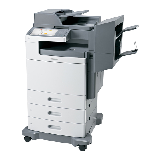
Next The X792 represents the latest in Lexmark printer innovation, including a full-color eTask touch screen with improved messaging and animation, standard 160 GB or higher hard drive, enhanced security features, remote operator panel access and control, customizable reports, and access to the growing list of downloadable and Go Back customizable solutions. -
Page 30: Printer Configurations
If you purchased a multifunction printer (MFP) that scans, copies, and faxes, you may need additional furniture. For more information, see Go Back www.lexmark.com/multifunctionprinters. Some options may not be available for all models. Automatic Document Feeder (ADF) -
Page 31: Options And Features
7562 Previous Options and features Lexmark X792 printers support only Lexmark X792 paper-handling options. These options are not compatible with any other Lexmark printer. Next Some of the following options are not available in every country or region. Available internal options Go Back •... - Page 32 7562 Notes: Previous • Using a power converter or inverter is not recommended. • The X790 series printers are ENERGY STAR qualified. • All models ship with Sleep Mode set to On. Next Electrical specifications Low-voltage models Go Back • 100 to 110 V ac at 50 to 60 hertz (Hz) nominal •...
- Page 33 *In some cases, performance specifications (such as paper OCF, EP cartridge usage) are measured at an ambient condition. Performance The X792 printers support up to 50 ppm maximum print, copy, and scan speeds. Performance speed depends on: • Interface to the host (USB, serial, parallel, network) •...
-
Page 34: Paper Sizes Supported By The Printer
7562 Duty cycle Previous • 2,500–17,000 pages per month (recommended) • 150,000 pages per month (maximum) Memory configuration Next 1GB standard memory. Optional memory is available in 256MB, 512MB, and 1GB 200-pin X64 DDR2 SO- DIMM. There is only one DIMM slot available for optional memory. Go Back Supported paper sizes, types, and weights Paper sizes supported by the printer... -
Page 35: Paper Types And Weights Supported By The Printer
WILL NOT be stapled. Paper size not supported for offset or stapling in the finishing options. Supported by X792 models only. This size setting formats the page for 216 x 356 mm (8.5 x 14 in.) unless the size is specified by the software application. -
Page 36: Paper Types And Weights Supported By The Output Bins
For more information, see the Card Stock & Label Guide available on the Lexmark Web site at http://support.lexmark.com. Use envelopes that lie flat when individually placed facedown on a table. -
Page 37: Paper Characteristics
Paper characteristics The following paper characteristics affect print quality and reliability. Consider these characteristics when evaluating new paper stock. For detailed information, see the Card Stock & Label Guide available on the Lexmark Web site at http:// support.lexmark.com. Weight The printer can automatically feed paper weights from 60 to 220 g/m (16 to 58 lb bond) grain long. -
Page 38: Unacceptable Paper
7562 Fiber content Previous Most high-quality xerographic paper is made from 100% chemically pulped wood. This content provides the paper with a high degree of stability resulting in fewer paper feeding problems and better print quality. Paper containing fibers such as cotton possesses characteristics that can result in degraded paper handling. Unacceptable paper Next The following papers are not recommended for use with the printer:... -
Page 39: Data Security Notice
7562 Previous Data security notice This printer contains various types of memory that are capable of storing device and network settings, information from embedded solutions, and user data. The types of memory, along with the types of data stored by each, are described below. Next •... -
Page 40: Acronyms
7562 Previous Acronyms ASIC Application-Specific Integrated Circuit BLDC Brushless DC Motor Black Only Retract Next Cyan Cyclic Redundancy Check Customer Setup Go Back DIMM Dual Inline Memory Module DRAM Dynamic Random Access Memory Enhanced Data Out Electrophotographic Process EPROM Erasable Programmable Read-Only Memory Electrostatic Discharge Field Replaceable Unit Gigabyte... -
Page 41: Diagnostic Information
7562 2. Diagnostic information Previous Next CAUTION Remove the power cord from the electrical outlet before you connect or disconnect any cable or electronic card or assembly for personal safety and to prevent damage to the printer. Go Back CAUTION The printer weight is greater than 32 kg (70 lb) and requires three or more trained personnel to move it safely. -
Page 42: Error Code Divisions
7562 Error code divisions Previous Error codes identifications have changed for this product. The following chart identifies some of the new code numbers that should be consistent across product lines. Next Range Description Go to page… Text prompts User prompts without code numbers “User prompts”... -
Page 43: Security Reset Jumper
7562 Security reset jumper Previous The Security Reset Jumper is available on all high-end printer and MFP models. Each device contains a hardware jumper with which an administrator can: Next • Erase all security templates, building blocks, and access controls that a user has defined (i.e. the factory default configuration);... -
Page 44: Paper Jams
7562 Previous Paper jams Understanding jam numbers and locations When a jam occurs, a message indicating the jam location appears on the display. To resolve any paper jam Next message, you must clear all jammed paper from the paper path. Go Back Area Jam number... -
Page 45: Paper Jam
7562 Previous Area Jam number What to do 280–291 Remove all paper from the ADF, and then remove the “280–289 paper jams” on jammed paper. page 2-22 Next 200 paper jam Open the left access door. Go Back Firmly grasp the jammed paper, and then gently pull it out. Note: Make sure all paper fragments are removed. - Page 46 7562 Previous Error code Description Action 200.04 Input sensor flag broke early. 1. Clear away anything in the paper path that might cause the paper to jam. Possible cause: 2. Be sure the paper settings match the media. • Incorrect paper settings 3.
- Page 47 7562 Previous Error code Description Action 200.35, Near narrow media sensor does not 1. Clear away anything in the paper path that might 200.37 break or breaks late. cause the paper to jam. 2. Be sure the paper settings match the media. •...
-
Page 48: Paper Jam
7562 Previous Error code Description Action 200.48 Narrow media sensor is never made “200.43” on page 2-7. or is made late. 200.49 S1 sensor is made when printer tries 1. Clear away anything in the paper path that might Next to print from an idle state. - Page 49 7562 Previous Error code Description Action 201.03 Bubble sensor is never made or is 1. Clear away anything in the paper path that might made late. cause the paper to jam. 2. If clearing a paper jam does not fix the problem, Possible causes: go to “201.03, 201.05, 201.07, 201.08—Paper...
-
Page 50: Paper Jams
7562 202–203 paper jams Previous Paper jam in the standard exit bin: Firmly grasp the paper on each side, and then gently pull it out. Note: Make sure all paper fragments are removed. Next Go Back From the operator panel, touch Continue, jam cleared. Paper jam in the fuser: Open the left access door. - Page 51 7562 Additional checks—202–203 paper jams Previous Error code Description Action 202.01 Exit sensor is made when printer tries 1. Check for anything in the paper path that might to print from an idle state. cause the paper to jam. Next 2.
- Page 52 7562 Previous Error code Description Action 202.33 Bin-full sensor is never made or is 1. Clear away anything in the paper path that might made late. cause the paper to jam. 2. If clearing a paper jam does not fix the problem, go to “Pick arm stuck down service check”...
-
Page 53: Paper Jams
7562 Previous Error code Description Action 203.03 Redrive bubble sensor is never made 1. Clear away anything in the paper path that might or is made late. cause the paper to jam. 2. If clearing a paper jam does not fix the problem, Possible cause: Faulty redrive bubble go to “Redrive bubble sensor service check”... - Page 54 7562 Additional checks—230 paper jam Previous Error code Description Action 231.01 D1 sensor is made when printer tries 1. Check for anything in the paper path that might to print from an idle state. cause the paper to jam. Next 2.
-
Page 55: 24X Paper Jam
7562 Previous 232.04 D2 sensor broke early. The D2 sensor may not be functioning properly. Go “D1 and D2 sensor service check” on Possible causes: page 2-173. • Damaged D2 sensor • Faulty fuser • Faulty system board Next 232.05, D2 sensor never broke. - Page 56 7562 Additional checks—24x paper jam Previous Error code Description Action 241.01 S1 sensor is made when printer 1. Clear away anything in the paper path that might powers up or covers are closed. cause the paper to jam. Next 2. If clearing a paper jam does not fix the problem, Possible causes: go to “Input, S1, narrow media, and near...
- Page 57 7562 Previous Error code Description Action 241.21, Tray 1 motor stalled. 1. Remove all media present in the paper path. 241.22 2. Be sure the paper settings match the media. Possible causes: 3. Flex the media, and stack it flat in the tray or •...
- Page 58 7562 Previous Error code Description Action 243.01 Tray 3 sensor is reached during POR 1. Clear anything in the paper path that might or after clearing the paper jam, tray 3 cause the paper to jam. sensor is still triggered. 2.
- Page 59 7562 Previous Error code Description Action 244.01 Tray 4 sensor is reached during POR 1. Clear anything in the paper path that might or after clearing the paper jam, tray 4 cause the paper to jam. sensor is still triggered. 2.
- Page 60 7562 Previous Error code Description Action 245.01 Tray 5 sensor is reached during POR 1. Clear anything in the paper path that might or after clearing the paper jam, tray 5 cause the paper to jam. sensor is still triggered. 2.
-
Page 61: Paper Jam
7562 250 paper jam Previous Remove all paper from the multipurpose feeder. Grasp the jammed paper on each side, and then gently pull it out. Next Go Back Note: Make sure all paper fragments are removed. Reload paper into the multipurpose feeder, and then adjust the paper guides. From the operator panel, touch Continue, jam cleared. -
Page 62: Paper Jams
7562 280–289 paper jams Previous An ADF maintenance kit is available if the printer is experiencing scan image quality issues such as streaking, gray images in the same place on flatbed scans, in addition to the paper feed issues listed in the checks below. Remove all original documents from the ADF. - Page 63 7562 Previous Error code Description Action 283.01 Scanner static jam—scanning sensor. 1. Remove all media present in media path. 2. Check ADF scanning sensor for proper operation. Go to “283.01—Sensor (1st scan) static jam service check” on page 2-128. Next 283.03 Scanner ADF feed jam.
-
Page 64: Output Option Paper Jams
7562 Previous Output option paper jams 400–403 paper jams Additional checks—400–403 paper jams Next Error code Description Action Go Back 400.20 - 400.32 HTU motor error 1. POR the machine. 2. If the problem persists, replace the HTU transport motor. See “HTU transport motor removal”... - Page 65 7562 Previous Error code Description Action 402.05/402.07 HTU output sensor breaks late or 1. Clear away anything in the paper path that might never breaks paper jam cause the paper to jam. 2. Be sure the paper settings match the media. Possible cause: 3.
-
Page 66: Paper Jams
7562 431–432 paper jams Previous Additional checks—431–432 paper jams Error code Description Action Next 431.01 5-bin mailbox input sensor is made 1. Clear away anything in the paper path that might when the printer powers up. cause the paper to jam. 2. -
Page 67: Paper Jams
7562 Previous Error code Description Action 432.04 5-bin mailbox passthru sensor early 1. Clear away anything in the paper path that might leaving paper jam. cause the paper to jam. 2. Be sure the paper settings match the media. Possible cause: 3. - Page 68 7562 Previous Error code Description Action 450.34 Finisher/Stacker page ID not clear. 1. Turn the machine off/on. 2. If the problem persists, replace the Finisher/ Stacker controller card. See “Finisher or stacker controller card assembly removal” Next on page 4-335. 450.35 Finisher/Stacker DMID command is 1.
- Page 69 7562 Previous Error code Description Action 453.31 Finisher/Stacker left tamper does not 1. Check all the connections on the output option move to home position failure. controller card. 2. Check the tamper drive belt for damage and The Finisher/Stacker sensor (left replace if needed.
- Page 70 7562 Previous Error code Description Action 455.30 Finisher/Stacker staple ready home 1. Check all the connections on the controller card position jam. and the stapler assembly. 2. Remove the staple cartridge and remove all The sensor (self priming) within the jammed staples.
-
Page 71: Paper Jams
7562 Previous Error code Description Action 456.05, Finisher stapler home sensor breaks 1. Clear away anything in the paper path that might 456.07 late or never breaks paper jam. cause the paper to jam. 2. Be sure the paper settings match the media. 3. - Page 72 7562 Additional checks—461 paper jams Previous Error code Description Action 461.01 Hole punch sensor is made when the 1. Clear away anything in the paper path that might printer powers up cause the paper to jam. Next 2. If clearing a paper jam does not fix the problem, go to “461.01 - 461.08—Hole punch sensor error service check”...
-
Page 73: Print Quality
7562 Previous Print quality Note: These symptoms may require replacement of one or more CRUs (Customer Replaceable Units) designated as supplies or maintenance items, which are the responsibility of the customer. With the customer's permission, you may need to install a developer (toner) cartridge or photoconductor unit. Next Service tip: Before troubleshooting any print quality problems, do the following: Print a menu settings page, and then check the life status of all supplies. -
Page 74: Background (Fog)
7562 Previous Symptom Action Print is too light Go to “Print is too light” on page 2-44 Random marks Go to “Random marks” on page 2-45 Repeating defects Go to “Repeating defects” on page 2-46 Next Shadow images Go to “Shadow images”... - Page 75 7562 Additional checks—background Previous Step Questions / actions Replace the print cartridge. Problem solved. Go to step 2. Next Does this fix the problem? Check the high voltage contact from the HVPS to the Replace the ITU Go to step 3. transfer module.
-
Page 76: Blank Page
7562 Blank page Previous Try one or more of the following: • MAKE SURE THERE IS NO PACKING MATERIAL LEFT ON THE PRINT CARTRIDGE Remove the print cartridge and make sure the packing material is properly removed. Reinstall the print Next cartridge. -
Page 77: Blurred Or Fuzzy Print
7562 Blurred or fuzzy print Previous Try one or more of the following: • CHECK THE EP DRIVE ASSEMBLY AND TRANSFER MODULE Blurred or fuzzy print is usually caused by a problem in the EP drive assembly or in the transfer module. Next Check the EP drive assembly and transfer module for correct operation. -
Page 78: Colors Not Properly Aligned
7562 • For Windows users, specify the size from Print Properties. Previous • For Macintosh users, specify the size from the Page Setup dialog. • RESEAT THE CARTRIDGES Colors not properly aligned Next Go Back ABCDE ABCDE ABCDE ABCDE Color has shifted outside of the appropriate area or has been superimposed over another color area. Try one or more of the following: •... -
Page 79: Horizontal Banding
7562 Horizontal banding Previous Leading edge Next Go Back Trailing edge Try one or more of the following: • MAKE SURE THERE IS NO DEFECTIVE PRINT CARTRIDGE Measure the distance between repeating bands. If the distance between bands either 27 or 36mm, then replace the defective print cartridge. -
Page 80: Light Colored Line, White Line, Or Incorrectly Colored Line
7562 Additional checks—horizontal lines Previous Step Questions / actions Next 1. Check the media condition. Go to step 2. Problem solved. 2. Load new, dry, recommended media. 3. Re-print the defective image. Does the error continue? Go Back 1. Check the media transfer route. Go to step 3. -
Page 81: Media Damage
7562 Media damage Previous Leading edge Next Go Back Trailing edge Additional checks—media damage Step Questions / actions Check printer installation placement. Go to step 2. Correct the installation Check the installation surface for irregularities. placement. Check for missing printer foot. Is the setup surface normal? Check the media feed. -
Page 82: Mottle (2-5Mm Speckles)
7562 Mottle (2–5mm speckles) Previous Leading edge Next Go Back Trailing edge The problem is caused by the photoconductor being dirty. Keep running prints through, and the problem normally clears up. If the problem persists, replace the cartridge of the color causing the spots. Paper curl •... - Page 83 7562 Make sure the paper type and weight settings match the paper loaded in the tray: Previous From the printer Paper menu, check the Paper Type and Paper Weight settings. Before sending the job to print, specify the correct type settings from the computer: •...
-
Page 84: Print Is Too Dark
7562 Print is too dark Previous Next Go Back Try one or more of the following: • LOAD PAPER FROM A FRESH PACKAGE The paper may have absorbed moisture due to high humidity. Store paper in its original wrapper until you use it. -
Page 85: Random Marks
7562 Make sure the paper type setting matches the paper loaded in the tray: Previous From the operator panel Paper menu, check the Paper Type setting. Before sending the job to print, specify the correct type setting from the computer: •... -
Page 86: Repeating Defects
7562 Repeating defects Previous Next Go Back Print quality defect locator chart The printer has an internal copy of the defect locator chart under the Help Menu. From the home screen, navigate to: > Help > Print Defects Verify the proper image size by measuring any of the marks on the printed chart and comparing them to the corresponding measurement in the chart. -
Page 87: Shadow Images
7562 Shadow images Previous Leading edge Next Go Back Trailing edge Try one or more of the following: • CHECK THE PAPER TYPE AND WEIGHT SETTINGS Make sure the paper type and weight settings match the paper loaded in the tray or feeder: From the operator panel Paper menu, check the Paper Type and Paper Weight settings. -
Page 88: Skew
7562 Skew Previous Leading edge Next Go Back Trailing edge CHECK THE PRINTER SKEW Measure from the edge of the paper to the black line to find L1, L2, T1, T2, R1, R2, B1, and B2 as shown below: 2. Determine if the printer meets the skew specifications based on the values listed on the table. Skew Specification (L2-L1) (R2-R1) - Page 89 7562 Additional checks—skew Previous Step Questions / actions 1. Check printer installation placement. Go to step 2. Correct the Next installation 2. Check the installation surface for irregularities. placement. 3. Check for damaged printer caster. Is the setup surface normal? Go Back 1.
-
Page 90: Solid Color Or Black Pages
7562 Solid color or black pages Previous Next Go Back • MAKE SURE THE PRINT CARTRIDGES ARE INSTALLED CORRECTLY, ARE NOT DEFECTIVE AND NOT LOW ON TONER Remove and reinstall the print cartridges. Service tip: A solid color page is generally caused by a problem in the high voltage system or an incorrect high voltage in the printing process resulting in toner development on the entire photoconductor drum. -
Page 91: Toner Rubs Off
7562 Toner rubs off Previous Leading edge Next Go Back Trailing edge Try one or more of the following: • CHECK THE PAPER TYPE AND WEIGHT SETTINGS Make sure the paper type and weight settings match the paper loaded in the tray or feeder: From the operator panel Paper menu, check the Paper Type and Paper Weight settings. -
Page 92: Transparency Print Quality Is Poor
7562 Transparency print quality is poor Previous Try one or more of the following: • CHECK THE TRANSPARENCIES Use only transparencies that meet the printer specifications. Next • CHECK THE PAPER TYPE SETTINGS Make sure the paper type settings match the paper loaded in the tray or feeder: Go Back From the operator panel Paper menu, check the Paper Type setting. -
Page 93: Vertical Lines
7562 Vertical lines Previous Leading edge Next Go Back Trailing edge Step Check 1. Check the media condition. Go to step 2. Problem solved. 2. Load new, dry, recommended media. 3. Re-print the defective image. Does the error continue? Are the media transfer route and the media path free Go to step 3. -
Page 94: Adf & Scanner Print Quality
7562 Previous ADF & scanner print quality Note: Get a printout as a base, and then follow the symptom table to identify the possible failing FRU. If the printer is exhibiting paper feed symptoms such as ADF paper jams, skewing, and ADF misfeeds in addition Next to the scan image quality symptoms, an ADF maintenance kit is available to address multiple ADF symptoms. -
Page 95: Vertical Lines (Process Direction Using The Adf)
7562 Vertical lines (process direction using the ADF) Previous Step Check Next Check the small platen glass on the scanner unit Clean or replace Go to step 2. assembly. the scanner platen glass Is the large and small platen glass contaminated or cover. - Page 96 7562 Previous Step Check Perform a print test using the scanner CCD assembly. Replace the Problem solved. scanner CCD Does the error continue? assembly. Next Go to “ADF duplex CCD assembly Go Back removal” on page 4-176. Perform a print test using the flatbed scanner assembly. Replace the Problem solved.
-
Page 97: Skew (Using Adf)
7562 Skew (using ADF) Previous The printed image is not paralleled with both sides of the media. Step Check Next Check printer installation placement. Go to step 2. Correct the installation Go Back Check the installation surface for irregularities. placement. Check for damaged printer caster. -
Page 98: Media Damage (Using Adf)
7562 Media damage (using ADF) Previous Step Check Next Properly load document into the ADF unit assembly and Go to step 2. Problem solved. ensure all guides are set correctly. Re-print the defective image. Go Back Does the error continue? Check for obstructions in the area of the media feed Go to step 3. -
Page 99: User Messages
7562 Previous User messages User prompts Next Error code Action Close Front Door Close the front door securely. If you continuously get this error, then the interlock switch may be bad. See “Interlock switch error service check” on page 2-181. Go Back Close Side Door Close the side door securely. - Page 100 7562 Previous Error code Action Load Manual <size> If paper loaded is in the manual feeder, the job continues. If paper is not in the feeder, pressing Select indicates to the printer it should search for a source with the proper size. Additional messages may include: Next •...
-
Page 101: User Attendance Messages (0-99)
7562 User attendance messages (0–99) Previous Error code Action 31 Defective or Missing • Reseat the specified print cartridge. <color> Cartridge Next • Inspect the print cartridge contacts for damage/contamination. Replace the print cartridge if defective. • Inspect the cartridge cable connection. Properly connect the cable if not connected properly. - Page 102 7562 Previous Error code Action 37 Insufficient memory, • The printer deleted some held jobs in order to process current jobs. Some Held Jobs Were • Select Continue to clear the message. Not Restored • If this does not fix the problem, replace the system board. See “System board removal”...
- Page 103 7562 Previous Error code Action 54 Serial option <x> • Make sure the serial link is set up correctly and the appropriate cable is in use. error • Make sure the serial interface parameters (protocol, baud, parity, and data bits) are set correctly on the printer and host computer.
- Page 104 7562 Previous Error code Action 58 Too Many Trays 1. Turn off and unplug the printer. Attached 2. Remove options until the supported number of options for that model. Models C734 supports three options and models C736 supports four options. 3.
- Page 105 7562 Previous Error code Action • Show Me, View Supplies, and Tell Me More displays additional information. 80 Replace Fuser • If the fuser is not near the end of life and the message persists, the printer likely needs service. Note: Reseat the connectors behind the fuser.
- Page 106 7562 Previous Error code Action 82 Replace Waste • Replace the waste toner box using the instruction sheet that comes with the replacement Toner waste toner box. • Ensure that there is no interference between the waste toner box and the printer. •...
- Page 107 7562 Previous Error code Action 84 <color> PC Unit • Scroll down the operator panel to see if the printer is showing that all four of the PC units Missing are missing. If so, check the HVPS cable between the system board and the HVPS. Ensure that the cable is not plugged in backwards on the HVPS.
-
Page 108: Service Errors
7562 Previous Service errors Printer hardware errors (100–199) Next Error code Description Action An error has occurred in the • POR the printer. Printhead Error printhead. • If the error message persists, go to “110.xx— Go Back Printhead error service check” on page 2-76. - Page 109 7562 Previous Error code Description Action 145.01–145.19 An error has occurred in the all-color • POR the printer. Retract Motor Error retract motor. • If the error message persists, go to “125.xx, 145.xx—ITU error service check” on page 2-82. Next 146.01–146.22 Tray 1 motor has failed.
-
Page 110: Adf And Flatbed Scanner Errors (800-899)
7562 ADF and flatbed scanner errors (800–899) Previous Error code Description Action 840.01 The scanner has been manually Enter the configuration mode to re-enable the disabled scanner. Next 840.02 The scanner has automatically been Enter the configuration mode to re-enable the disabled by the controller scanner. -
Page 111: Firmware And/Or System Electronics (900-999))
7562 Firmware and/or system electronics (900–999)) Previous Error code Description Action 900.00–900.99 An unrecoverable RIP software error • Go to “Steps before starting the 9yy service (except 900.05) occurred while an unknown process checks” on page 2-156. Next Software Error was running. - Page 112 7562 Previous Error code Description Action 938.21 A staging motor failure occurred. • POR the printer. Electronics Hardware • If the error message persists, go to “147.xx— Error Staging motor error service check” on page 2-96. Next 938.22 A printhead failure error occurred. •...
- Page 113 7562 Previous Error code Description Action 956.xx except for 956.02 A processor failure has occurred. • POR the printer. System Card Failure • If the error message persists, replace the system board. See “System board removal” on page 4-149. Next 956.02 The processor fan has failed.
- Page 114 7562 Previous Error code Description Action 990.00–990.29 An option error has occurred. Go to “990.xx—POST error service check” on Option Error page 2-168 991.00–991.99 The specified device has detected an • POR the printer. Next <device> Error error. • If the error message persists, replace the system board.
-
Page 115: Symptoms
7562 Previous Symptoms Symptom table—base printer Next Symptom Action Dead printer Go to “Dead printer service check” on page 2-175. Tray linking will not work. Go to “Tray linking service check” on page 2-200. Go Back Paper pick mechanism—pick arm is stuck Go to “Pick arm stuck down service check”... -
Page 116: Service Checks
7562 Previous Service checks 110.xx—Printhead error service check Next Step Questions / actions View the Event Log: Replace the printhead. See Go to step 2. “Printhead removal, Go Back 1. Turn off the printer, press and hold 3 and installation, and 6 and turn on the printer. - Page 117 7562 Previous Step Questions / actions Measure the resistance across fuse F11 on Replace the system board. Go to step 5. the system board. “System board removal” on page 4-149. Next Go Back Is the fuse blown? Perform the printhead verification to check Replace the printhead.
-
Page 118: Xx-Motor (Fuser) Error Service Check
7562 120.xx—Motor (fuser) error service check Previous Step Questions / actions Turn the printer off, open the system board Go to step 2. Reseat the cable. shield, and remove the RIP card shield. Next Check the cable in connector JYF1 (BLDC Y &... -
Page 119: Xx-Fuser Error Service Check
7562 Previous Step Questions / actions Replace the fuser motor. See “Fuser drive Replace the system board. Problem solved. assembly removal” on page 4-61. “System board removal” on page 4-149. Does the problem reoccur? Next Go Back 121.xx—Fuser error service check Step Questions / actions Replace the fuser. - Page 120 7562 Previous Step Questions / actions Check the cable (E) on the LVPS for proper Go to step 5. Reseat the cable. connection. Next Go Back Is the cable properly connected? Check the cable on the LVPS for damage. Replace the Fuser and Go to step 6.
- Page 121 7562 Previous Step Questions / actions Open the left access door, remove the two Go to step 7. Reseat the cable. screws (A), and pull out the fuser autoconnect enough to check the cable for proper connection. Next Go Back Is the cable properly connected? Check the cable for damage.
-
Page 122: Xx, 145.Xx-Itu Error Service Check
7562 125.xx, 145.xx—ITU error service check Previous Step Questions / actions Replace the ITU assembly. See “ITU Problem solved. Go to step 2. assembly removal” on page 4-72. Next Does the error clear? Turn the printer off, open the system board Go to step 3. -
Page 123: Xx-Lvps Error Service Check
7562 126.xx—LVPS error service check Previous Step Questions / actions Turn the printer off, open the system board Go to step 2. Reseat the cables. shield, and remove the RIP card shield. Next Check the cables in connector JLVPS1 and J17 (E) for proper connection to the system board. -
Page 124: Xx-Cartridge Sensor Error Service Check
7562 133.xx—Cartridge sensor error service check Previous Step Questions / actions a. Power off the printer. Replace the Go to step 2. cartridge. b. Enter the Diagnostics mode, (press and hold 3 and 6, while Next turning on the printer). c. - Page 125 7562 Previous Step Questions / actions Error code Sensor Next 133.01 133.02 133.03 Go Back 133.04 Does the sensor go from “Open” to “Close?” Turn the printer off and open the system board shield. Check the Go to step 3. Reseat the cables in the indicated connectors for proper connection to the cable.
- Page 126 7562 Previous Step Questions / actions Check the cables in the indicated connectors for proper connection to Go to step 4. Reseat the the system board. cable. Next Go Back 133.01 Black—D (JCMKM1) 133.02 Cyan—C (JCMCY1) 133.03 Magenta—D (JCMKM1) 133.04 Yellow—C (JCMCY1) Are the cables properly connected? Check the cables in connectors JCMKM1 and JCMCY1 for damage, Replace the...
- Page 127 7562 Previous Step Questions / actions Replace the indicated cartridge memory block and cable. Problem Replace the solved. system board. “System Error Memory block Cable board code Next removal” on page 4-149. 133.01 Black JCMKM1 133.02 Cyan JCMCY1 Go Back 133.03 Magenta JCMKM1...
- Page 128 7562 Previous Step Questions / actions 3. Rotate the developer input gear clockwise until the tab (H) is up against the tab on the larger gear (J). Next Go Back Print two demo pages: 1. Replace all cartridges. 2. Turn on the machine. 3.
-
Page 129: Xx-Black Cartridge Motor Error Service Check
7562 141.xx—Black cartridge motor error service check Previous Step Questions / actions Turn the printer off, open the system board Go to step 2. Reseat the cable. shield, and remove the RIP card shield. Next Check the cable in the connector JKI1 for proper connection to the system board. -
Page 130: Xx-Cyan Cartridge Motor Error Service Check
7562 Previous Step Questions / actions Remove the system board cage. See Go to step 5. Reseat the cable. “System board cage with board removal” on page 4-157. Check the cable connected to the black Next cartridge motor. Go Back Is the cable connected properly? Replace the EP drive assembly. - Page 131 7562 Previous Step Questions / actions Measure the resistance across the fuse F16 Replace the system board. Go to step 4. on the system board. “System board removal” on page 4-149. Next Go Back Is the fuse blown? Remove the system board cage. See Go to step 5.
-
Page 132: Xx-Magenta Cartridge Motor Error Service Check
7562 143.xx—Magenta cartridge motor error service check Previous Step Questions / actions Turn the printer off, open the system board Go to step 2. Reseat the cable. shield, and remove the RIP card shield. Next Check the cable in the connector JCM1 for proper connection to the system board. -
Page 133: Xx-Yellow Cartridge Motor Error Service Check
7562 Previous Step Questions / actions Remove the system board cage. See Go to step 5. Reseat the cable. “System board cage with board removal” on page 4-157. Check the cable connected to the magenta Next cartridge motor. Go Back Is the cable connected properly? Replace the EP drive assembly. - Page 134 7562 Previous Step Questions / actions Measure the resistance across the fuse F12 Replace the system board. Go to step 4. on the system board. “System board removal” on page 4-149. Next Go Back Is the fuse blown? Remove the system board cage. See Go to step 5.
-
Page 135: Xx-Autocomp (Tray 1) Motor Error Service Check
7562 146.xx—Autocomp (tray 1) motor error service check Previous Step Questions / actions Turn the printer off, and open the system Go to step 2. Reseat the cable. board shield. Check the cable in connector Next JTRAY1 (A) for proper connection to the system board. -
Page 136: Xx-Staging Motor Error Service Check
7562 147.xx—Staging motor error service check Previous Step Questions / actions Turn the printer off, and open the system Go to step 2. Reseat the cable. board shield. Check the cable in connector Next JSTAG1 for proper connection to the system board. -
Page 137: Xx-Paper Path Redrive Motor Error Service Check
7562 149.xx—Paper path redrive motor error service check Previous Step Questions / actions Turn the printer off, and open the system Go to step 2. Reseat the cable. board shield. Check the cable in connector Next JRDR1 for proper connection to the system board. - Page 138 7562 Previous Step Questions / actions Turn the printer off, and open the system Go to step 3. Reseat the cable. board shield. Check the cable in connector JDUPL1 for proper connection to the system board. Next Go Back Is the cable properly connected? Check the cable for damage.
-
Page 139: Xx-Itu Motor Error Service Check
7562 151.xx—ITU motor error service check Previous Step Questions / actions Turn the printer off, open the system board Go to step 2. Reseat the cable. shield, and remove the connector shield. Next Check the cable in connector JKI1 for proper connection to the system board. -
Page 140: Xx-Main Fan Error Service Check
7562 171.xx—Main fan error service check Previous Step Questions / actions Turn the printer off, and open the system Go to step 2. Reseat the cable. board shield. Check the cable in connector Next JM1 for proper connection to the system board. -
Page 141: Xx-Blower Fan Error Service Check
7562 173.xx—Blower fan error service check Previous Step Questions / actions Turn the printer off, and open the system Go to step 2. Reseat the cable. board shield. Check the cable in connector Next JBLW1 for proper connection to the system board. -
Page 142: Paper Jam Error Service Check
7562 200.02—Paper Jam error service check Previous Step Questions / actions Open the left access door. Check the input Replace the input sensor. Go to step 2. flag (A) for damage. “Sensor (input, S1, Next narrow media, near narrow media) removal” on page 4-137. -
Page 143: 200.08-Paper Jam Error Service Check
7562 200.03, 200.08—Paper Jam error service check Previous Step Questions / actions Remove the input tray. Replace the pick tires. See Go to step 2. “Pick rolls removal” on Next page 4-120. Are the pick tires worn? Open the left access door. Check the input Replace the input sensor. -
Page 144: 200.07-Paper Jam Error Service Check
7562 Previous Step Questions / actions Check the cable in connector JPP2 for any Replace the paper path Go to step 6. other damage. cable. See “Paper path cables” on page 7-68. Next Is the cable damaged? Remove the staging deflector assembly. See Go to step 7. -
Page 145: Paper Jam Error Service Check
7562 Previous Step Questions / actions Remove the staging deflector assembly. See Go to step 6. Reseat the cable. “Staging deflector assembly removal” on page 4-138. Next Is the cable connected correctly? Replace the input sensor. See “Sensor Replace the system board. Problem solved. - Page 146 7562 Previous Step Questions / actions Remove the staging deflector assembly. See Reseat the sensor and add Contact your next level of “Staging deflector assembly removal” on a sensor retainer. See support. page 4-138. “Sensor (input, S1, narrow media, near Next narrow media) removal”...
-
Page 147: 200.38-Paper Jam Error Service Check
7562 200.33, 200.38—Paper Jam error service check Previous Step Questions / actions Remove the input tray. Replace the pick tires. See Go to step 2. “Pick rolls removal” on Next page 4-120. Are the pick tires worn? Open the left access door. Check the near Replace the near narrow Go to step 3. -
Page 148: 200.37-Paper Jam Error Service Check
7562 Previous Step Questions / actions Check the cable in connector JPP2 for any Replace the paper path Go to step 6. other damage. cable. See “Paper path cables” on page 7-68. Next Is the cable damaged? Remove the staging deflector assembly. See Go to step 7. -
Page 149: Paper Jam Error Service Check
7562 Previous Step Questions / actions Remove the staging deflector assembly. See Go to step 6. Reseat the cable. “Staging deflector assembly removal” on page 4-138. Is the cable connected correctly? Next Replace the near narrow media sensor. See Replace the system board. Problem solved. - Page 150 7562 Previous Step Questions / actions Remove the staging deflector assembly. See Reseat the sensor and add Contact your next level of “Staging deflector assembly removal” on a sensor retainer. See support. page 4-138. “Sensor (input, S1, narrow media, near Next narrow media) removal”...
-
Page 151: 200.48-Paper Jam Error Service Check
7562 200.43, 200.48—Paper Jam error service check Previous Step Questions / actions Remove the input tray. Replace the pick tires. See Go to step 2. “Pick rolls removal” on Next page 4-120. Are the pick tires worn? Open the left access door. Check the narrow Replace the narrow media Go to step 3. -
Page 152: 200.47-Paper Jam Error Service Check
7562 Previous Step Questions / actions Check the cable in connector JPP2 for any Replace the paper path Go to step 6. other damage. cable. See “Paper path cables” on page 7-68. Next Is the cable damaged? Remove the staging deflector assembly. See Go to step 7. -
Page 153: Paper Jam Error Service Check
7562 Previous Step Questions / actions Remove the staging deflector assembly. See Go to step 6. Reseat the cable. “Staging deflector assembly removal” on page 4-138. Next Is the cable connected correctly? Replace the near narrow media sensor. See Replace the system board. Problem solved. - Page 154 7562 Previous Step Questions / actions Open the left access door, remove the two Go to step 5. Reseat the cable. screws (A), and pull out the fuser autoconnect enough to check the cable for proper connection. Next Go Back Is the cable connected correctly? Check the cable for damage.
-
Page 155: Paper Jam Error Service Check
7562 202.32—Paper Jam error service check Previous Step Questions / actions Is the bin-full flag damaged? Replace the bin-full flag. Go to step 2. “Bin-full flag Next removal” on page 4-33. Go Back Remove the top cover assembly. Reseat the sensor. Contact your next level of support. -
Page 156: Paper Jam Error Service Check
7562 241.02—Paper Jam error service check Previous Step Questions / actions Open the left access door. Check the S1 Replace the S1 sensor. Go to step 2. sensor flag (B) for damage. “Sensor (input, S1, Next narrow media, near narrow media) removal” on page 4-137. -
Page 157: Paper Jam (550-Sheet/2000-Sheet Input Option) Service Check
7562 242.01, 243.01, 244.01, 245.01 —Paper Jam (550-sheet/2000-sheet input option) Previous service check Step Questions / actions Next Check for any obstruction on the paper path. Go to step 2. Clear paper path for obstructions. Is the paper path free of obstruction? Go Back Check if the jam clearance cover can close Go to step 3. -
Page 158: Option) Service Check
7562 Previous Step Questions / actions For 550-sheet input option: For 550-sheet input option: Problem solved. Replace the 550-sheet Replace the controller card assembly. See drawer assembly. See “550-sheet tray controller card assembly “550-sheet drawer removal” on page 4-241. Next assembly removal”... - Page 159 7562 Previous Step Questions / actions Check if the pass thru sensor is seated Go to step 4. For 550-sheet input option: correctly and not damage. Replace the pass thru sensor. See “550-sheet tray pass thru sensor Next removal” on page 4-249.
-
Page 160: Paper Jam (550-Sheet/2000-Sheet Input Option) Service Check
7562 Previous Step Questions / actions For 550-sheet input option: Replace the Go to step 8. Problem solved. controller card assembly. See “550-sheet tray controller card assembly removal” on page 4-241. Next For 2000-sheet input option: Replace the controller card assembly. See “2000-sheet Go Back high-capacity feeder controller card... - Page 161 7562 Previous Step Questions / actions Check if the pass thru sensor is seated Go to step 4. Install the pass thru sensor correctly and the sensor flag can move back correctly. to its original position when it is triggered. Next Go Back Is the pass-thru sensor free of...
-
Page 162: 250.22-Mpf Motor Error Service Check
7562 Previous Step Questions / actions 1. Check the pick assembly for mechanical Go to step 7. For 550-sheet input option: wear or damage. Replace the pick assembly. “550-sheet tray pick 2. Check if the pick arm spring is not assembly removal”... - Page 163 7562 Previous Step Questions / actions Turn the printer off, and open the system Go to step 4. Reseat the cable. board shield. Check the cable in connector JTRAY1 for proper connection to the system card. Next Go Back Is the cable connected correctly? Check the cable in connector JTRAY1 for Replace the Tray 1 Go to step 5.
- Page 164 7562 Previous Step Questions / actions Is the MPF drive assembly damaged? Replace the MPF drive Go to step 8. assembly. See “MPF drive assembly removal” on page 4-104. Next Go Back Replace the Input tray feed assembly. See… Replace the system board. Problem solved.
-
Page 165: Media Missing Jam Service Check
7562 280.06—Media missing jam service check Previous Step Check Next 1. Remove all documents from the ADF. Go to step 2. Problem solved. 2. Place an undamaged document in the ADF, and perform a ADF test. Does the error remain? Go Back Check the sensor (ADF document set) for Go to step 6. -
Page 166: Sensor (Adf Sheet Through) Static Jam Service Check
7562 282.01—Sensor (ADF sheet through) static jam service check Previous Step Check Next Check the media path. Go to step 2. Remove any media or media fragments. Is the media path free of media or media fragments? Go Back Check the sensor (ADF sheet through) for Go to step 4. - Page 167 7562 Previous Step Check Check the media path for contaminates. Go to step 4. Remove all contaminants from the media path. Is the media path free of excess media Next dust and foreign objects such as paper clips and staples? Check the ADF feed drive motor assembly for Replace the ADF feed Replace the connection.
-
Page 168: Sensor (1St Scan) Static Jam Service Check
7562 283.01—Sensor (1st scan) static jam service check Previous Step Check Next Check the media path. Go to step 2. Remove any media or media fragments. Is the media path free of media or media fragments? Go Back Check the sensor (ADF 1st scan) for proper Go to step 4. -
Page 169: Sensor (Adf 1St Scan) Late Jam Service Check
7562 283.03—Sensor (ADF 1st scan) late jam service check Previous Step Check Next Check the original document condition. Go to step 2. Remove damaged original document and replace with Is the original document free of paper a new undamaged original clips and staples as well as damage such document. -
Page 170: Sensor (2Nd Scan) Lingering Jam Service Check
7562 283.05—Sensor (2nd scan) lingering jam service check Previous Step Check Next Check the media size setup and tray guides Go to step 2. Replace the media, or for the ADF. change the media size setup. Does the media size in use, match the size set for the ADF? Go Back Check the original document condition. -
Page 171: Sensor (2Nd Scan) Static Jam Service Check
7562 284.01—Sensor (2nd scan) static jam service check Previous Step Check Next Check the media path. Go to step 2. Remove any media or media fragments. Is the media path free of media or media fragments? Go Back Check the sensor (2nd scan) for proper Go to step 4. -
Page 172: Sensor (Adf Media Exit) Late Jam Service Check
7562 284.03—Sensor (ADF media exit) late jam service check Previous Step Check Next Check the original document condition. Go to step 2. Remove damaged original document and replace with Is the original document free of paper a new undamaged original clips and staples as well as damage such document. -
Page 173: 285.03, 285.07-Sensor (Adf Media Exit) Static Jam Service Check
7562 285.01, 285.03, 285.07—Sensor (ADF media exit) static jam service check Previous Step Check Next Check the media path. Go to step 2. Remove any media or media fragments. Is the media path free of media or media fragments? Go Back Check the sensor (ADF media exit) for proper Go to step 4. -
Page 174: Sensor (Adf Media Exit) Late Jam Service Check
7562 285.05—Sensor (ADF media exit) late jam service check Previous Step Check Next Check the original document condition. Go to step 2. Remove damaged original document and replace with Is the original document free of paper a new undamaged original clips and staples as well as damage such document. -
Page 175: Adf Top Door Open Jam Service Check
7562 290.11—ADF top door open jam service check Previous Step Check Next 1. Remove all documents from the ADF. Go to step 2. Problem solved. 2. Place an undamaged document in the ADF, and perform an ADF test. Go Back Does the error remain? Check the sensor (ADF top door interlock) for Go to step 4. -
Page 176: Xx-Htu Input Sensor Error Service Check
7562 401.xx—HTU input sensor error service check Previous Step Questions / actions 1. Bring the printer up in Diagnostics menu (turn off Go to step 2. Problem solved. the printer, press and hold 3 and 6, turn on the Next printer, and hold the buttons until the splash screen appears). -
Page 177: Xx-Htu Output Sensor Error Service Check
7562 Previous Step Questions / actions Replace the HTU input sensor. See “HTU sensor Replace the HTU Problem solved. (input) removal” on page 4-404. controller card. “HTU controller card Next removal” on Does the error reoccur? page 4-369. Go Back 402.xx—HTU output sensor error service check Step Questions / actions... -
Page 178: Xx-Htu Second Sensor Error Service Check
7562 403.xx—HTU second sensor error service check Previous Step Questions / actions 1. Bring the printer up in Diagnostics menu (turn off Go to step 2. Problem solved. the printer, press and hold 3 and 6, turn on the Next printer, and hold the buttons until the splash screen appears). - Page 179 7562 Previous Step Questions / actions Remove the HTU rear standard bin cover. See “HTU Go to step 4. Reseat the rear standard bin cover removal” on page 4-394. connector. Next Check the cable in the indicated connector. Go Back Is the cable proper connected? Replace the HTU second sensor.
-
Page 180: Xx-5-Bin Mailbox Input Sensor Error Service Check
7562 431.xx—5-bin mailbox input sensor error service check Previous Step Questions / actions 1. Bring the printer up in Diagnostics menu (turn off the Go to step 2. Problem solved. printer, press and hold 3 and 6, turn on the printer, Next and hold the buttons until the splash screen appears). - Page 181 7562 Previous Step Questions / actions Remove the 5-bin mailbox rear cover. See “5-bin Go to step 4. Reseat the mailbox rear cover removal” on page 4-327. connector. Check the cable in the indicated connector. Next Go Back Is the cable proper connected? Replace the 5-bin mailbox input sensor.
-
Page 182: Xx-5-Bin Mailbox Pass Thru Sensor Error Service Check
7562 432.xx—5-bin mailbox pass thru sensor error service check Previous Step Questions / actions 1. Bring the printer up in Diagnostics menu (turn off the Go to step 2. Problem solved. printer, press and hold 3 and 6, turn on the printer, Next and hold the buttons until the splash screen appears). - Page 183 7562 Previous Step Questions / actions Remove the 5-bin mailbox rear cover. See “5-bin Go to step 4. Reseat the mailbox rear cover removal” on page 4-327. connector. Check the cable in the indicated connector. Next Go Back Is the cable proper connected? Replace the 5-bin mailbox pass thru sensor.
-
Page 184: Finisher/Stacker Main Motor Error Service Check
7562 450.20, 450.21, 450.22, 450.23, 450.32—Finisher/Stacker main motor error service Previous check Step Questions / actions Next 1. Bring the printer up in Diagnostics menu (turn off the Go to step 2. Problem solved. printer, press and hold 3 and 6, turn on the printer, and hold the buttons until the splash screen appears). -
Page 185: Xx-Finisher/Stacker Sensor (Pass Thru) Error Service Check
7562 451.xx—Finisher/Stacker sensor (pass thru) error service check Previous Step Questions / actions 1. Bring the printer up in Diagnostics menu (turn off the Go to step 2. Problem solved. printer, press and hold 3 and 6, turn on the printer, Next and hold the buttons until the splash screen appears). -
Page 186: 456.08-Finisher Stapler Home Sensor Error Service Check
7562 Previous Step Questions / actions Remove the Finisher/Stacker front cover. See “Finisher Go to step 4. Reseat the or stacker front cover removal” on page 4-337. connector. Check the cable in the indicated connector. Next Go Back Is the cable proper connected? Replace the Finisher/Stacker sensor (pass thru). -
Page 187: X-Finisher Stapler Motor Error Service Check
7562 456.3x—Finisher stapler motor error service check Previous Step Questions / actions 1. Bring the printer up in Diagnostics menu (turn off the Go to step 2. Problem solved. printer, press and hold 3 and 6, turn on the printer, Next and hold the buttons until the splash screen appears). -
Page 188: X-Finisher/Stacker Paddle Motor Error Service Check
7562 458.3x—Finisher/Stacker paddle motor error service check Previous Step Questions / actions 1. Bring the printer up in Diagnostics menu (turn off the Go to step 2. Problem solved. printer, press and hold 3 and 6, turn on the printer, Next and hold the buttons until the splash screen appears). -
Page 189: 461.08-Hole Punch Sensor Error Service Check
7562 461.01 - 461.08—Hole punch sensor error service check Previous Step Questions / actions 1. Bring the printer up in Diagnostics menu (turn off the Go to step 2. Problem solved. printer, press and hold 3 and 6, turn on the printer, Next and hold the buttons until the splash screen appears). -
Page 190: 461.32-Hole Punch Motor Error Service Check
7562 461.31, 461.32—Hole punch motor error service check Previous Step Questions / actions 1. Bring the printer up in Diagnostics menu (turn off the Go to step 2. Problem solved. printer, press and hold 3 and 6, turn on the printer, Next and hold the buttons until the splash screen appears). -
Page 191: Scanner Cable Service Check
7562 840.03—Scanner cable service check Previous Step Questions / actions Remove the system board upper shield. See Reseat the cable. Go to step 2. “System board upper shield removal” on Next page 4-30. Check the cable for proper connection. Go Back Remove the ADF rear cover. -
Page 192: Xx-Scanner Carriage Home Position Detection Service Check
7562 Previous Step Questions / actions Check the cable for damage. Replace the cable. Go to step 3. Are any of the cables damaged? Replace the ADF controller card. See “ADF Problem solved. Go to step 4. Next controller card removal” on page 4-174. - Page 193 7562 Previous Step Questions / actions Reseat the sensor Go to step 4. Next Go Back Is the sensor (scanner HP) unseated? Replace the sensor (scanner HP). See Problem solved Replace the scanner “Sensor (scanner HP) removal” on interface card. See page 4-238.
-
Page 194: Xx-Scanner Card Service Check
7562 845.xx—Scanner card service check Previous Step Questions / actions Remove the system board upper shield. See Reseat the cable. Go to step 2. “System board upper shield removal” on Next page 4-30. Check the cable for proper connection. Go Back Remove the ADF rear cover. -
Page 195: Scanner Flatbed Fan Service Check
7562 846.00—Scanner flatbed fan service check Previous Step Questions / actions Remove the scanner rear cover. See Replace the flatbed fan. Reseat the cable. “Scanner rear cover removal” on “Flatbed scanner Next page 4-215. cooling fan removal” on page 4-220. Check the cable for proper connection. -
Page 196: Steps Before Starting The 9Yy Service Checks
7562 Steps before starting the 9yy service checks Previous Before starting the service checks in this section, you will need to retrieve certain information. This will aid your next level of support in diagnosing the problem before replacing the controller board. Warning: Do not replace the controller board unless directed by your next level of support. -
Page 197: Collecting The Settings From The Menu Settings Page
7562 C. Collecting the settings from the menu settings page Previous Note: The menu settings page is different for each printer. For more information see the User’s Guide. Your next level of support will tell you which page they want to see. Copying the menu settings page from the Embedded Web Server (EWS) Next Note: Make sure your printer is connected to a network or to a print server. -
Page 198: System Software Error
• Determine the operating system used when the error occured. If possible determine whether a PostScript or PCL file was sent to the device when the error occured. Ask the customer which Lexmark Solutions applications are installed on the device. - Page 199 Reinstall the memory, and send a print job to the Go to step 15. Go to step 16. device. Does the 900.xx error reoccur? Install a Lexmark recommended memory option. Send Go to step 31. Problem a print job to the device. resolved.
- Page 200 7562 Previous Step Action and questions Reinstall the first ISP option. Restart the device. Go to step 24. Go to step 23. Does the 900.xx error reoccur? Run a job to test the option. Go to step 24. Go to step 26. Next Does the 900.xx error reoccur? Upgrade the firmware.
-
Page 201: Mpf Paper Out Sensor Error Service Check
7562 938.16—MPF paper out sensor error service check Previous Step Questions / actions Turn the printer off, and open the system Go to step 2. Reseat the cable. board shield. Check the cable in connector Next JMPF1(MPF sensor cable) for proper connection to the system board. -
Page 202: Waste Toner Sensor Error Service Check
7562 938.18—Waste toner sensor error service check Previous Step Questions / actions Turn the printer off, and open the system Go to step 2. Reseat the cable. board shield. Check the cable in connector Next JWTB1 for proper connection to the system board. -
Page 203: Waste Toner Full Sensor Error Service Check
7562 938.19—Waste toner full sensor error service check Previous Step Questions / actions Turn the printer off, and open the system Go to step 2. Reseat the cable. board shield. Check the cable in connector Next JWTBF1 for proper connection to the system board. -
Page 204: 938.29, 938.30-Weather Station Error Service Check
7562 938.27, 938.29, 938.30—Weather station error service check Previous Step Questions / actions Turn the printer off, and open the system Go to step 2. Reseat the cable. board shield. Check the cable in connector Next JFSRD1 for proper connection to the system board. -
Page 205: Remote Weather Station Error Service Check
7562 938.28—Remote weather station error service check Previous Step Questions / actions Turn the printer off, and open the system Go to step 2. Reseat the cable. board shield. Check the cable in connector Next JCCT2 (weather station compensation thermistor) for proper connection to the system board. -
Page 206: 950.29-Eprom Mismatch Failure
7562 950.00–950.29—EPROM mismatch failure Previous Warning: When replacing any of the following components, replace only one component at a time or the printer will be rendered inoperable: • System board • OP panel UICC card Next Replace the required component, bring the printer up in Diagnostics mode (see “Diagnostics menus”... -
Page 207: Processor Fan Failure Service Check
7562 956.02—Processor fan failure service check Previous Step Questions / actions Turn the printer off, and open the system Go to step 2. Reseat the cable. board shield. Next Check the cable in connector J3 (system board fan connector) for proper connection to the system board. -
Page 208: Xx-Post Error Service Check
7562 990.xx—POST error service check Previous Step Questions / actions Is the option with the error, a 2000-sheet Go to step 3. Go to step 2. option? Next Properly connect the following connectors on Replace the 550-sheet Problem solved. the 550-sheet controller card and on the other drawer assembly. -
Page 209: Bin-Full Sensor Service Check
7562 Previous Step Questions / actions Replace the 2000-sheet high-capacity feeder Go to step 9. Problem solved. pick assembly. See “2000-sheet high- capacity feeder pick assembly removal” on page 4-295. Next Does the problem persist? Go Back Replace the 2000-sheet high-capacity feeder Go to step 10. -
Page 210: Bubble Sensor Service Check
7562 Previous Step Questions / actions Remove the bin-full sensor. See “Bin-full Go to step 5. Reseat the cable. sensor removal” on page 4-34. Next Go Back Is the cable properly connected? Replace the bin-full sensor. See “Bin-full Replace the system board. Problem solved. - Page 211 7562 Previous Step Questions / actions Open the system board shield. Check the Go step 3. Reseat the cable. cable in connector JDP1 for proper connection to the system card. Next Go Back Is the cable properly connected? Check the cable for damage. Replace the duplexer Go step 4.
- Page 212 7562 Previous Step Questions / actions Remove the duplex cable cover. Go to step 5. Reseat the cable. Next Go Back A (88A0323) Check the cable for proper connection. Is the cable connected correctly? Check the cable for damage. Replace the duplexer Go to step 6.
-
Page 213: D1 And D2 Sensor Service Check
7562 D1 and D2 sensor service check Previous Step Questions / actions Open the left access door, and open the Replace the damaged Go to step 2. duplex assembly. sensor. See “Sensor (D1, Next D2, and fuser bubble) removal” on page 4-135. - Page 214 7562 Previous Step Questions / actions Check the cable for damage. Replace the duplexer Go step 4. cable. Is the cable damaged? To access the cable, see “LVPS exit duct removal” Next on page 4-84 “Left cover removal” on Go Back page 4-16.
-
Page 215: Dead Printer Service Check
7562 Previous Step Questions / actions Check the cable for damage. Replace the duplexer Go to step 6. cable. To access the cable, see Is the cable properly connected? “LVPS exit duct removal” Next on page 4-84 “Left cover removal” on Go Back page 4-16. -
Page 216: Double Feed (550-Sheet/2000-Sheet Input Option) Service Check
7562 Previous Step Questions / actions 1. Turn the printer off. Contact your next level of Go to step 6. support. 2. Disconnect the cables in J5, JFSR1, JHVPS, JCM1, JITM1, JKI1, JOOPT1, and JYF1. Next 3. Connect the JLVPS1 cable to the system board. - Page 217 7562 Previous Step Questions / actions 1. Check the pick assembly for damage. For 550-sheet input option: Go to step 4. Replace the pick assembly. 2. Check if the pick arm spring is not “550-sheet tray pick detached. assembly removal” on Next page 4-250.
-
Page 218: Input Option Not Detected (550-Sheet/2000-Sheet Input Option) Service Check
7562 Input option not detected (550-sheet/2000-sheet input option) service check Previous Step Questions / actions Check the autoconnect connector for any Go step 3. For 550-sheet input option: damage. Replace the drawer Next assembly. See “550-sheet drawer assembly removal” on page 4-239. -
Page 219: Input, S1, Narrow Media, And Near Narrow Media Sensor Service Check
7562 Input, S1, narrow media, and near narrow media sensor service check Previous Step Questions / actions Open the left access door. Check the sensor Replace the input sensor. Go to step 2. flag for damage. “Sensor (input, S1, Next narrow media, near narrow media) removal”... - Page 220 7562 Previous Step Questions / actions Remove the staging deflector assembly, and Go to step 5. Reseat the cable. check the sensor cable connection. See “Staging deflector assembly removal” on page 4-138. Next Go Back A—Input sensor B—S1 sensor C—Narrow media sensor D—Near narrow media sensor Is the cable properly connected? Replace the sensor.
-
Page 221: Interlock Switch Error Service Check
7562 Interlock switch error service check Previous Step Questions / actions Has the printhead been replaced recently? Go to step 2. Go to step 3. Next Go Back Check to see if the printhead flat cables are Replace the printhead. See Reseat the cable. -
Page 222: Jam Clearance Cover Open (550-Sheet/2000-Sheet Input Option) Service Check
7562 Jam clearance cover open (550-sheet/2000-sheet input option) service check Previous Step Questions / actions 1. Check if the jam clearance cover can Go to step 2. For 550-sheet input option: close properly. Replace the drawer Next assembly. See “550-sheet 2. - Page 223 7562 Previous Step Questions / actions 1. POR the printer. Go to step 4. For 550-sheet input option: Replace the drawer 2. Bring the printer up in Diagnostics mode assembly. See “550-sheet (turn off the printer, press and hold 3 and drawer assembly 6, turn on the printer, and hold the buttons Next...
-
Page 224: Media Size Error (550-Sheet/2000-Sheet Input Option) Service Check
7562 Media size error (550-sheet/2000-sheet input option) service check. Previous Step Questions / actions Is the media tray inserted properly? Go to step 2. Insert the media tray properly. Next Check for any obstructions between the Go to step 3. Clear any obstructions. -
Page 225: Media Tray Missing (550-Sheet Input Option) Service Check
7562 Media tray missing (550-sheet input option) service check Previous Step Questions / actions Be sure that the 550-sheet tray pick assembly Go to step 2. Properly install the 550- is inserted to the correct hole and slot during sheet tray pick assembly. Next installation. - Page 226 7562 Previous Step Questions / actions Check for any damage or obstruction on the Replace the 550-sheet Clear any obstructions. tray slides assembly. drawer assembly. See “550-sheet drawer assembly removal” on Next page 4-239. Go Back Is the 550-sheet drawer assembly free of damage or obstruction? 2-186 Service Manual...
-
Page 227: Media Tray Missing (2000-Sheet Input Option) Service Check
7562 Media tray missing (2000-sheet input option) service check Previous Step Questions / actions Does the 2000-sheet high-capacity feeder Go to step 2. Go to step 4. media tray assembly close properly? Next Check the media size actuator. Go to step 3. Replace the 2000-sheet high-capacity feeder drawer assembly. - Page 228 7562 Previous Step Questions / actions Press the actuator assembly (B) to lock the Go to step 6. Problem solved. pick arm on its default position. Next Go Back Does the problem persists? Check the 2000-sheet high-capacity feeder Go to step 7. Reinstall the recoil spring.
-
Page 229: Networking Service Check
Next interference. Have the network administrator verify that the device is using the correct SSID, and wireless security protocols. For more network troubleshooting information, consult the Lexmark Network Setup Guide. Go Back Step... - Page 230 7562 Previous Step Questions / actions Try using a different ethernet cable. Problem solved. Go to step 14. Is the problem solved? Have the network administrator check the Replace the system board. Contact the network Next network drop for activity. “System board administrator.
-
Page 231: Pick Arm Stuck Down Service Check
7562 Pick arm stuck down service check Previous Step Questions / actions With the assembly still in the printer, push up Problem solved. Replace the paper pick on the bar on the bottom of the pick arm to mechanism assembly. See Next raise the arm, and then pull the larger latch in “Paper pick mechanism... -
Page 232: Redrive Bubble Sensor Service Check
7562 Redrive bubble sensor service check Previous Step Questions / actions Open the left access door, and remove the Replace the paper path Go to step 2. fuser. Check the redrive bubble sensor flag redrive assembly. See Next for damage. “Paper path redrive assembly with sensors removal”... -
Page 233: Sensor (Adf Top Door Interlock) Service Check
7562 Sensor (ADF top door interlock) service check Previous Step Questions / actions 1. Bring the printer up in Diagnostics mode The sensor is working Go to step 2. (turn off the printer, press and hold 3 and 6, properly. Next turn on the printer, and hold the buttons until the splash screen appears). - Page 234 7562 Previous Step Questions / actions Check the pick roll assembly. Go to step 6. Replace the 550-sheet tray pick roll assembly. See “550-sheet tray pick roll assembly removal” on Is the pick roll assembly free of wear or Next page 4-254.
-
Page 235: Skew (2000-Sheet Input Option) Service Check
7562 Skew (2000-sheet input option) service check Previous Step Questions / actions 1. Bring the printer up in Diagnostics mode Go to “Skew” on Go to step 2. (turn off the printer, press and hold 3 and page 2-48. Next 6, turn on the printer, and hold the buttons until the splash screen appears). - Page 236 7562 Previous Step Questions / actions 1. Remove the 2000-sheet high-capacity Replace the 2000-sheet Go to step 7. feeder media tray assembly from the high-capacity feeder media drawer. tray assembly. See “2000- sheet high-capacity 2. Check the media tray for damage. Next feeder media tray 3.
-
Page 237: Switch (Adf Closed Interlock) Jam Service Check
7562 Switch (ADF closed interlock) jam service check Previous Step Questions / actions 1. Bring the printer up in Diagnostics mode The sensor is working Go to step 2. (turn off the printer, press and hold 3 and 6, properly. Next turn on the printer, and hold the buttons until the splash screen appears). - Page 238 7562 Previous Step Questions / actions Check if the elevator plate moves up when Go to step 5. Go to step 3. you close the 2000-sheet high-capacity feeder media tray. Next 1. Open the jam clearance cover. 2. Close the 2000-sheet high-capacity feeder media tray.
- Page 239 7562 Previous Step Questions / actions Check if the 2000-sheet high-capacity feeder Go to step 6. Reseat the elevator home elevator home sensor is seated properly. sensor. Next Go Back Is the elevator home sensor seated properly? Replace the 2000-sheet high-capacity feeder Replace the 2000-sheet Problem solved.
-
Page 240: Tray Jam Indicator (550-Sheet/2000-Sheet Input Option) Service Check
7562 Tray jam indicator (550-sheet/2000-sheet input option) service check Previous Step Questions / actions 1. POR the machine. Go to step 2. Problem solved. 2. Simulate a paper jam by obstructing the Next pass thru sensor. 3. Turn on machine. Go Back Does the problem persists? Be sure that JM LD (Jam clearance cover... -
Page 241: Diagnostic Aids
7562 3. Diagnostic aids Previous This chapter provides basic information to help you navigate the printer menus and explains the tests and procedures used to identify printer failures and verify repairs have corrected the problem. Next Understanding the operator panel and menus Go Back Operator panel Item... -
Page 242: Understanding The Home Screen
7562 Understanding the home screen Previous Buttons appearing on the home screen may vary depending on home screen customization settings. Next Go Back Possible buttons and icons on the home screen Item Description Copy Opens the Copy menu E-mail Opens the E-mail menu Scan Opens the Scan menu Opens the Fax menu... -
Page 243: Using The Touch Screen
7562 Previous Item Description Unlock Device This button appears when the printer is locked. The operator panel (not pictured) buttons and shortcuts cannot be used while this appears. Touching this button opens a PIN entry screen. Enter the correct PIN to unlock the printer control panel. - Page 244 7562 Previous Button Function Right scroll increase Increases a value Next Left scroll decrease Decreases a value Go Back Returns to the home screen Home Exit Exits from the current screen to the home screen Tips Opens context-sensitive Help on the touch screen Other touch-screen buttons Icon Function...
-
Page 245: Index
7562 Previous Icon Function Selected radio button Indicates a selection Next Index Displays information about the key functions of the printer, including instructions on how to operate it Go Back Search Lets you search for files and menus Warning Indicates a warning or error condition Diagnostic aids... -
Page 246: Administrative Menus
7562 Administrative menus Previous Some menu items may not be available based on the printer model or the options installed. Supplies Menu Paper Menu Reports Settings Next Replace Supply Default Source Menu Settings Page General Settings Cyan Cartridge Paper Size/Type Device Statistics Copy Settings Magenta Cartridge... -
Page 247: Accessing Service Menus
7562 Previous Accessing service menus There are different test menus that can be accessed during POR to identify problems with the printer. Diagnostics menu 1. Turn off the printer. The Diagnostics menu group Next contains the settings and 2. Press and hold 3 and 6. operations used while manufacturing and servicing the printer. -
Page 248: Diagnostics Mode
7562 Previous Diagnostics mode To run the printer diagnostic tests described in this chapter, enter Diagnostics mode. Turn off the printer. Next Press and hold 3 and 6. Go Back Turn on the printer. Hold the buttons until the splash screen appears. Diagnostics menus Dual Diode Adjust “DUAL DIODE ADJUST”... - Page 249 7562 Tray 2 (if installed) Previous Tray 3 (if installed) Tray 4 (if installed) Tray 5 (if installed) Multi-Purpose Feeder Next Print Quality Pages “Print Quality Pages” on page 3-15. HARDWARE TESTS Go Back Panel Test “Panel Test” on page 3-15.
-
Page 250: Exiting The Diagnostics Mode
7562 Model Name “Model Name” on page 3-25. Previous Configuration ID “Configuration ID” on page 3-25. Reset Color Cal “Reset Color Calibration” on page 3-26. Edge to Edge “Edge to Edge” on page 3-26. Cal Ref Adj “Cal Ref Adj” on page 3-26. -
Page 251: Registration
7562 REGISTRATION Previous Note: Before adjusting the Registration or Alignment settings, you must adjust the dual diode alignment. See “DUAL DIODE ADJUST” on page 3-10. Use REGISTRATION to align the black image on the page. Use Alignment to align the individual colors. The Next black image should be aligned before the individual colors are aligned. -
Page 252: Alignment Menu
7562 Alignment Menu Previous Aligns the image on the page for the individual colors: cyan, yellow, and magenta. The black image should be aligned using REGISTRATION before the individual colors are aligned. Warning: Read the instructions for the alignment carefully. Next Setting alignment for color Go Back... -
Page 253: Drift Sensors
7562 Touch (-) to decrease the value or (+) to increase the value. Once the value appears, touch to save the Previous value or Back to cancel. Reprint the Quick Test to evaluate the changes. Continue until each adjustment is correct. Repeat steps 4 through 6 if required. -
Page 254: Scanner Calibration
7562 SCANNER CALIBRATION Previous Adjust Calibration Values This menu is used to manually adjust the scanner black levels to optimize printed text and images from scanned or copied originals. Use this menu to adjust the levels after you replace any of the following parts: Next –... -
Page 255: Print Tests
7562 PRINT TESTS Previous Print Tests (input sources) This test determines if the printer can print on media from any of the paper input sources. Each of the installed sources is available within the Print Tests menu. Next The content of the test page varies depending on the media installed in the selected input source. •... -
Page 256: Button Test
7562 Button Test Previous This test verifies the operator panel button function. To run the Button Test: From the Diagnostics menu, navigate to: Next HARDWARE TESTS > Button Test With no buttons pressed, a pattern matching the operator panel buttons is displayed. Press each operator panel button one at a time, and an “X”... -
Page 257: Usb Hs Test Mode
7562 Break Interrupt Error Previous Framing Error Parity Error Overrun Error Data Error Data 232 Error Next Data 422 Error FIFO Error DSR Error Go Back DSR PIO Error DSR Interrupt Error CTS Error CTS PIO Error CTS Interrupt Error Once the maximum count is reached or a failure occurs, the test stops. -
Page 258: Duplex Tests
7562 DUPLEX TESTS Previous Duplex Quick Test This test verifies if the Duplex Option Top Margin is set correctly. This test prints a duplexed version of the Quick Test Page that can be used to adjust the Top Margin for the back of the duplexed page. You can run one Next duplexed page (Single) or continue printing duplexed pages (Continuous) until Stop ( ) is pressed. -
Page 259: Sensor Test
7562 Sensor Test Previous Use this test to determine if the input tray sensors are working correctly. To run the Sensor Test: From the Diagnostics menu, navigate to: Next INPUT TRAY TESTS > Sensor Test Select the input source. All installed sources appear. Not all sensors appear for all trays. -
Page 260: Output Bin Tests
7562 OUTPUT BIN TESTS Previous Feed Test Note: If the “Configure Bins” printer setting is link rather than mailbox, the printer selects its own internal bin linking regardless of which output bin is selected for the feed test. Next This test verifies that media can be fed to a specific output bin. No information is printed on the media because the printhead is not turned on during this test. -
Page 261: Diverter Test
7562 Previous Horizontal High Capacity Standard Sensor Transport Unit Output 5-bin Mailbox output bin (HTU) Stacker Media In Puncher Next Top Position Mailbox Empty Go Back This sensor toggles between empty and not empty. This sensor toggles between near fulland not near full. This sensor toggles between full and not full. -
Page 262: Finisher Feed Test
7562 Finisher Feed Test Previous This test verifies that media can be fed from the default source to a finisher output bin. Any size paper that is supported can be used. The printer feeds a single blank sheet of media from the default source to a default finisher output bin.You can Next also specify which bin to test by using the Output Bin feed tests (see “Feed Test”... -
Page 263: Base Sensor Test
7562 BASE SENSOR TEST Previous Use the Base Sensor Test to determine that the sensors located inside the printer are operating correctly. The following sensors can be checked using this test: Nearly Narrow Media Next Input–S1 Fuser Exit NarrowMedia Go Back K TMC Sensor (black) M TMC Sensor (magenta) C TMC Sensor (cyan) -
Page 264: Disk Test/Clean
7562 Disk Test/Clean Previous Warning: This test destroys all data on the disk and should not be attempted on a good disk. This test may run approximately 1½ hours depending on the disk size. From the Diagnostics menu, navigate to: DEVICE TESTS >... -
Page 265: Printer Setup
7562 PRINTER SETUP Previous Defaults This setting is used by the printer to determine whether US or non-US factory defaults should be selected. The following printer settings have different US and non-US values: Next Printer default values US value Non-US value Go Back Paper Sizes setting in the General Settings menu U.S. -
Page 266: Reset Color Calibration
7562 To set the configuration ID: Previous From the Diagnostics menu, navigate to: Printer Setup > Configuration ID Enter the Configuration ID 1. Touch the Configuration ID 2 value to select it, and then enter the new Configuration ID Next Touch Submit to save and validate the new IDs. -
Page 267: Fuser Temp
7562 Fuser Temp Previous Warning: This setting should not be changed without specific instructions from the next level of support. DC Charge Adjustment Next Warning: This setting should not be changed without specific instructions from the next level of support. Dev Bias Adj Go Back Warning: This setting should not be changed without specific instructions from the next level of support. -
Page 268: Scanner Tests
7562 SCANNER TESTS Previous Scanner Calibration Reset This option resets the scanner calibration values to factory default settings. This should be done after you replace the flatbed scanner unit. Next Note: Be sure the scanner glass and backing material are clean before performing this test. Go Back ASIC Test This test initiates a scan of the scanner ASIC memory. -
Page 269: Configuration Menu
7562 Previous Configuration Menu The Configuration Menu contains a set of menus, settings, and operations which are infrequently used by a user. Generally, the options made available in this menu are used to configure a printer for operation. Next Note: An asterisk (*) in the value list in the following menus indicates the default value. Entering the Configuration Menu Go Back Turn off the printer. -
Page 270: Exiting The Configuration Menu
7562 Configuration Menu Previous ADF Edge Erase “ADF Edge Erase” on page 3-33. FB Edge Erase “FB Edge Erase” on page 3-33. Scanner Manual “Scanner Manual Registration” on page 3-33. Registration Next Disable Scanner “Disable Scanner” on page 3-33. Paper Prompts “Paper Prompts”... -
Page 271: Reports
7562 Reports Previous From this menu you can print the Menu Settings Page or the Event Log. Color Trapping Next Color trapping is an aid to graphics and text. When text or graphics appear over other colors, a misalignment may allow white paper to show through at the borders of the colors. Color trapping increases the amount of color under the upper image so a slight misalignment does not show. -
Page 272: Energy Conserve
7562 applications are removed and all framework and standard application settings are reset to factory default Previous settings. Energy Conserve When Energy Conserve is on, the customer does not have access to disable the Sleep function. When Energy Next Conserve is off, Disable appears as an additional menu item in the Sleep menu. This setting only affects the values that are displayed in the Sleep menu. -
Page 273: Auto Align Adj
7562 Auto Align Adj Previous The printer automatically runs a Toner Patch Sensing (TPS) diagnostic after certain key events. If necessary, the printer will automatically adjust the alignment. If Auto Align Adj is set to Off, then the diagnostic still runs, but the printer will not use the resulting data to Next automatically adjust alignment. -
Page 274: Envelope Prompts
7562 Envelope Prompts Previous Env Prompts controls which tray a change prompt is directed to when the envelopes are sensed to be the wrong size. Action for Prompts Next This setting enables users to have the printer resolve media change prompt situations automatically. Such prompts occur when the selected media for the job is not available when the job prints. -
Page 275: Ui Automation
7562 UI Automation Previous Once enabled, this setting creates an “ENABLE_UI_AUTOMATION” file in the shared directory. As long as this file exists, the printer permits external developers to test the stability of their applications against the printer to ensure that their applications have an appropriate level of stability. Disabling this setting deletes the file. Next Key Repeat Initial Delay This setting determines the length of delay before a repeating key starts repeating. -
Page 276: Theory Of Operation
7562 Previous Theory of operation Paper path, transport components In order for an image to be printed, the paper or specialty media has to be moved from an input source (such as Next a tray) into the printer and eventually exit into an output source. The most important component in this process is this paper itself. -
Page 277: Transport Components
7562 Transport components Previous The paper is fed from the tray into the printer by a pick roll and sent to two sets of feed rollers which time the paper to enter the Electrophotographic Process (EP Process) at just the right moment. The feed rollers push the paper to the transfer roll (ITU) where the image is transferred to the page. -
Page 278: Print Engine Theory
7562 Print engine theory Previous Electrophotographic Process (EP Process) The method that all laser and LED printers use to print is called the electrophotographic process. These machines use differences in charge to manipulate and move toner from the print cartridge to the printed page. Next Even though the basic EP Process is the same for every laser and LED printer, the specifics for each printer are different. -
Page 279: Step 1: Charge
7562 Step 1: Charge Previous During the charge step, voltage is sent from the HVPS to the charge roller beside each of the four photoconductors. In this printer, the charge roll is part of the photoconductor unit in the print cartridges. The charge roller puts a uniform negative charge over the entire surface of the photoconductor to prepare it for Next the laser beam. -
Page 280: Step 2: Expose
7562 Step 2: Expose Previous During the expose step, the laser fires a focused beam of light at the surface of each photoconductor and writes an invisible image, called a latent image or electrostatic image, for each color. The laser beam only discharges the surface where the beam hits the photoconductor. This creates a difference Next in charge potential between the exposed area and the rest of the photoconductor surface. -
Page 281: Step 3: Develop
7562 Step 3: Develop Previous Once the laser exposes the photoconductor, the HVPS sends charge to the developer roll. For each color, the print cartridge engages the photoconductor so it is in contact with the surface. Because of the charge difference between the toner on the developer roller and the electrostatic image created by the laser, the toner is attracted to areas of the photoconductor surface exposed by the laser. -
Page 282: Step 4A: First Transfer
7562 Step 4a: First transfer Previous When the latent images are developed on each Photoconductor, the HVPS sends voltage to the 1st Transfer Rollers inside the ITU. The charge difference between the developed toner image on the Photoconductor surface and the 1st Transfer Next Roller causes the images to transfer to the surface of the ITU belt for each color. -
Page 283: Step 4B: Second Transfer
7562 Step 4b: Second transfer Previous Once the four planes of color are transferred to the transfer belt from the photoconductors, the image is carried toward the transfer roll, which is also part of the ITU. Based on the speed of the transfer belt, the proper time to send the signal to pick the paper from an input source is determined. -
Page 284: Step 5: Fuse
7562 Step 5: Fuse Previous Once the image has been fully transferred to the paper, the transfer roll helps move the paper into the fuser area. The fuser applies heat and pressure to the page to melt the toner particles and bond them permanently to the Next paper. -
Page 285: Step 6: Clean/Erase
7562 Step 6: Clean/Erase Previous There are two main cleaning processes that take place during the EP Process. One process cleans the transfer belt, and the other cleans the photoconductors. Transfer Unit Clean Next Once the toner image on the transfer belt has been transferred to the page, the transfer belt rotates around and is cleaned by the cleaning blade (G). -
Page 286: Scanner Theory
7562 Scanner theory Previous A document sheet set in the document tray assembly is fed through the ADF feed roll, ADF pick roll, and ADF separation roll assembly. The document image is scanned at the scan position, and the document sheet is ejected through the ADF feed-out roll assembly and the ADF exit roll assembly. - Page 287 7562 Duplex document Previous For duplex document sheets, feed is performed in the following sequence: 1. The first document sheet is fed to the ADF transport roll assembly. 2. The document is fed to the ADF registration roll assembly, and then fed to the scan feed reference Next position.
-
Page 288: Document Scanning At Adf
7562 Document scanning at ADF Previous The document scanning section of this machine consists of a scanner that reads a single-sheet document placed on the platen glass and a document feeder that can transport a multiple-sheet document for one or two-sided scanning. -
Page 289: Names And Functions Of Components
7562 Previous Names and functions of components The sections below describe the functions of main components of the scanner. Scanner unit assembly Next Sensor (FB length APS 1), Sensor (FB length APS 2), Sensor (FB length APS 3) Go Back The document length in the slow scanning direction is detected by a combination of the three reflector sensors. -
Page 290: Adf
7562 Previous Sensor (ADF long media) The document length in the slow scanning direction is detected by this sensor. Next Sensor (ADF width 1), Sensor (ADF width 2), Sensor (ADF width 3), Sensor (ADF width 3) Go Back The document length in the fast scanning direction is detected by the combination of these three sensors detecting the position of the tray on which the document is set. -
Page 291: Adf Transport Motor
7562 ADF transport motor Previous The ADF transport motor is a stepping motor that rotates the ADF registration roll assembly, ADF feed-out roll assembly, and ADF exit roll assembly. ADF pick solenoid assembly Next This solenoid causes the ADF pick roll to be raised and lowered in order to properly pick the media. Sensor (ADF media length) Go Back Sensor (Media exit) -
Page 292: Printhead Verification
7562 Previous Printhead verification You can verify that the printhead is the failing FRU by following this procedure: Turn the printer off, and remove the power cord from the outlet. Remove all cords and cables from the Next printer before beginning. Place the printer on a corner of a work area so the front and back can be accessed. - Page 293 7562 Swing the shield open about an inch, and then slide the shield to the left to remove it. Previous Next Go Back Carefully unplug the printhead video cables (B) and the printhead motor cable (C) from the system board, and carefully connect the printhead video and motor cables from the new printhead to the system board.
-
Page 294: Adjustments
7562 Previous Adjustments Adjusting skew Finding the source of the skew Next Making sure the paper is square Go Back This test is critical when cut paper is being used to align the ADF skew during reworks. Pallets of quality paper may be found with more than 2 mm of skew. - Page 295 7562 4. Tap the two pages on a flat surface until the bottom edge is aligned. Previous Next Go Back 5. Look closely at the top edge of the media to see if the sheets are aligned. Square Media: Top and sides are perfectly aligned The two pages do not align perfectly at the top or sides.
- Page 296 7562 Checking the base printer skew Previous Enter the Diagnostics menu: turn off the printer, press and hold 3 and 6, turn on the printer, and then release the buttons when the splash screen appears. Navigate to: REGISTRATION > Quick Test Next Measure from the edge of the paper to the black line to find L1, L2, T1, T2, R1, R2, B1, and B2 as shown below.
- Page 297 7562 5. Determine if the printer meets the skew specifications based on the values listed on the table. Previous Skew Specification (L2-L1) (R2-R1) (T2-T1) (B2-B1) Next Letter <1.4 mm <1.4 mm <1 mm <1 mm <1.5 mm <1.5 mm Go Back Legal <1.8 mm <1.8 mm...
- Page 298 7562 Disabling the ADF Skew Fix feature Previous The ADF Skew Fix feature automatically adjusts pages that are not fed into the ADF straight. Disable this feature in the Copy menu to prevent it from interfering with your mechanical adjustments. From the home screen, navigate to: Menus >...
- Page 299 7562 For each copy, measure from the edge of the paper to the border to find L1, L2, T1, T2, R1, R2, B1, and B2 Previous as shown below. Next Go Back 5. Determine the following calculations: Note: Each number is an absolute value. •...
-
Page 300: Adjusting Scanner Registration
7562 7. Adjust the copy skew based on the type of adjustment to use listed on the table. Previous Copy Type Adjustment Flatbed Copy Go to “Flatbed scanner skew adjustment” on page 3-61. Next Front Side ADF Copy Go to “Flatbed scanner skew adjustment”... -
Page 301: Choosing Which Assembly To Adjust
7562 Choosing which assembly to adjust Previous Adjust the ADF via Adjust the ADF via Adjust the Flatbed FRU replaced the duplex CCD the document tray scanner ADF duplex CCD Next assembly ADF unit assembly Go Back Flatbed scanner assembly Flatbed scanner CCD assembly Flatbed scanner skew adjustment... - Page 302 7562 Insert a screwdriver into the slot to the left of the plate to hold the plate in position, and then loosen the Previous screws (A). Next Go Back Slide the scanner rod mounting plate left or right accordingly—to the right to correct negative skew and to the left to correct positive skew—and then tighten the screws.
-
Page 303: Adf Skew Adjustment (Duplex Ccd Assembly)
7562 ADF skew adjustment (duplex CCD assembly) Previous Open the ADF top door. Remove two screws (A) from the top of the front ADF cover. Lift the ADF unit assembly, and remove one screw (B) from the bottom of the cover. Release the bottom tabs (C) to remove the cover. -
Page 304: Adf Skew Adjustment (Adf Document Tray)
7562 Adjust the skew for the ADF back: Previous Loosen the M4 screw (D). Turn the skew adjustment screw (E) appropriately—clockwise for negative skew and counterclockwise for positive skew. Note: Each full turn of the adjustment screw yields 0.5 mm of skew correction. Next Go Back After skew has been corrected, tighten the M4 screw (D) above, and then reinstall the ADF cover. - Page 305 7562 Rotate the document tray to correct the skew: Previous • To correct positive skew, rotate the document tray clockwise. Next Go Back • To correct negative skew, rotate the document tray counterclockwise. Tighten the document tray screws, and then reinstall the ADF cover. Make a copy to check the skew, and then repeat the steps as needed.
-
Page 306: Adf Magnification Adjustment
7562 ADF magnification adjustment Previous Enter the Diagnostic menu: press and hold 3 and 6, turn on the printer, and release the buttons when the splash screen appears. To print a test page from the Diagnostic menu, navigate to: REGISTRATION > Quick Test Next To copy the test page from the Diagnostic menu, navigate to: SCANNER CALIBRATION >... -
Page 307: Calibrating The Scanner
7562 Adjust the screw in the left hinge to make the gap between the ADF and flatbed 2.0 mm. Tighten the screw Previous to raise the ADF; loosen it to lower the ADF. Next Go Back Reinstall the ADF rear cover. Calibrating the scanner After replacing any of the following components, you must reset the scanner calibration values and check the black levels of the scanner:... - Page 308 7562 e. To check the changes, reload the original test page, and then repeat the Copy Quick Test. Repeat Previous the steps as needed until you are satisfied with the ADF Front settings. • Adjust the ADF Back: a. Place the original test page facedown into the ADF, and select Copy Quick Test. b.
-
Page 309: Staging Paper Path Reference Edge Adjustment
7562 Staging paper path reference edge adjustment Previous After installing a new staging paper path reference edge assembly, use the following instructions to make sure it is properly aligned. Aligning the staging paper path reference edge Next Verify that the paper is square. Go to “Making sure the paper is square”... - Page 310 7562 If the left and right top alignment marks are not parallel with the top edge of the page based on the average Previous of the pages, then adjust the screw (A) accordingly. Turn the screw clockwise to move the left marks up the page, or turn it counterclockwise to move the right marks up.
-
Page 311: Repair Information
7562 4. Repair information Previous Warning: Read the following before handling electronic parts. Next Handling ESD-sensitive parts Many electronic products use parts that are known to be sensitive to electrostatic discharge (ESD). To prevent Go Back damage to ESD-sensitive parts, use the following instructions in addition to all the usual precautions, such as turning off power before removing logic boards: •... -
Page 312: Removal Procedures
7562 Previous Removal procedures CAUTION For personal safety and to prevent damage to the printer, remove the power cord from the Next electrical outlet before you connect or disconnect any cable or electronic board or assembly. Disconnect any connections between the printer and PCs/peripherals. Go Back CAUTION The printer weight is greater than 32 kg (70 lb) and requires three or more trained personnel... -
Page 313: Base Printer Cover Removals
7562 Previous Base printer cover removals AIO front lower cover removal “Front, right, and top covers” on page 7-3 for the part number. Next Open the front access door. Remove the four screws (A) to remove the cover. Go Back A (88A0323) AIO front upper cover removal “Front, right, and top covers”... -
Page 314: Aio Option Cover Removal
7562 AIO option cover removal Previous “Front, right, and top covers” on page 7-3 for the part number. Use a screwdriver to pry up the bottom of the AIO option cover. Next Go Back Lift to remove the cover. Service Manual... -
Page 315: Aio Top Cover Removal
7562 AIO top cover removal Previous “Front, right, and top covers” on page 7-3 for the part number. Remove the lower scanner cover. See “AIO lower scanner cover removal” on page 4-212. Remove the printhead access cover. See “Printhead access cover removal” on page 4-22. - Page 316 7562 Remove two screws (C) and one screw (D) from the right side. Previous Next Go Back C (88A0323) D (88A0212) Open the left access door, and remove one screw (E). E (88A0323) Service Manual...
- Page 317 7562 Remove two screws (F) from the top. Previous Next Go Back F (88A0212) Remove one screw from the back (G). G (88A0323) Repair information...
- Page 318 7562 From the back, remove the screw (H), and remove the ground wire from the frame. Previous Next Go Back H (88A0212) Disconnect the cable (I) from the system board, and disconnect the beacon cable (J). Service Manual...
-
Page 319: Front Access Door Assembly Removal
7562 Pull forward and up to disengage the pin on the left, and then pry out the pin on the right. Previous Next Go Back Lift to remove the cover. Front access door assembly removal “Front, right, and top covers” on page 7-3 for the part number. -
Page 320: Left Access Door Assembly Removal
7562 Left access door assembly removal Previous “Left and rear covers” on page 7-5 for the part number. Open the left access door assembly. Next Go Back Remove the three screws (A) from the cable cover, and remove the cable cover. A (88A0323) 4-10 Service Manual... - Page 321 7562 Lift the locking tabs (B) on the connectors to disconnect the two cables. Previous Next Go Back Remove the cables from the cable retainers (C). Close the left access door. 4-11 Repair information...
- Page 322 7562 Open the multipurpose feeder. Previous Slide the paper guide all the way to the left. Carefully use a flat-blade screwdriver to lift the multipurpose feeder inner cover, and remove. Note: Be careful not to scratch or mar the cover. Next Go Back Note: Using a flat-blade screwdriver, pry out the back pin (D) far enough to be able to grasp the ends.
- Page 323 7562 Open the left access cover slightly, grasp one of the pins, and move the left access door back and forth Previous gently while pulling the pin out. This aligns the holes, so the pins come out easily. Next Go Back Remove the other pin (E) in the same manner.
- Page 324 7562 Open the left access door all the way, and disconnect the rear piston by pulling apart the clamps (F) from Previous the tabs. Next Go Back Remove the E-clip (G) from the front piston. G (1126829) 4-14 Service Manual...
- Page 325 7562 While holding the front piston, pull out the pin (H) to disconnect the piston from the printer. Previous Note: The piston is under pressure from the spring. Hold the piston firmly as you remove the post. Next Go Back Lift the door up slightly and out to remove it.
-
Page 326: Left Cover Removal
7562 Left cover removal Previous Lower left cover removal Next “Left and rear covers” on page 7-5 for the part numbers. Remove the scanner left side rear cover. See “Scanner left side rear cover removal” on page 4-214. Go Back Remove the rear cover. - Page 327 7562 Remove two screws (B) from the top and middle of the left cover. Previous Next Go Back B (88A0323) Open the standard media tray, and remove the screw (C) from the front of the printer. C (88A0323) 4-17 Repair information...
- Page 328 7562 Close the left access door, and use a flat-blade screwdriver to pop out the front of the lower left cover. Previous Next Go Back Use a flat-blade screwdriver to free the latches in the middle of the cover. Open the left access door, and disconnect the rear piston by pulling apart the clamps (F) from the tabs. Slide the left cover over the piston arm to remove the left cover and lower left cover together.
- Page 329 7562 Slide the lower left cover down to remove it from the left cover. Previous Next Go Back 4-19 Repair information...
-
Page 330: Lower Frame Cable Cover Removal
7562 Lower frame cable cover removal Previous “Left” on page 7-11 for the part number. Remove the ITU assembly. See “ITU assembly removal” on page 4-72. Remove the screw (A). Next Go Back A (88A0323) Slide the cover toward the rear of the printer, and lift to remove it. 4-20 Service Manual... -
Page 331: Multipurpose Feeder (Mpf) Cover Removal
7562 Multipurpose feeder (MPF) cover removal Previous “Left and rear covers” on page 7-5 for the part number. Remove the left access door assembly. See “Left access door assembly removal” on page 4-10. Separate the MPF from the left access door assembly. Next Go Back 4-21... -
Page 332: Op Panel Bottom Cover Removal
7562 OP panel bottom cover removal Previous “Front, right, and top covers” on page 7-3 for the part number. Remove the operator panel assembly. See “Operator (OP) panel assembly removal” on page 4-107. Remove one screw (A), and remove the speaker. Next Go Back A (88A0323) -
Page 333: Rear Cover Removal
7562 Rear cover removal Previous “Left and rear covers” on page 7-5 for the part number. Remove the rear upper cover. See “Rear upper cover removal” on page 4-25. Remove the system board shield. See “System board shield removal” on page 4-29. - Page 334 7562 Push in the indicated areas of the right side and left side covers, and pull out the rear cover tabs. Previous Next Go Back Note: On the right cover side, start with the top tab. On the left cover side, start with the bottom tab. Remove the rear cover.
-
Page 335: Rear Upper Cover Removal
7562 Rear upper cover removal Previous “Left and rear covers” on page 7-5 for the part number. Open the system board shield door, and remove the three screws (A). Next Go Back A (88A0213) 4-25 Repair information... -
Page 336: Right Cover Removal
7562 Pull the left side out, and then remove the system board shield door to remove the rear upper cover. Previous Next Go Back Right cover removal “Front, right, and top covers” on page 7-3 for the part number. Remove the rear cover. See “Rear cover removal”... - Page 337 7562 Remove the screw (B). Previous Next Go Back B (88A0212) Remove the four screws (C). C (88A0323) 4-27 Repair information...
-
Page 338: System Board Shield Door Removal
7562 Pull the tabs (D) away from the pins, and then pull out and down on the rear of the right cover to remove it. Previous Next Go Back System board shield door removal To remove the system board shield door, remove the rear upper cover. See “Rear upper cover removal”... -
Page 339: System Board Shield Removal
7562 System board shield removal Previous Open the system board door, and remove the six screws (A) on the system board shield. Next Go Back A (27S2839) 4-29 Repair information... -
Page 340: System Board Upper Shield Removal
7562 Swing the shield open about an inch, and slide the shield to the left to remove it. Previous Next Go Back System board upper shield removal Remove the scanner rear cover. See “Scanner rear cover removal” on page 4-215. Remove the system board shield. -
Page 341: Waste Toner Left Cover Removal
7562 Waste toner left cover removal Previous “Front, right, and top covers” on page 7-3 for the part number. Remove the standard media tray. See “Standard media tray removal” on page 4-148. Remove the AIO front lower cover. See “AIO front lower cover removal” on page 4-3. -
Page 342: Waste Toner Sensor Cover Removal
7562 Pinch the release tab (D) and disconnect the beacon cable. Previous Next Go Back Waste toner sensor cover removal Remove the waste toner container. See “Waste toner container removal” on page 4-163. Remove the screw (A) to remove the cover. A (88A0323) 4-32 Service Manual... -
Page 343: Base Printer Removals
7562 Previous Base printer removals For the base printer covers, see “Base printer cover removals” on page 4-3. ACM bias spring removal Next “Left” on page 7-11 for the part number. Go Back Remove the paper pick mechanism assembly. See “Paper pick mechanism assembly removal”... -
Page 344: Bin-Full Sensor Removal
7562 Rotate the flag, and pull to remove it. Previous Next Go Back Bin-full sensor removal “Bin-full sensor removal” on page 4-34 for the part number. Remove the AIO rear scanner cover. See “AIO rear scanner cover removal” on page 4-211. -
Page 345: Cartridge Blower Assembly Removal
7562 Disconnect the cable, and then press in the tabs to remove the sensor from the bracket. Previous Next Go Back Cartridge blower assembly removal “Front” on page 7-7 for the part number. Remove the right cover. See “Right cover removal” on page 4-26. - Page 346 7562 Lift the blower assembly slightly up and to the left to free the bottom. Previous Next Go Back Flex the top cover up, and rotate the blower assembly to the right to free the hook at the top. 4-36 Service Manual...
- Page 347 7562 Press the release tab (B) to disconnect the cable from the assembly. Previous Next Go Back 4-37 Repair information...
-
Page 348: Cartridge Contact Block Assembly Removal
7562 Cartridge contact block assembly removal Previous “Front” on page 7-7 for the part number. Remove the waste toner container. See “Waste toner container removal” on page 4-163. Remove the toner cartridges. Next Remove the three screws (A) from the cartridge contact block assembly. Go Back A (88A0212) Remove the assembly. - Page 349 7562 Installation note: Be sure to line up the notches in the HVPS board with the ridges on the cartridge contact block Previous assembly. Next Go Back 4-39 Repair information...
-
Page 350: Cartridge Memory Block Removal
7562 Cartridge memory block removal Previous “Front” on page 7-7 for the part number. Remove the ITU assembly. See “ITU assembly removal” on page 4-72. Remove the system board shield. See “System board shield removal” on page 4-29. Next Disconnect the cable (A, B, C, or D) for the memory block you want to remove. The terminals are interchangeable, so trace the cable back from the memory block to locate the correct connector. - Page 351 7562 From the memory block you are removing, press on the right side of the sensor to remove the sensor, and Previous then disconnect the sensor cable (E). Next Go Back Remove the two screws (F), and pull to remove the memory block. As you pull the cable through, be sure to leave the string in the path from the memory block to the system board.
-
Page 352: Cartridge Metering Cable Removal
7562 Installation notes: Previous Attach the memory block and tie the string to its cable. Connect the sensor cable to the sensor, and then attach the sensor to the memory block. From the rear of the printer, pull the string to feed the memory block cable through the frame to the system board. - Page 353 7562 Disconnect the cyan & yellow cable (C) or the black & magenta cable (D) from the system board, and then Previous pull the cable out of the printer. Next Go Back Installation notes: Connect the cable to the system board. Tie the correct strings to the sensor ends of the cable.
-
Page 354: Cartridge Rail Removal
7562 Cartridge rail removal Previous “Front” on page 7-7 for the part number. Remove the toner cartridges. Remove the screw (A) from the rail you want to remove. Next Go Back A (88A0212) Slide the rail forward and drop it down to remove it. 4-44 Service Manual... - Page 355 7562 Installation notes: Previous Insert the tab on the rail into the slot (B) in the back, and then lift and slide the rail into the notches (C) on the top. Next Go Back Apply the correct color label to new rail. 4-45 Repair information...
-
Page 356: Cpu Cooling Fan Removal
7562 CPU cooling fan removal Previous “Rear” on page 7-15 for the part number. Open the system board shield door, and remove the six screws (A) on the system board shield. Next Go Back A (27S2839) 4-46 Service Manual... - Page 357 7562 Open the shielddoor. Previous Next Go Back Disconnect the cable (A) from the system board, and remove the four screws (B). Remove the fan from the heatsink. 4-47 Repair information...
-
Page 358: Datum Bell Crank Removal
7562 Datum bell crank removal Previous “Left” on page 7-11 for the part number. Remove the ITU assembly. See “ITU assembly removal” on page 4-72. Remove the fuser. See “Fuser assembly removal” on page 4-60. Next Front crank Remove the waste toner left cover. See “Waste toner left cover removal”... - Page 359 7562 Rear crank Previous Remove the left cover. See “Left cover removal” on page 4-16. Remove two screws (B) and the four screws (C) to remove the rear fuser guide. Next Go Back C (88A0212) B (10J1046) Remove the E-clip (D). Unhook the spring (E), and pull to remove the bell crank.
-
Page 360: Duplex Assembly Removal
7562 Duplex assembly removal Previous “Left and rear covers” on page 7-5 for the part number. Remove the left access door assembly. See “Left access door assembly removal” on page 4-10. Remove the screw (A) that secures the duplex assembly to the left access cover. Next Go Back Lift the duplex assembly from the left access door. - Page 361 7562 Installation notes: Previous If you are replacing the duplex drive belt, then carefully check the routing as you install the new belt. Next Go Back Align the edge (A) of the duplex assembly under the back edge of the left access door assembly. 4-51 Repair information...
-
Page 362: Esd Bracket Removal
7562 Align the top edge of the duplex assembly with the post, and then replace the screw. Previous Next Go Back ESD bracket removal Remove the AIO front lower cover. See “AIO front lower cover removal” on page 4-3. Remove the screw (A) securing the ESD bracket to the top cover. A (88A0232) 4-52 Service Manual... - Page 363 7562 Push on the wall of the top cover, and rotate the front of the ESD bracket upward. Previous Next Go Back Slide the ESD bracket off the bin full bracket. 4-53 Repair information...
-
Page 364: Ep Drive Assembly Removal
7562 EP drive assembly removal Previous “Rear” on page 7-15 for the part number. Remove the system board cage with board. See “System board cage with board removal” on page 4-157. Next Disconnect the cable (A) from the fuser motor. Go Back Note: If you are replacing the cables, remove the toroids from the old cables and use cable ties to attach the toroids to the new cables. - Page 365 7562 Remove the eight screws (B). Previous Next Go Back B (88A0212) Push the assembly up and pull to remove it. 4-55 Repair information...
-
Page 366: Exit Cooling Duct Removal
7562 Exit cooling duct removal Previous “Rear” on page 7-15 for the part number. Remove the system board cage with board. See “System board cage with board removal” on page 4-157. Next Remove the main fan. See “Main fan removal” on page 4-88. -
Page 367: Front Access Door Beacon Removal
7562 Front access door beacon removal Previous “Waste toner left cover” on page 7-3 for the part number. Remove the waste toner left cover. See “Waste toner left cover removal” on page 4-31. Remove the two screws (A) from the beacon cover, and then lift off the cover. Next Carefully pull the cable through the holes (B) to remove it. - Page 368 7562 • Be sure the beacon LED extends through the opening in the waste toner left cover before attaching the Previous beacon cover screws. Next Go Back 4-58 Service Manual...
-
Page 369: Front Usb Cable Removal
7562 Front USB cable removal Previous Remove the operator panel assembly. See “Operator (OP) panel assembly removal” on page 4-107. Disconnect the USB cable (A) from the UICC card. Next Go Back Remove three screws (B), and remove the USB cable. B (88A0323) 4-59 Repair information... -
Page 370: Fuser Assembly Removal
7562 Fuser assembly removal Previous CAUTION Be sure the fuser assembly has cooled before you remove it. Next “Left” on page 7-11 for the part numbers. Go Back Open the left access door assembly. Pull down the two fuser latches (A). Pull to remove the fuser assembly. -
Page 371: Fuser Drive Assembly Removal
7562 Installation note: After inserting the fuser assembly, push up the handles and then push up the tab under the Previous right handle. Next Go Back Fuser drive assembly removal “Rear” on page 7-15 for the part number. Remove the rear cover. See “Rear cover removal”... - Page 372 7562 Disconnect the cable (B) from the fuser motor. Previous Next Go Back Remove the three screws (C). C (88A0212) Remove the fuser drive assembly. Installation note: Be sure to apply grease to the gear and post using the instruction sheet and two kinds of grease that came with the fuser drive assembly.
-
Page 373: Fuser System Card And Lvps Cable Removal
7562 Fuser system card and LVPS cable removal Previous “Left” on page 7-11 for the part number. Remove the ITU. See “ITU assembly removal” on page 4-72. Remove the fuser. See “Fuser assembly removal” on page 4-60. Next Remove the waste toner left cover. See “Waste toner left cover removal”... - Page 374 7562 Remove two screws (C), and then remove the cable end and support guide from the frame. Previous Next Go Back Note: If you are just testing the cable as part of a service check, then stop here. Remove the OP panel. See “Operator (OP) panel assembly removal”...
- Page 375 7562 Clip all cable ties securing the cable. Previous Next Go Back Remove the system board shield. See “System board shield removal” on page 4-29. Disconnect the fuser system card cable (D) from the system board. 4-65 Repair information...
-
Page 376: Fuser Thermistor Removal
7562 Push in the tab (E) to disconnect the cable from the LVPS, and remove the cable. Previous Next Go Back Fuser thermistor removal “Fuser thermal guide assembly” on page 7-70 for the part number. Remove the fuser. See “Fuser assembly removal” on page 4-60. -
Page 377: High-Voltage Power Supply (Hvps) Board Removal
7562 High-voltage power supply (HVPS) board removal Previous “Front” on page 7-7 for the part number. Remove the ITU block assembly. See “ITU block assembly removal” on page 4-75. Remove the rear cover. See “Rear cover removal” on page 4-23. Next Remove the two screws (A) to remove the RIP card shield from the system board. - Page 378 7562 Remove three screws (C), and then pull out the cartridge contact block assembly. Previous Next Go Back C (88A0212) Remove the screw (D) from the center of the plate over the HVPS. D (88A0121) Pull the HVPS board forward. 4-68 Service Manual...
- Page 379 7562 Disconnect the cable from the HVPS board. Previous Next Go Back Pull the board all the way out of the printer. Note: If you are replacing only the HVPS cable, then stop here. Remove the screw (E) and three screws (F) from the bottom of the board to remove the metal post (G) and the plastic contact bracket (H).
- Page 380 7562 Installation notes: Previous • Be sure the HVPS cable sits in the groove under the HVPS board. Next Go Back • Be sure the ITU block assembly sits flat before attaching the three screws to reinstall it. 4-70 Service Manual...
-
Page 381: Housing Interlock Assembly Removal
7562 Housing interlock assembly removal Previous “Front” on page 7-7 for the part number. Remove the LVPS. See “Low-voltage power supply (LVPS) removal” on page 4-81. Remove the lower frame cable cover. See “Lower frame cable cover removal” on page 4-20. -
Page 382: Itu Assembly Removal
7562 ITU assembly removal Previous “Left” on page 7-11 for the part number. Remove the waste toner container. See “Waste toner container removal” on page 4-163. Remove the toner cartridges. Next Open the left access door assembly all the way. Grasp the ITU handle (A), and carefully slide the ITU assembly from the printer. -
Page 383: Itu Autoconnect Removal
7562 ITU autoconnect removal Previous “Left” on page 7-11 for the part number. Remove the rear cover. See “Rear cover removal” on page 4-23. Remove the right cover. See “Right cover removal” on page 4-26. Next Remove the ITU assembly. See “ITU assembly removal”... - Page 384 7562 Clip the cable tie and remove the toroid. Previous Note: Be sure to replace the toroid during reinstallation. Next Go Back From the right side and back of the printer, remove four screws (C). 4-74 Service Manual...
-
Page 385: Itu Block Assembly Removal
7562 Pull to remove the autoconnect. Previous Next Go Back ITU block assembly removal “Front” on page 7-7 for the part number. Remove the ITU assembly. See “ITU assembly removal” on page 4-72. Remove the three screws (A) from the ITU block assembly. A (88A0323) 4-75 Repair information... - Page 386 7562 Pull up to remove the assembly. Previous Next Go Back Installation note: Be sure the ITU block assembly sits flat before attaching the three screws to reinstall it. 4-76 Service Manual...
-
Page 387: Left Access Door Piston Removal
7562 Left access door piston removal Previous “Left” on page 7-11 for the part number. Open the left access door assembly. Front piston Next Remove the E-clip (G) from the front piston. Go Back G (1126829) 4-77 Repair information... - Page 388 7562 Remove the post (H) from the piston where it attaches to the printer. Previous Note: The piston is under pressure from the spring. Hold the piston firmly as you remove the post. Next Go Back Remove the E-clip (I) and post (J) from the other end to remove the piston. I (1126830) 4-78 Service Manual...
- Page 389 7562 Rear piston Previous Disconnect the piston by pulling apart the clamps (F) from the tabs. Next Go Back Remove the E-clip (G) and post (H) from the piston where it attaches to the printer. G (1126830) 4-79 Repair information...
- Page 390 7562 Remove the E-clip (I) and post (J) from the other end to remove the piston. Previous Next Go Back I (1126827) 4-80 Service Manual...
-
Page 391: Low-Voltage Power Supply (Lvps) Removal
7562 Low-voltage power supply (LVPS) removal Previous “Rear” on page 7-15 for the part number. Remove the rear cover. See “Rear cover removal” on page 4-23. Push the release (A) to disconnect the power cable (B) and the fuser cable (C). Next Go Back 4-81... - Page 392 7562 Remove two screws (D) to remove the RIP card shield from the system board. Previous Next Go Back D(88A0232) Disconnect the LVPS cables (E) from the system board. 4-82 Service Manual...
- Page 393 7562 Disconnect the thermistor cable from the system board. Previous Next Go Back Remove the three screws (F) and the two screws (G). G (88A0323) F (88A0212) Remove the LVPS. 4-83 Repair information...
-
Page 394: Lvps Exit Duct Removal
7562 Installation note: If you are replacing the LVPS FRU, then clip the cable tie to remove the thermistor from the Previous old LVPS, and then attach the thermistor to the replacement LVPS with a new cable tie (10B1648). Next Go Back LVPS exit duct removal “Rear”... -
Page 395: Lvps Fan Removal
7562 Remove two screws (B). Previous Next Go Back B (88A0323) LVPS fan removal “Rear” on page 7-15 for the part number. Remove the rear cover. See “Rear cover removal” on page 4-23. Disconnect the fan cable (A) from the system board. 4-85 Repair information... - Page 396 7562 Push in to open the cable clip (B) behind the system board shield. Previous Next Go Back Feed the cable through the slot in the system board cage and the clip. Remove the two screws (C). C (10B1580) 4-86 Service Manual...
- Page 397 7562 Feed the cable through the slot in the fan housing (D) as you remove the fan. Previous Next Go Back 4-87 Repair information...
-
Page 398: Main Fan Removal
7562 Main fan removal Previous “Rear” on page 7-15 for the part number. Remove the rear cover. See “Rear cover removal” on page 4-23. Disconnect the fan cable (A) from the system board at JM1. Next Go Back Remove the screws (B). B (10B1580) Feed the cable through the slot in the system board cage, and remove the fan. -
Page 399: Media Tray Rail Removal
7562 Media tray rail removal Previous “Front” on page 7-7 for the part number. Remove the standard media tray. See “Standard media tray removal” on page 4-148. Remove the waste toner container. See “Waste toner container removal” on page 4-163. Next Remove the toner cartridges. - Page 400 7562 Lift the rail out of the printer. Previous Next Go Back 4-90 Service Manual...
- Page 401 7562 Right rail Previous Remove the screw (C) to release the tension on the right side cover. Next Go Back C (88A0323) Shut the front access door. Gently lay the printer on its back. 4-91 Repair information...
- Page 402 7562 Remove the screw (D) on the bottom of the printer, and the screw (E) and screw (F) on the front of Previous the printer. Next Go Back E (88A0323) F (88A0212) D (10J1046) 4-92 Service Manual...
- Page 403 7562 Pull aside the right side cover. Previous Next Go Back Pull up and to the left to remove the rail from the printer. 4-93 Repair information...
- Page 404 7562 Installation note: Be sure to align the rails with the slots in the back of the printer to slide them into place, and Previous then fit them over the pins on the front of the printer. Next Go Back 4-94 Service Manual...
-
Page 405: Mpf Breakaway Assemblies Removal
7562 MPF breakaway assemblies removal Previous “Left” on page 7-11 for the part numbers. Remove the rear cover. See “Rear cover removal” on page 4-23. Remove the standard media tray. See “Standard media tray removal” on page 4-148. Next Gently lay the printer on its back. Remove the screw (88A0212) from the LVPS. - Page 406 7562 Rear breakaway assembly Previous Remove three screws (D). Pull to remove the assembly. Next Go Back D (88A0323) 4-96 Service Manual...
- Page 407 7562 Front breakaway assembly Previous Remove two screws (E). Next Go Back E (88A0323) Using a flat-blade screwdriver, pry out the top, and then pull to remove the assembly. 4-97 Repair information...
-
Page 408: Mpf Paper Pick Assembly Removal (Including The Mpf Ratchet Collar And Mpf Drive Pulley)
7562 MPF paper pick assembly removal (including the MPF ratchet collar and MPF drive Previous pulley) “Left and rear covers” on page 7-5 for the part numbers. Remove the left cover. See “Left cover removal” on page 4-16. Next Remove the waste toner left cover. See “Waste toner left cover removal”... - Page 409 7562 Remove the ratchet collar (C), and remove the bushing under it. Previous Next Go Back From the front of the printer, rotate the front bushing so the tabs line up with the slots in the frame. 4-99 Repair information...
- Page 410 7562 Slide the rod toward the front of the printer to free the rear side. Previous Next Go Back Installation note: Be sure to replace the thrust washer in the ratchet collar before installing the MPF drive pulley. 4-100 Service Manual...
-
Page 411: Mpf Pick Rolls And Special Wear Strip Removal
7562 MPF pick rolls and special wear strip removal Previous “Left and rear covers” on page 7-5 for the part number. Always replace both pick rolls and the special wear strip at the same time. Open the left access door. Next Remove the rubber rolls (A) from the hubs. - Page 412 7562 Installation notes: Previous • Slide the edge of a pick tire between the rear hub extension and the printer frame, and then slide the roll down to the hub. Next Go Back • Be sure the flaps on the pick rolls slant away from the direction the rolls turn. 4-102 Service Manual...
- Page 413 7562 • Verify the rolls turn freely. Previous Next Go Back 4-103 Repair information...
-
Page 414: Mpf Drive Assembly Removal
7562 MPF drive assembly removal Previous “Left” on page 7-11 for the part number. Remove the LVPS exit duct. See “LVPS exit duct removal” on page 4-84. Slide the belt off the MPF redrive pulley. Next Go Back Remove four screws (A), and remove the assembly. 4-104 Service Manual... - Page 415 7562 Remove the E-clip (B) and the gear (C) to remove the belt from the assembly. Previous Next Go Back Installation note: When reinstalling the belt, be sure the belt sits on the teeth at the base of the gear. 4-105 Repair information...
-
Page 416: Mpf Sensor Plate Assembly Removal
7562 MPF sensor plate assembly removal Previous “Left and rear covers” on page 7-5 for the part number. Open the left access door assembly. Use a flat-blade screwdriver to push in the tab, and lift to remove the assembly. Next Go Back Disconnect the sensor cable (A), and remove the assembly. -
Page 417: Mpf Wear Strips Removal
7562 MPF wear strips removal Previous “Left and rear covers” on page 7-5 for the part numbers. Open the left access door assembly. Insert a flat-blade screwdriver behind the top of the strip, and then twist the screwdriver to pop out the strip. Next Go Back Operator (OP) panel assembly removal... - Page 418 7562 Remove two screws (B) from the bottom. Previous Next Go Back B (88A0232) Remove one screw (C) from the left side. C (88A0212) 4-108 Service Manual...
- Page 419 7562 Lift the operator panel assembly and turn it over. Previous Remove four screws (D) from the bottom, and remove the operator panel bottom cover. Next Go Back D (88A0323) Note: If you are removing the operator panel assembly to replace the OP panel speaker, then stop here and go to step “OP panel bottom cover removal”...
-
Page 420: Op Panel Cables Removal
7562 Disconnect the two cables (F) connecting the UICC card to the printer, and remove the OP panel Previous assembly. Place the assembly upside down on a cloth to protect the touch screen. Next Go Back OP panel cables removal “Cable and thermistor location table”... -
Page 421: Op Panel Display Removal
7562 OP panel display removal Previous “Front, right, and top covers” on page 7-3 for the part number. Remove the UICC card. See “OP panel UICC card removal” on page 4-113. Disconnect the cable (A). Next Remove seven screws (B), and remove the display bracket from the operator panel housing. Go Back B (88A0323) B (88A0323) -
Page 422: Op Panel Housing Removal
7562 OP panel housing removal Previous “Front, right, and top covers” on page 7-3 for the part number. Remove the UICC card. See “OP panel UICC card removal” on page 4-113. Remove seven screws (A), and remove the operator panel display with bracket. Next Go Back A (88A0323) -
Page 423: Op Panel Speaker Removal
7562 OP panel speaker removal Previous “Front, right, and top covers” on page 7-3 for the part number. For the removal procedure, see “OP panel bottom cover removal” on page 4-22. Next OP panel UICC card removal “Front, right, and top covers” on page 7-3 for the part number. -
Page 424: Pad Removal
7562 Pad removal Previous “Left and rear covers” on page 7-5 for the part number. Remove the standard media tray. See “Standard media tray removal” on page 4-148. Remove the waste toner container. See “Waste toner container removal” on page 4-163. -
Page 425: Paper Auto-Size Sensor Removal
7562 Paper auto-size sensor removal Previous “Front” on page 7-7 for the part number. Remove the standard media tray. See “Standard media tray removal” on page 4-148. Push down on the sensor to remove it from the rear frame, and then disconnect the cable (A). Next Go Back 4-115... -
Page 426: Paper Path Redrive Assembly With Sensors Removal
7562 Paper path redrive assembly with sensors removal Previous “Left” on page 7-11 for the part number. Remove the AIO front lower cover. See “AIO front lower cover removal” on page 4-3. Remove the main fan. See “Main fan removal” on page 4-88. - Page 427 7562 Remove six screws (B), three from the rear and three from the front. Previous Next Go Back B B (88A0323) Insert a flat-blade screwdriver toward the top of the front side of the assembly, and deflect the front plate enough to drop down the front end of the assembly.
-
Page 428: Paper Pick Mechanism Assembly Removal
7562 Installation note: Be sure the sensor cables are routed as shown before you reinstall the assembly. Previous Next Go Back Paper pick mechanism assembly removal “Front” on page 7-7 for the part number. Remove the standard media tray. See “Standard media tray removal”... - Page 429 7562 Lower the pick arm all the way. Previous Next Go Back Rotate the release lever (B), pull it toward you, and then lower the assembly to remove it from the printer. Installation note: See “Pick arm stuck down service check” on page 2-191to put the pick arm back to its original position.
-
Page 430: Pick Rolls Removal
7562 Pick rolls removal Previous “Front” on page 7-7 for the part number. Note: Replace both rolls at the same time. Remove the paper pick mechanism assembly. See “Paper pick mechanism assembly removal” on Next page 4-118. Remove the screws (A) from both sides to release the pick roll hubs. Go Back A (88A0412) Remove the pick rolls. -
Page 431: Printhead Removal, Installation, And Alignment
7562 Printhead removal, installation, and alignment Previous “Front, right, and top covers” on page 7-3 for the part number. Remove the system board upper shield. See “System board upper shield removal” on page 4-30. Remove the printhead access cover. See “Printhead access cover removal”... - Page 432 7562 Remove six screws (B) from the mounting brackets. Previous Next Go Back B (10J3568) Tilt the printhead forward, and lift to remove it. 4-122 Service Manual...
-
Page 433: Installing And Coarse Aligning The Printhead
7562 Installing and coarse aligning the printhead Previous Place the printhead into the printer angled forward, sliding the adjustment screws into the slots in the printer frame. Next Go Back Lower the back of the printhead until the post on the back right corner drops into the hole in the printer frame. - Page 434 7562 Route the three printhead cables (A) through the frame, and then connect them to the system board. Previous Warning: Be careful reconnecting the printhead ribbon cables. Flat ribbon cables can easily be damaged and should be connected gently by hand. Next Go Back 4-124...
- Page 435 7562 Slide the left side of the printhead toward the back of the printer until the bottom of the coarse alignment Previous screw (B) stops against the ridge in the printer frame. Next Go Back Attach the three mounting brackets loosely to the printhead. Note: Do not tighten the six screws in the mounting brackets yet.
- Page 436 7562 Use a flat-blade screwdriver to adjust the coarse alignment screw (C) until the triangles on the sheet are Previous parallel to the edges of the paper. Turning the screw clockwise moves the left triangles lower and the right triangles higher (tilts the printed image to the left on the page). Turning the screw counterclockwise requires pushing the printhead in the direction of the arrow as shown, for the printhead to move.
-
Page 437: Aligning The Printhead
7562 Aligning the printhead Previous There is one printhead that houses the four color planes. The black plane is aligned to the printer, and the color planes are aligned to black. After you install the printhead and adjust the coarse alignment with the alignment screws, use the Diagnostic menu to fine tune the alignment. -
Page 438: Registration (Black)
7562 Registration (black) Previous Top Margin From the Diagnostic menu, navigate to: REGISTRATION > Quick Test Next An alignment test page prints. Go Back Select Top Margin. Adjust the values to move the top alignment marks to the top edge of the page. •... -
Page 439: Color Alignment (Cyan, Yellow, And Magenta)
7562 Color alignment (cyan, yellow, and magenta) Previous Open the front access door, and remove the cyan and magenta toner cartridges. Locate the “Color skew adjustment tool” page that came with the printhead instructions. To use the skew tool, punch a screwdriver through the center of the wheel. Using a mark on the screwdriver handle as a point of reference, turn the paper until 0 lines up with your mark. - Page 440 7562 From the Diagnostic menu, navigate to: Previous ALIGNMENT MENU > Yellow > Quick Test Two alignment pages print. The first page is for adjusting the Skew and Top Margin, and the second page is for the Left Margin and Right Margin. For now you just need the Skew instructions on the first page. Holding the skew wheel with the 0 at the mark on your screwdriver, place the screwdriver in the yellow adjustment screw (E), and then turn the screwdriver to the number indicated on the alignment page—...
- Page 441 7562 From the Yellow menu, navigate to: Previous Linearity > Quick Test A test page similar to the following prints: Next Go Back If the Linearity alignment is correct, the gray stripe near the center of each color on the test page should be within the 12 to -12 range.
-
Page 442: Redrive Gears Removal
7562 Redrive gears removal Previous “Left” on page 7-11 for the part number. Remove the AIO top cover. See “AIO top cover removal” on page 4-5. Remove the E-clip (A), and the washer behind it, and then remove the gears. Next Note: You might need to use a flat-blade screwdriver to carefully pry the gears from the posts. -
Page 443: Redrive Motor Removal
7562 Redrive motor removal Previous “Left” on page 7-11 for the part number. Remove the AIO top cover. See “AIO top cover removal” on page 4-5. Slide off the cap (A). Next Go Back Disconnect the cable (B) from the motor. 4-133 Repair information... - Page 444 7562 Remove the two screws (C) to remove the motor. Previous Next Go Back C (88A0212) 4-134 Service Manual...
-
Page 445: Sensor (D1, D2, And Fuser Bubble) Removal
7562 Sensor (D1, D2, and fuser bubble) removal Previous Open the left access door. Remove two screws (A) from the duplex unit, and remove the rail cover. Next Go Back Pull out the sensor assembly, and rotate it up. Slide out the sensor you are replacing: fuser bubble (A), D1 (B), D2 (C). 4-135 Repair information... - Page 446 7562 Disconnect the cable to remove the sensor. Previous Installation note: Place the plastic clip in the notch in the duplex unit before you reattach the rail cover. Next Go Back 4-136 Service Manual...
-
Page 447: Sensor (Input, S1, Narrow Media, Near Narrow Media) Removal
7562 Sensor (input, S1, narrow media, near narrow media) removal Previous “Left” on page 7-10 for the part number. Remove the staging deflector assembly. See “Staging deflector assembly removal” on page 4-138. Locate the sensor you need to replace: input (A), S1 (B), narrow media (C), near narrow media (D). Next Go Back Remove the sensor retainer (E), and then press the tabs to release the sensor. -
Page 448: Staging Deflector Assembly Removal
7562 Staging deflector assembly removal Previous “Left” on page 7-11 for the part number. Remove the ITU assembly. See “ITU assembly removal” on page 4-72. Push the top of the deflector down and rotate it back to release the upper hooks. Next Go Back Disconnect the cables (A) from the four sensors. - Page 449 7562 Installation notes: Previous • Be sure the cables are routed through the cable hooks (B) before you snap the assembly into place. Use the cable lengths as a guide to make sure you connect the correct cable to each sensor. Next Go Back •...
-
Page 450: Staging Paper Path Reference Edge Assembly Removal
7562 Staging paper path reference edge assembly removal Previous “Front” on page 7-7 for the part number. Remove the rear cover. See “Rear cover removal” on page 4-23. Remove the left cover. See “Left cover removal” on page 4-16. Next Remove the fuser. - Page 451 7562 Set the deflector assembly out of the way as far as the sensor cables will allow. Previous Next Go Back Remove the screw (A) to remove the ground cable. 4-141 Repair information...
- Page 452 7562 Remove two screws (C) from the ITU DS roller plate, and then remove the plate. Previous Next Go Back Remove two screws (D). 4-142 Service Manual...
- Page 453 7562 Lift the bottom of the staging assembly and rock it back to remove it from the frame. Previous Next Go Back Disconnect the cables from the two motors to remove the assembly. Installation notes: • Be sure the duplex motor cable is not pinched or bound by the reference edge assembly. 4-143 Repair information...
- Page 454 7562 • Place the slot in the ITU DS roller plate over the ridge on the frame, and then swing the plate into place to Previous reattach the two screws. Next Go Back • Check the alignment of the reference edge. See “Staging paper path reference edge adjustment”...
-
Page 455: Staging Paper Path Reference Edge Adjustment
7562 Staging paper path reference edge adjustment Previous After installing a new staging paper path reference edge assembly, use the following instructions to make sure it is properly aligned. Aligning the staging paper path reference edge Next Verify that the media is square. Do the following steps. Remove two consecutive pieces of paper from the ream. - Page 456 7562 Tap the two pages on a flat surface until the bottom edge is aligned. Previous Next Go Back Look closely at the top edge of the media to see if the sheets are aligned. Square Media: Top and sides are perfectly aligned The two pages do not align perfectly at the top or sides.
- Page 457 7562 • For Macintosh users, select the paper source from the Print dialog and pop-up menus. Previous POR the printer, and enter Diagnostics mode: press and hold 3 and 6, turn on the printer, and release the buttons when the splash screen appears. From the Diagnostics menu, navigate to: REGISTRATION >...
-
Page 458: Standard Media Tray Removal
7562 Standard media tray removal Previous “Front, right, and top covers” on page 7-3 for the part number. Pull the tray out and lift slightly. The tray will lift out of the slides (A), and the slides will retract. Next Go Back 4-148 Service Manual... -
Page 459: System Board Removal
7562 System board removal Previous “Rear” on page 7-15 for the part number. Note: When ordering a new system board, ordering 40X7168 is also recommended. Warning: The following components contain mirrored NVRAM. When replacing any of the following Next components, replace only one component at a time: •... - Page 460 7562 Squeeze the tab to disconnect the printer hard drive cable. Previous Next Go Back Remove the two screws, and pull the printer hard drive to remove it. 4-150 Service Manual...
- Page 461 7562 Disconnect the modem cable from the system board. Previous Next Go Back Loosen two screws (B), and slide the modem up and to the left to remove it from the shield. 4-151 Repair information...
- Page 462 7562 Remove two screws (C). Previous Next Go Back C (88A0232) 4-152 Service Manual...
- Page 463 7562 Disconnect all cables from the system board. Previous Note: Remove the ribbon cable from the system board cage, and slide the toroid (D) off the cable. Warning: Be careful in removing the toroid to avoid breaking it. Next Go Back Note: Some cables have special connectors that require you to press in a tab to disconnect the cable.
- Page 464 7562 Remove 13 screws (F), and then remove the system board. Previous Next F (88A0232) Go Back F (88A0232) 4-154 Service Manual...
- Page 465 7562 Installation notes: Previous Install the new system board, and be sure all cables are securely connected. Be sure to reinstall any toroids you had to remove. Note: Some connectors have the same number of pins, so be sure each cable is connected to the correct connector.
- Page 466 7562 Note: There are two versions of the HVPS cable included in 40X7168. One version has a pigtail, while the Previous other version does not. Try either of you are unable to connect the cable to the system board. Next Go Back Enter the Diagnostics menu: hold 3 and 6, turn the printer on, and release the buttons when the splash screen appears.
-
Page 467: System Board Cage With Board Removal
7562 System board cage with board removal Previous Remove the flatbed scanner assembly. See “Flatbed scanner assembly removal” on page 4-226. Remove the LVPS. See “Low-voltage power supply (LVPS) removal” on page 4-81. Remove two screws (A) to remove the RIP card shield from the system board. Next Go Back A (88A0232) - Page 468 7562 Remove two screws, and then pull to remove the printer hard drive. Previous Next Go Back Remove three screws (B). B (88A0212) 4-158 Service Manual...
- Page 469 7562 Remove the screw (C) to disconnect the ground strap from the cage. Previous Next Go Back C (88A0212) 4-159 Repair information...
- Page 470 7562 Disconnect all cables from the system board and feed them through the cage. Previous Note: Remove the ribbon cable from the system board cage, and slide the toroid (D) off the cable. Warning: Be careful in removing the toroid to avoid breaking it. Next Go Back Note: Some connectors require you to press a tab to disconnect the cable.
- Page 471 7562 Tilt the system board cage forward and lift to remove it. Previous Next Go Back Installation notes: • Be sure to reinstall any toroids you had to remove. 4-161 Repair information...
- Page 472 7562 • Some connectors have the same number of pins, so be sure each cable is connected to the correct Previous connector. For diagrams and tables showing where each cable connects, see “Locations” on page 5-1. Note: The four cables can be plugged into any of the four connectors (JPK1, JPM1, JPY1, and JPC1) on the board.
-
Page 473: Waste Toner Container Removal
7562 Waste toner container removal Previous Open the front access door. Open the standard media tray. Flip the green handles forward and pull out the waste toner container. Next Go Back Waste toner gears removal “Rear” on page 7-15 for the part number. Remove the EP drive. -
Page 474: Waste Toner Sensor Removal
7562 Waste toner sensor removal Previous “Front” on page 7-7 for the part number. Remove the waste toner container. See “Waste toner container removal” on page 4-163. Remove the screw (A), and remove the waste toner sensor cover. Next Go Back A (88A0323) From the left side of the printer, push in the clips, and then pull the sensor out from the front. -
Page 475: Waste Toner Cable Removal
7562 Waste toner cable removal Previous “Waste toner cable” on page 7-69 for the part number. Remove the waste toner sensor cover. See “Waste toner sensor cover removal” on page 4-32. Remove the waste toner left cover. See “Waste toner left cover removal” on page 4-31. - Page 476 7562 Remove the screw (A) to disconnect the cable from the beacon, and then disconnect the cable from the Previous two sensors (B). Next Go Back A (88A0313) Clip any cable ties holding the cable, and then pull the cable through the frame to remove it. 4-166 Service Manual...
-
Page 477: Waste Toner Full Cable Removal
7562 Waste toner full cable removal Previous “Waste toner full cable” on page 7-69 for the part number. Remove the ITU block assembly. See “ITU block assembly removal” on page 4-75. Remove the HVPS. See “High-voltage power supply (HVPS) board removal” on page 4-67. -
Page 478: Waste Toner Full Sensor Removal
7562 Waste toner full sensor removal Previous “Front” on page 7-7 for the part number. Remove the waste toner container. See “Waste toner container removal” on page 4-163. Pry out the sensor from the front, and disconnect the cable to remove the sensor. Next Go Back Waste toner tray bracket removal... - Page 479 7562 Using a short screwdriver, remove five screws (D), four from the bottom of the tray and one from the front. Previous Next Go Back Pull the right frame back to free the side of the tray, and then pull the tray forward to remove it. 4-169 Repair information...
-
Page 480: Adf Cover Removals
7562 Previous ADF cover removals ADF front cover removal “ADF covers” on page 7-23 for the part number. Next Lift the ADF top door assembly. Remove the two screws (A) from top, and remove one screw (B) from the bottom of the cover. Go Back Use a screwdriver to release the tabs (C) on the bottom of the cover. -
Page 481: Adf Rear Cover Removal
7562 ADF rear cover removal Previous “ADF covers” on page 7-23 for the part number. Lift the ADF top door assembly. Remove two screws (A) from the top, and remove one screw (B) from the right side of the ADF rear cover. Next Lift to remove the ADF rear cover. - Page 482 7562 Hold down the spring clips (A), and slide the door links (B) off the posts. Previous Unscrew the two hinge pins (C) on the left and right side. Next Go Back Push the door toward the back of the printer to lift out the front side, and then lift the assembly to free both tabs (D).
-
Page 483: Adf Removals
7562 Previous ADF removals For the ADF covers, see “ADF cover removals” on page 4-170. ADF beacon cable removal Next “ADF electronics” on page 7-27 for the part number. Go Back Remove the ADF document tray. See “ADF document tray assembly removal” on page 4-174. -
Page 484: Adf Controller Card Removal
7562 ADF controller card removal Previous “ADF electronics” on page 7-27 for the part number. Remove the ADF rear cover. See “ADF rear cover removal” on page 4-171. Disconnect all cables attached to the controller card. Next Remove the four screws (A), and remove the ADF controller card. Go Back ADF document tray assembly removal “ADF electronics”... -
Page 485: Adf Document Tray Extension Removal
7562 Installation notes: Previous • Push the tray in and hold it flush against the frame while tightening the back screw. Next Go Back • You must adjust the skew after reinstalling the document tray assembly. Go to “Adjusting skew” on page 3-54. -
Page 486: Adf Duplex Ccd Assembly Removal
7562 ADF duplex CCD assembly removal Previous “ADF electronics” on page 7-27 for the part number. Remove the ADF duplex CCD scan glass assembly. See “ADF duplex CCD scan glass assembly removal” on page 4-179. Next From the front of the ADF unit assembly, remove the screw (A), the skew adjustment screw (B), and the spring. - Page 487 7562 From the bottom of the ADF unit assembly, remove the two screws (C), and remove the paper guide. Previous Remove the three screws (D). Next Go Back Carefully remove the ADF duplex CCD assembly, making sure not to touch the lamp. 4-177 Repair information...
- Page 488 7562 Press in the tabs and pull to disconnect the cable from the assembly. Previous Next Go Back Installation note: After replacing the ADF duplex CCD assembly, you must calibrate the scanner and check for skew. See “Calibrating the scanner” on page 3-67, “Adjusting skew”...
-
Page 489: Adf Duplex Ccd Scan Glass Assembly Removal
7562 ADF duplex CCD scan glass assembly removal Previous “ADF electronics” on page 7-27 for the part number. Remove the ADF front cover. See “ADF front cover removal” on page 4-170. Remove the ADF platen cushion and place it with the velcro side up on the scanner glass. See “ADF Next platen cushion removal”... -
Page 490: Adf Feed 1-Way Bearing And Gears Removal
7562 ADF feed 1-way bearing and gears removal Previous “ADF feed and drive” on page 7-25 for the part number. Remove the ADF feed drive motor assembly. See “ADF feed drive motor assembly removal” on page 4-180. Next Remove the two E-clips (A). Go Back Remove the ADF feed 1-way bearing and gears. - Page 491 7562 Disconnect the ADF feed drive motor cable from the ADF controller card, and remove the cable from the Previous clips. Note: Observe the cable routing for reinstallation. Next Go Back Remove the E-clip (A) from the ADF pick roll shaft, and then remove the bushing. 4-181 Repair information...
- Page 492 7562 Remove the six screws (B). Previous Next Go Back Remove the ADF feed motor assembly (including the cable and two belts). 4-182 Service Manual...
-
Page 493: Adf Feed/Pick Roll Assembly Removal
7562 ADF feed/pick roll assembly removal Previous “ADF feed and drive” on page 7-25 for the part number. Lift the ADF top door assembly. Slide the ADF feed/pick roll assembly to the front, and then lift the rear of the assembly. Next Remove the ADF feed/pick roll assembly. -
Page 494: Adf Left Hinge Removal
7562 ADF left hinge removal Previous “ADF covers” on page 7-23 for the part number. Remove the ADF unit. See “ADF unit assembly removal” on page 4-203. Remove the ADF feed drive motor assembly. See “ADF feed drive motor assembly removal” on Next page 4-180. -
Page 495: Adf Lower Door Assembly Removal
7562 ADF lower door assembly removal Previous “ADF covers” on page 7-23 for the part number. Remove the ADF front cover. See “ADF front cover removal” on page 4-170. Remove the ADF platen cushion, and lay it on the scanner glass with the velcro side up. See “ADF platen Next cushion removal”... -
Page 496: Adf Media Pinch Pad Assembly Removal
7562 ADF media pinch pad assembly removal Previous “ADF covers” on page 7-23 for the part number. Remove the ADF document tray assembly. See “ADF document tray assembly removal” on page 4-174. Next Remove the ADF pick pad cover assembly. See “ADF pick pad cover assembly removal”... - Page 497 7562 Use a screwdriver to push the front and back spring caps through the frame. Previous Next Go Back From the bottom of the ADF unit assembly, disconnect the cable from the ADF first scan sensor. Remove four screws (B), two on each side, to remove the ADF media pinch pad. 4-187 Repair information...
-
Page 498: Adf Pick Pad Cover Assembly Removal
7562 Installation note: Make sure the notch (C) in the ADF media pinch pad fits around the ADF first scan sensor. Previous Next Go Back ADF pick pad cover assembly removal “ADF covers” on page 7-23 for the part number. Remove the ADF document tray assembly. -
Page 499: Adf Pick Roll Position Cam Assembly Removal
7562 ADF pick roll position cam assembly removal Previous “ADF feed and drive” on page 7-25 for the part number. Remove the ADF front cover. See “ADF front cover removal” on page 4-170. Remove the ADF feed/pick roll assembly. See “ADF feed/pick roll assembly removal”... - Page 500 7562 Remove the three screws (B) securing the ADF pick roll position cam assembly bracket. Previous Next Go Back Note: Replace the ground cable on the right bracket screw during reinstallation. Remove the bracket. Disengage the clip securing the shaft arm to the shaft. 4-190 Service Manual...
- Page 501 7562 Use a screwdriver to remove the shaft arm from the shaft. Previous Next Go Back Slide the shaft out of the frame to remove the ADF pick roll position cam assembly. 4-191 Repair information...
-
Page 502: Adf Pinch Roll Assembly Removal
7562 ADF pinch roll assembly removal Previous “ADF feed and drive” on page 7-25 for the part number. Remove the ADF top door assembly. See “ADF top door assembly removal” on page 4-171. Remove the two screws (A) on the sides of the ADF pinch roll assembly. Next Go Back Remove the ADF pinch roll assembly. -
Page 503: Adf Platen Cushion Removal
7562 ADF platen cushion removal Previous “ADF covers” on page 7-23 for the part number. Lift the ADF unit assembly. Unfasten the velcro to remove the cushion. Next Go Back Note: If you are removing the ADF platen cushion to access another part, then place the cushion on the scanner glass with the velcro side up to protect the glass. -
Page 504: Adf Right Hinge Removal
7562 ADF right hinge removal Previous “ADF covers” on page 7-23 for the part number. Remove the ADF unit. See “ADF unit assembly removal” on page 4-203. Remove four screws (A), and remove the hinge. Next Go Back ADF separator roll removal “ADF feed and drive”... -
Page 505: Adf Separator Torque Limiter Assembly Removal
7562 Lift the tab (A), and slide the separator roll off the shaft. Previous Next Go Back Installation note: After sliding the separator roll onto the shaft, twist it until it fits into the grooves on to the torque limiter. ADF separator torque limiter assembly removal “ADF feed and drive”... -
Page 506: Adf Solenoid Assembly Removal
7562 ADF solenoid assembly removal Previous “ADF feed and drive” on page 7-25 for the part number. Remove the ADF front cover. See “ADF front cover removal” on page 4-170. Rotate the cam shaft lever until the pick roll position cam assembly spring can fit over the tab (A). Next Go Back Disconnect the solenoid cable (B). -
Page 507: Adf Transport Drive Gears (Front) Removal
7562 ADF transport drive gears (front) removal Previous “ADF feed and drive” on page 7-25 for the part number. Remove the ADF front cover. See “ADF front cover removal” on page 4-170. Rotate the shaft until the end of the front spring can fit over the tab (A), and remove the spring. Next Go Back Rotate the shaft the other way to remove the back spring. - Page 508 7562 Remove the three screws (B) securing the ADF pick roll position cam assembly bracket. Previous Next Go Back Note: Replace the ground cable on the right bracket screw during reinstallation. Remove the four E-clips (C), and remove the gears. 4-198 Service Manual...
-
Page 509: Adf Transport Drive Gears (Rear) And Pulley Removal
7562 ADF transport drive gears (rear) and pulley removal Previous “ADF feed and drive” on page 7-25 for the part number. Remove the ADF feed drive motor assembly. See “ADF feed drive motor assembly removal” on page 4-180. Next Remove the E-clips (A) and (B). Go Back Remove the ADF transport gears and pulley. -
Page 510: Adf Transport Drive Motor Bracket Assembly With Cable Removal
7562 ADF transport drive motor bracket assembly with cable removal Previous “ADF feed and drive” on page 7-25 for the part number. Remove the ADF rear cover. See “ADF rear cover removal” on page 4-171. Remove the ADF transport drive motor bracket tension spring (A). Next Bend up the cable clip (B) on top of the bracket, and remove the cables from the clip. - Page 511 7562 Installation notes: Previous Fit the ears on the bracket into the slots in the ADF unit frame, and slide the bracket to the right. Next Go Back Attach the two mounting screws but do not tighten them. Attach the spring. Tighten the screws.
-
Page 512: Adf Turn Guide Removal
7562 ADF turn guide removal Previous “ADF covers” on page 7-23 for the part number. Remove the ADF pinch roll assembly. See “ADF pinch roll assembly removal” on page 4-192. Remove the ADF feed/pick roll assembly. See “ADF feed/pick roll assembly removal” on page 4-183. -
Page 513: Adf Unit Assembly Removal
7562 ADF unit assembly removal Previous “ADF unit assembly” on page 7-21 for the part number. Remove the system board upper shield. See “System board upper shield removal” on page 4-30. Disconnect the cable (A) from the system board. Next Go Back Open the four cable clamps, starting with the one above the system board (B). - Page 514 7562 Disconnect the cable and ground (C) from the scanner interface card. Previous Next Go Back Lift the ADF unit assembly, and remove the two front thumb screws (D). Slide the ADF unit assembly back, and lift to remove it. Installation note: After replacing the ADF unit assembly, you must calibrate the scanner and check for skew.
-
Page 515: Sensor (Adf 1St Scan) Removal
7562 Sensor (ADF 1st scan) removal Previous “ADF electronics” on page 7-27 for the part number. Remove the ADF turn guide. See “ADF turn guide removal” on page 4-202. Disconnect the cable from the sensor. Next Remove the screw (A) to remove the mounting bracket. Remove the screw securing the sensor to its bracket. -
Page 516: Sensor (Adf Document Set) Removal
7562 Sensor (ADF document set) removal Previous “ADF electronics” on page 7-27 for the part number. Remove the ADF document tray assembly. See “ADF document tray assembly removal” on page 4-174. Next Remove the ADF pick pad cover assembly. See “ADF pick pad cover assembly removal”... -
Page 517: Sensor (Adf Lower Door Interlock) Removal
7562 Remove the two screws (B) securing the sensor bracket, and remove the bracket. Previous Remove the screw (C) securing the sensor to the bracket. Next Go Back Sensor (ADF lower door interlock) removal “ADF electronics” on page 7-27 for the part number. Remove the ADF front cover. -
Page 518: Sensor (Adf Media Exit) Fan Bracket Assembly Removal
7562 Sensor (ADF media exit) fan bracket assembly removal Previous “ADF electronics” on page 7-27 for the part number. Remove the ADF front cover. See “ADF front cover removal” on page 4-170. Remove the ADF rear cover. See “ADF rear cover removal” on page 4-171. -
Page 519: Sensor (Adf Sheet Through) Removal
7562 Sensor (ADF sheet through) removal Previous “ADF electronics” on page 7-27 for the part number. Remove the ADF turn guide. See “ADF turn guide removal” on page 4-202. Remove the screw (A) holding the sensor bracket. Next Disconnect the sensor cable. Remove the screw to remove the sensor from the bracket. -
Page 520: Switch (Adf Closed Interlock) Removal
7562 Switch (ADF closed interlock) removal Previous “ADF electronics” on page 7-27 for the part number. Remove the ADF document tray assembly. See “ADF document tray assembly removal” on page A-174. Next Open the ADF unit assembly. Using a screwdriver, press the tabs (A) on each side of the switch to remove it. Go Back Disconnect the cable from the switch to remove the switch. -
Page 521: Scanner Cover Removals
7562 Previous Scanner cover removals AIO rear scanner cover removal “Front, right, and top covers” on page 7-3 for the part number. Next Remove the rear upper cover. See “Rear upper cover removal” on page 4-25. Remove the AIO option cover. See “AIO option cover removal”... -
Page 522: Aio Lower Scanner Cover Removal
7562 AIO lower scanner cover removal Previous “Front, right, and top covers” on page 7-3 for the part number. Remove the flatbed scanner assembly. See “Flatbed scanner assembly removal” on page 4-226. Remove the AIO rear scanner cover. See “AIO rear scanner cover removal” on page 4-211. -
Page 523: Scanner Front Cover Removal
7562 Remove three screws (C) from the front. Previous Next Go Back Lift to remove the lower scanner cover. Scanner front cover removal “Front, right, and top covers” on page 7-3 for the part number. Remove the scanner right side cover. See “Scanner right side cover removal”... -
Page 524: Scanner Left Side Front Cover Removal
7562 Scanner left side front cover removal Previous “Rear” on page 7-15 for the part number. Remove the scanner top cover. See “Scanner top cover removal” on page 4-216. Remove the AIO front upper cover. See “AIO front upper cover removal” on page 4-3. -
Page 525: Scanner Rear Cover Removal
7562 Scanner rear cover removal Previous “Rear” on page 7-15 for the part number. Remove the rear upper cover. See “Rear upper cover removal” on page 4-25. Remove the four screws (A) and the one screw (B), and rotate the bottom up to remove the cover. Next Go Back B (88A0323) -
Page 526: Scanner Top Cover Removal
7562 Scanner top cover removal Previous “Front, right, and top covers” on page 7-3 for the part number. Lift the ADF unit assembly. Use a flat-blade screwdriver to pry up the cover, and then remove it. Next Go Back 4-216 Service Manual... -
Page 527: Scanner Removals
7562 Previous Scanner removals For the scanner covers, see “Scanner cover removals” on page 4-211. Carriage belt tensioner assembly removal Next “Flatbed scanner” on page 7-19 for the part number. Go Back Remove the scanner platen glass cover. See “Scanner platen glass cover removal” on page 4-234. -
Page 528: Carriage Drive Motor Assembly Removal
7562 Carriage drive motor assembly removal Previous “Flatbed scanner” on page 7-19 for the part number. Remove the scanner platen glass cover. See “Scanner platen glass cover removal” on page 4-234. Disconnect the cable (G) from the scanner interface card. Next Go Back Loosen the screw (A) in the tensioner. - Page 529 7562 From the other end of the belt, remove the clip (B) and the washer (C) under, and then slide the belt off the Previous gear. Leave the cable (D) connected to the motor. From the left side of the printer, lift the rear CCD scanner shaft (E), and slide the shaft out of the flatbed until it clears the motor.
-
Page 530: Flatbed Scanner Cooling Fan Filter Removal
7562 Flatbed scanner cooling fan filter removal Previous “Flatbed scanner” on page 7-19 for the part number. Pry out the tabs (A) to remove the filter cover from the frame. Remove the filter. Next Go Back Flatbed scanner cooling fan removal “Flatbed scanner”... -
Page 531: Flatbed Scanner Ccd Assembly Removal
7562 Flatbed scanner CCD assembly removal Previous “Flatbed scanner” on page 7-19 for the part number. Remove the scanner platen glass cover. See “Scanner platen glass cover removal” on page 4-234. Loosen the screw (A) in the tensioner. Next Go Back Pull the tensioner all the way to the right to put slack in the belt, and then retighten the screw. -
Page 532: Scanner Exposure Lamp Removal
7562 Scanner exposure lamp removal Previous “Flatbed scanner” on page 7-19 for the part number. Remove the correct CCD assembly for the lamp you need to replace. See one of the following: “ADF duplex CCD assembly removal” on page 4-176 Next “Flatbed scanner CCD assembly removal”... - Page 533 7562 Remove the two screws (C) securing the exposure lamp card from the underside of the CCD assembly, Previous and lift the card from the CCD assembly. Pinch the lever (D) to disconnect the cable. Next Go Back Remove the scanner exposure lamp by lifting up on the rear end and pulling the lamp out of the grommet. Be careful not to touch the glass part of the lamp.
-
Page 534: Scanner Fb Length Sensor Cable Removal
7562 Scanner FB length sensor cable removal Previous “Flatbed scanner” on page 7-19 for the part number. Remove the scanner platen glass cover. See “Scanner platen glass cover removal” on page 4-234. Remove two screw (A) from the sensor and one screw (B) from the cable cover, and remove the cable Next cover. - Page 535 7562 Disconnect the cable (C) from the scan interface card, and feed the cable through the frame. Previous Next Go Back Note: Observe the cable routing for reinstallation. 4-225 Repair information...
-
Page 536: Flatbed Scanner Assembly Removal
7562 Flatbed scanner assembly removal Previous “Flatbed scanner” on page 7-19 for the part number. Warning: The following components contain mirrored NVRAM. When replacing any one of the following components, replace only one component at a time: Next • System board •... - Page 537 7562 Remove the ribbon cable from the system board cage, and slide the toroid (B) off the cable. Previous Next Go Back Open the cable clamp (C), and then feed the cables out from over the system board. 4-227 Repair information...
- Page 538 7562 From the left side, disconnect the cave light beacon cable, and remove the front half from the cable clamp. Previous Next Go Back Remove three screws (D) from the left side. 4-228 Service Manual...
- Page 539 7562 Remove two screws (E) from the right side, and then slide the flatbed assembly back and lift to remove it. Previous Next Go Back 4-229 Repair information...
- Page 540 7562 Removing the flatbed to replace it Previous Remove the ADF unit assembly. See “ADF unit assembly removal” on page 4-203. Remove the operator panel assembly. See “Operator (OP) panel assembly removal” on page 4-107. Remove the scanner front cover. See “Scanner front cover removal”...
- Page 541 7562 Remove the ribbon cable from the system board cage, and slide the toroid (B) off the cable. Previous Next Go Back Remove the cable from the cable clamp (C), and then feed the cable out from behind the system board. 4-231 Repair information...
- Page 542 7562 Remove three screws (D) from the left side. Previous Next Go Back Remove two screws (E) from the right side, and then slide the flatbed assembly back and lift to remove it. Installation note: After replacing the flatbed scanner assembly, you must calibrate the scanner and check for skew.
-
Page 543: Scanner Interface Card Removal
7562 Scanner interface card removal Previous “Flatbed scanner” on page 7-19 for the part number. Warning: The following components contain mirrored NVRAM. When replacing any one of the following components, replace only one component at a time: Next • System board •... -
Page 544: Scanner Platen Glass Cover Removal
7562 Scanner platen glass cover removal Previous “Flatbed scanner” on page 7-19 for the part number. Remove the ADF unit. See “ADF unit assembly removal” on page 4-203. Remove the scanner left side rear cover. See “Scanner left side rear cover removal” on page 4-214. -
Page 545: Scanner Reference Led Removal
7562 Scanner reference LED removal Previous “Flatbed scanner” on page 7-19 for the part number. Remove the scanner platen glass cover. See “Scanner platen glass cover removal” on page 4-234. Disconnect the cable from the sensor. Next Remove the screw (A) to remove the sensor. Go Back Scanner reference LED sensor cable removal “Flatbed scanner”... -
Page 546: Sensor (Platen Glass Length) Removal
7562 Sensor (platen glass length) removal Previous “Flatbed scanner” on page 7-19 for the part number. Remove the scanner platen glass cover. See “Scanner platen glass cover removal” on page 4-234. Remove two screws (A). Next Go Back Flip the sensor over and disconnect the three connectors to remove the sensor. 4-236 Service Manual... -
Page 547: Sensor Cable (Scanner Hp) Removal
7562 Sensor cable (scanner HP) removal Previous “Flatbed scanner” on page 7-19 for the part number. Remove the scanner platen glass cover. See “Scanner platen glass cover removal” on page 4-234. Disconnect the cable (A) from the scanner interface card and from the sensor. Next Go Back Remove the cable from the frame. -
Page 548: Sensor (Scanner Hp) Removal
7562 Sensor (scanner HP) removal Previous “Flatbed scanner” on page 7-19 for the part number. Remove the scanner platen glass cover. See “Scanner platen glass cover removal” on page 4-234. Disconnect the cable from the sensor. Next Squeeze the tabs to remove the sensor from the bracket. Go Back 4-238 Service Manual... -
Page 549: Input Option Removals
7562 Previous Input option removals 550-sheet tray Next Go Back Note: Carefully remove the 550-sheet tray option from the base printer before proceeding. 550-sheet drawer assembly removal “Optional 550-sheet tray” on page 7-29 for the part number. Remove the 550-sheet media tray assembly from the 550-sheet drawer assembly. The 550-sheet drawer assembly remains. -
Page 550: 550-Sheet Media Tray Assembly Removal
7562 550-sheet media tray assembly removal Previous “Optional 550-sheet tray” on page 7-29 for the part number. Open the media tray assembly until it stops. Slightly lift up the media tray. Next Go Back Slide the 550-sheet media tray assembly out of the drawer. 4-240 Service Manual... -
Page 551: 550-Sheet Tray Controller Card Assembly Removal
7562 550-sheet tray controller card assembly removal Previous “Optional 550-sheet drawer assembly” on page 7-31 for the part number. Remove the media tray assembly. See “550-sheet media tray assembly removal” on page 4-240. Remove the top metal cover. See “550-sheet tray top metal cover removal” on page 4-257. - Page 552 7562 Remove the 550-sheet tray controller card assembly from the shield. Previous Next Go Back 4-242 Service Manual...
-
Page 553: 550-Sheet Tray Deflector Removal
7562 550-sheet tray deflector removal Previous Remove the top metal cover. See “550-sheet tray top metal cover removal” on page 4-257. Disconnect the pass thru sensor connector (A) from the pass thru sensor. Remove the pass thru sensor cable. Remove the screw (B) securing the deflector to the drawer. Next Go Back Remove the 550-sheet tray deflector. -
Page 554: 550-Sheet Tray Drive Assembly Removal
7562 Installation note: Previous Be sure that the tabs are inserted in their corresponding hole. Next Go Back 550-sheet tray drive assembly removal Remove the media tray assembly. See “550-sheet media tray assembly removal” on page 4-240. Remove the top metal cover. See “550-sheet tray top metal cover removal”... - Page 555 7562 Release the cord with a prying tool. Previous Next Go Back Remove the six screws (A) and one screw (B) securing the drive assembly to the drawer. B (88A0001) A (88A0323) 4-245 Repair information...
- Page 556 7562 Open the jam clearance cover. Previous Lift the left side of the drive assembly to access the controller card assembly. Disconnect the three drive connectors (C) from the controller card assembly. Next Go Back Pull up the left side of the drive assembly until the left tip (D) clears the drawer. 4-246 Service Manual...
-
Page 557: 550-Sheet Tray Left Anti-Tip Latch Removal
7562 Remove the 550-sheet tray drive assembly. Previous Next Go Back 550-sheet tray left anti-tip latch removal “Optional 550-sheet drawer assembly” on page 7-31 for the part number. Remove the media tray assembly. See “550-sheet media tray assembly removal” on page 4-240. - Page 558 7562 Warning: Do not forcefully separate the bottom cover from the drawer; the ground cable (C) is still Previous attached to it. Next Go Back Remove the two screws (D) securing the left anti-tip latch assembly to the drawer. D (88A0232) 4-248 Service Manual...
-
Page 559: 550-Sheet Tray Pass Thru Sensor Removal
7562 Remove the left anti-tip latch assembly. Previous Next Go Back 550-sheet tray pass thru sensor removal “Optional 550-sheet drawer assembly” on page 7-31 for the part number. Remove the top metal cover. See “550-sheet tray top metal cover removal” on page 4-257. -
Page 560: 550-Sheet Tray Pick Assembly Removal
7562 Remove the pass thru sensor. Previous Next Go Back 550-sheet tray pick assembly removal “Optional 550-sheet drawer assembly” on page 7-31 for the part number. Remove the media tray assembly. See “550-sheet media tray assembly removal” on page 4-240. Disconnect the pick assembly connector (A) from the drive assembly. - Page 561 7562 Turn the shaft clockwise until the tab (B) aligns with the opening. Previous Next Go Back Pull down the pick arm to release the pick assembly. 4-251 Repair information...
- Page 562 7562 Pull out the pick assembly. Previous Next Go Back Remove the 550-sheet tray pick assembly. Warning: Do not change the location of the spring. 4-252 Service Manual...
- Page 563 7562 Installation notes: Previous Align the shaft to the left hole of the drive assembly. Next Go Back Insert the shaft into the hole. 4-253 Repair information...
-
Page 564: 550-Sheet Tray Pick Roll Assembly Removal
7562 Be sure that the tab is aligned in the opening and then turn the shaft counterclockwise. Previous Next Go Back 550-sheet tray pick roll assembly removal “Optional 550-sheet drawer assembly” on page 7-31 for the part number. Remove the media tray assembly. See “550-sheet media tray assembly removal”... - Page 565 7562 This is the photo of the pick roll assembly. Previous Next Go Back Installation note: Before installing the pick tire, be sure that the pick tire is fully aligned against one end of the hub. 4-255 Repair information...
-
Page 566: 550-Sheet Tray Right Anti-Tip Latch Assembly Removal
7562 550-sheet tray right anti-tip latch assembly removal Previous “Optional 550-sheet drawer assembly” on page 7-31 for the part number. Remove the media tray assembly. See “550-sheet media tray assembly removal” on page 4-240. Remove the top metal cover. See “550-sheet tray top metal cover removal”... -
Page 567: 550-Sheet Tray Top Metal Cover Removal
7562 550-sheet tray top metal cover removal Previous Remove the media tray assembly. See “550-sheet media tray assembly removal” on page 4-240. Remove the 10 screws (A) and one screw (B) securing the top metal cover to the drawer. B (88A0001) Next Go Back A (88A0323) -
Page 568: 2000-Sheet High-Capacity Feeder
7562 Previous 2000-sheet high-capacity feeder Next Go Back Note: Carefully remove the 2000-sheet high-capacity feeder option from the base printer before proceeding. 4-258 Service Manual... -
Page 569: 2000-Sheet High-Capacity Feeder Bellcrank Assembly Removal
7562 2000-sheet high-capacity feeder bellcrank assembly removal Previous “Optional 2000-sheet high-capacity feeder” on page 7-35 for the part number. Remove the media tray assembly. See “2000-sheet high-capacity feeder media tray assembly removal” on page 4-292. Next Remove the recoil spring from the bellcrank. Remove the E-clip (A) securing the bellcrank to the frame. -
Page 570: 2000-Sheet High-Capacity Feeder Controller Card Assembly Removal
7562 2000-sheet high-capacity feeder controller card assembly removal Previous “Optional 2000-sheet high-capacity feeder” on page 7-35 for the part number. Remove the rear cover. See “2000-sheet high-capacity feeder rear cover removal” on page 4-304. Disconnect all connectors from the controller card assembly. Next Remove the four screws (A) securing the controller card assembly. -
Page 571: 2000-Sheet High-Capacity Feeder Drive Assembly Removal
7562 2000-sheet high-capacity feeder drive assembly removal Previous “Optional 2000-sheet high-capacity feeder” on page 7-35 for the part number. Remove the media tray assembly. See “2000-sheet high-capacity feeder media tray assembly removal” on page 4-292. Next Remove the jam clearance top cover. See “2000-sheet high-capacity feeder rear cover removal”... - Page 572 7562 Remove the three drive assembly connectors (B) from the controller card assembly. Previous Next Go Back Release the three drive assembly cables from the cable guides (C). 4-262 Service Manual...
- Page 573 7562 Remove the three screws (D) securing the drive assembly to the drawer. Previous Next Go Back D (88A0442) Remove the drive assembly. 4-263 Repair information...
-
Page 574: 2000-Sheet High-Capacity Feeder Elevator Home Sensor Removal
7562 This is the photo of the 2000-sheet high-capacity feeder drive assembly. Previous Next Go Back 2000-sheet high-capacity feeder elevator home sensor removal “Optional 2000-sheet high-capacity feeder” on page 7-35 for the part number. Remove the rear cover. See “2000-sheet high-capacity feeder rear cover removal” on page 4-304. - Page 575 7562 Remove the three screws (B) securing the controller card housing. Previous Next Go Back B (88A0231) 4-265 Repair information...
- Page 576 7562 Detach the controller card housing. Previous Note: The controller card housing does not need to be completely removed from the machine. It may be allowed to hang on the side. Next Go Back Remove the screw (C) securing the elevator home sensor. C (88A0312) 4-266 Service Manual...
- Page 577 7562 Press the latch (D) to remove the elevator home sensor. Previous Next Go Back Remove the elevator home sensor cable. 4-267 Repair information...
-
Page 578: 2000-Sheet High-Capacity Feeder Jam Clearance Cover Removal
7562 2000-sheet high-capacity feeder jam clearance cover removal Previous “Optional 2000-sheet high-capacity feeder” on page 7-35 for the part number. Remove the media tray assembly. See “2000-sheet high-capacity feeder media tray assembly removal” on page 4-292. Next Remove the jam clearance top cover. See “2000-sheet high-capacity feeder rear cover removal”... - Page 579 7562 Release the jam clearance cover cable from the cable guides (B). Previous Next Go Back Open the jam clearance cover. Remove the 4 screws (C) securing the jam clearance cover to the drawer. C (88A0231) Close the jam clearance cover. 4-269 Repair information...
- Page 580 7562 Pull out the jam clearance cover to clear the slots from the frame. Previous Next Go Back 4-270 Service Manual...
- Page 581 7562 Press the metal tab to release the jam clearance cover, and pull up to remove the jam clearance cover. Previous Next Go Back Warning: Be careful not to damage the jam clearance cover sensor. 4-271 Repair information...
- Page 582 7562 This is the photo of the 2000-sheet high-capacity feeder jam clearance cover. Previous Next Go Back 4-272 Service Manual...
-
Page 583: 2000-Sheet High-Capacity Feeder Jam Clearance Top Cover Removal
7562 2000-sheet high-capacity feeder jam clearance top cover removal Previous Open the jam clearance cover. Remove the two screws (A) and one screw (B) securing the jam clearance top cover to the drawer. Next Go Back A (88A0414) B (88A0231) Lift the right side of the jam clearance top cover to clear it from the LED bracket. -
Page 584: 2000-Sheet High-Capacity Feeder Jam Door Clearance Sensor Removal
7562 Remove the jam clearance top cover. Previous Next Go Back 2000-sheet high-capacity feeder jam door clearance sensor removal “Optional 2000-sheet high-capacity feeder” on page 7-35 for the part number. Remove the media tray assembly. See “2000-sheet high-capacity feeder media tray assembly removal”... - Page 585 7562 Release the jam clearance cover cable from the cable guides (B). Previous Next Go Back Remove the screw (C) and press the latch (D) to release the jam clearance cover sensor. C (88A0312) 4-275 Repair information...
- Page 586 7562 Remove the jam clearance cover sensor. Previous Next Go Back 4-276 Service Manual...
-
Page 587: 2000-Sheet High-Capacity Feeder Led Bracket Removal
7562 2000-sheet high-capacity feeder LED bracket removal Previous Remove the rear cover. See “2000-sheet high-capacity feeder rear cover removal” on page 4-304. Remove the left side cover. See “2000-sheet high-capacity feeder left side cover removal” on page 4-280. Remove the right side cover. See “2000-sheet high-capacity feeder right side cover removal”... -
Page 588: 2000-Sheet High-Capacity Feeder Left Anti-Tip Latch Assembly Removal
7562 2000-sheet high-capacity feeder left anti-tip latch assembly removal Previous “Optional 2000-sheet high-capacity feeder” on page 7-35 for the part number. Remove the jam clearance top cover. See “2000-sheet high-capacity feeder rear cover removal” on page 4-304. Next Remove the rear cover. See “2000-sheet high-capacity feeder rear cover removal”... - Page 589 7562 This is the photo of the left anti-tip latch assembly. Previous Next Go Back Installation note: The right anti-tip latch assembly (A) is thinner compared to the left-anti-tip latch assembly (B). 4-279 Repair information...
-
Page 590: 2000-Sheet High-Capacity Feeder Left Side Cover Removal
7562 2000-sheet high-capacity feeder left side cover removal Previous “Optional 2000-sheet high-capacity feeder” on page 7-35 for the part number. Remove the rear cover. See “2000-sheet high-capacity feeder rear cover removal” on page 4-304. Open the media tray assembly. Next Remove the seven screws (A) securing the left side cover to the drawer. - Page 591 7562 This is the photo of the 2000-sheet high-capacity feeder left side cover. Previous Next Go Back Installation note: Be sure that the latch is inside the slot. 4-281 Repair information...
-
Page 592: 2000-Sheet High-Capacity Feeder Lift Drive Gear Assembly Removal
7562 2000-sheet high-capacity feeder lift drive gear assembly removal Previous “Optional 2000-sheet high-capacity feeder” on page 7-35 for the part number. Remove the media tray assembly. See “2000-sheet high-capacity feeder media tray assembly removal” on page 4-292. Next Remove the rear cover. See “2000-sheet high-capacity feeder right side cover removal”... - Page 593 7562 Release the lift drive motor cable from the cable guide (A). Previous Remove the four screws (B) to remove the bracket. Next Go Back 4-283 Repair information...
- Page 594 7562 Remove the E-clip securing the elevator gear (C) to the frame. Previous Note: The spring from gear (C) will pop out when removing the E-clip. Next Go Back Remove the elevator gear (C). Remove the E-clip securing the elevator gear (D) to the frame. Remove the elevator gear (D).
- Page 595 7562 Remove the E-clip securing the elevator gear (E) to the frame. Previous Next Go Back Remove the elevator gear (E). 4-285 Repair information...
- Page 596 7562 Remove the E-clip securing the elevator gear (F) to the bracket. Previous Next Go Back Remove the elevator gear (F). 4-286 Service Manual...
- Page 597 7562 Remove the bearing (G). Previous Next Go Back This is the photo of the 2000-sheet high-capacity feeder lift motor drive assembly. 4-287 Repair information...
- Page 598 7562 Installation notes: Previous Be sure that the bearing is reinstalled as shown in the picture. Next Go Back Be sure that the gear is reassembled as shown in the picture. 4-288 Service Manual...
-
Page 599: 2000-Sheet High-Capacity Feeder Lift Drive Motor Assembly Removal
7562 2000-sheet high-capacity feeder lift drive motor assembly removal Previous “Optional 2000-sheet high-capacity feeder” on page 7-35 for the part number. Remove the media tray assembly. See “2000-sheet high-capacity feeder media tray assembly removal” on page 4-292. Next Remove the rear cover. See “2000-sheet high-capacity feeder rear cover removal”... - Page 600 7562 Release the lift drive motor cable from the cable guide (A). Previous Remove the four screws (B) to remove the bracket. Next Go Back Remove the two screws (C) securing the motor to the bracket. C (18B1199) 4-290 Service Manual...
- Page 601 7562 Remove the motor from the bracket. Previous Next Go Back 4-291 Repair information...
-
Page 602: 2000-Sheet High-Capacity Feeder Media Tray Assembly Removal
7562 2000-sheet high-capacity feeder media tray assembly removal Previous “Optional 2000-sheet high-capacity feeder” on page 7-35 for the part number. Open the media tray assembly until it stops. Next Go Back Slightly pull the media tray to the right, push the latch on the media tray slide, and push the slide until it clears the tray. -
Page 603: 2000-Sheet High-Capacity Feeder Pass Thru Sensor Removal
7562 Slightly lift the tray to clear it from the stopper and pull to remove the media tray assembly out of the Previous drawer. Next Go Back 2000-sheet high-capacity feeder pass thru sensor removal “Optional 2000-sheet high-capacity feeder” on page 7-35 for the part number. - Page 604 7562 Release the latch (B) securing the pass thru sensor. Previous Next Go Back Remove the pass thru sensor. 4-294 Service Manual...
-
Page 605: 2000-Sheet High-Capacity Feeder Pick Assembly Removal
7562 2000-sheet high-capacity feeder pick assembly removal Previous “Optional 2000-sheet high-capacity feeder” on page 7-35 for the part number. Remove the media tray assembly. See “2000-sheet high-capacity feeder media tray assembly removal” on page 4-292. Next Remove the jam clearance top cover. See “2000-sheet high-capacity feeder rear cover removal”... - Page 606 7562 Disconnect the four pick assembly connectors (C) from the controller card assembly. Previous Next Go Back Release the pick assembly cables from the cable guide (D). 4-296 Service Manual...
- Page 607 7562 Remove the two screws (E) securing the cave light to the drawer. Previous Next Go Back E (88A0231) Lift the lower right side of the pick assembly and pull to remove it. 4-297 Repair information...
- Page 608 7562 This is the photo of the 2000-sheet high-capacity feeder pick assembly. Previous Next Go Back 4-298 Service Manual...
- Page 609 7562 Installation note: Previous Align the upper left part of the pick assembly. Next Go Back Align the frame tabs to their corresponding pick arm slots. 4-299 Repair information...
- Page 610 7562 Installation note: Previous Be sure that the pick arm lever (A) is on top of the actuator lever (B). If the pick arm is hanging, press the actuator lever as shown in the picture. Next Go Back Be sure that the pick arm is positioned as shown in the picture. 4-300 Service Manual...
-
Page 611: 2000-Sheet High-Capacity Feeder Pick Roll Assembly Removal
7562 2000-sheet high-capacity feeder pick roll assembly removal Previous “Optional 2000-sheet high-capacity feeder” on page 7-35 for the part number. Remove the media tray assembly. See “2000-sheet high-capacity feeder media tray assembly removal” on page 4-292. Next Open the jam clearance cover. Push down the pick arm until it clicks. - Page 612 7562 Remove the pick roll tire. Previous Next Go Back Repeat steps 4-5 to remove the pick tire on the other side. This is the photo of the 2000-sheet high-capacity feeder pick roll assembly. 4-302 Service Manual...
- Page 613 7562 Installation note: Previous Be sure that the pick arm lever (A) is on top of the actuator lever (B). If the pick arm is hanging, press the actuator lever as shown in the picture. Next Go Back Be sure that the pick arm is positioned as shown in the picture. 4-303 Repair information...
-
Page 614: 2000-Sheet High-Capacity Feeder Rear Cover Removal
7562 2000-sheet high-capacity feeder rear cover removal Previous “Optional 2000-sheet high-capacity feeder” on page 7-35 for the part number. Remove the two screws (A) securing the rear cover to the drawer. Next Go Back A (88A0442) Position the printer so that the rear cover is over the edge of the table. 4-304 Service Manual... - Page 615 7562 Release the two latches, and remove the rear cover. Previous Next Go Back This is the photo of the 2000-sheet high-capacity feeder rear cover. 4-305 Repair information...
-
Page 616: 2000-Sheet High-Capacity Feeder Right Anti-Tip Latch Assembly Removal
7562 2000-sheet high-capacity feeder right anti-tip latch assembly removal Previous “Optional 2000-sheet high-capacity feeder” on page 7-35 for the part number. Remove the rear cover. See “2000-sheet high-capacity feeder rear cover removal” on page 4-304. Remove the right side cover. See “2000-sheet high-capacity feeder right side cover removal”... - Page 617 7562 Installation note: Previous The right anti-tip latch assembly (A) is thinner compared to the left-anti-tip latch assembly (B). Next Go Back 4-307 Repair information...
-
Page 618: 2000-Sheet High-Capacity Feeder Right Side Cover Removal
7562 2000-sheet high-capacity feeder right side cover removal Previous “Optional 2000-sheet high-capacity feeder” on page 7-35 for the part number. Remove the rear cover. See “2000-sheet high-capacity feeder rear cover removal” on page 4-304. Open the media tray assembly. Next Remove the seven screws (A) securing the right side cover to the drawer. - Page 619 7562 Lift the right side cover to remove it. Previous Next Go Back This is the photo of the 2000-sheet high-capacity feeder right side cover. 4-309 Repair information...
-
Page 620: Output Option Removals
7562 Previous Output option removals 5-bin mailbox Next 5-bin mailbox access door removal Go Back “5-bin mailbox assembly (covers)” on page 7-47 for the part number. Remove the mailbox from the printer. Remove the front cover. See “5-bin mailbox front cover removal” on page 4-319. - Page 621 7562 Remove five screws (B) to remove the beacon LED and cover. Previous Next Go Back 4-311 Repair information...
-
Page 622: 5-Bin Mailbox Backup Roll Plate Assembly Removal
7562 5-bin mailbox backup roll plate assembly removal Previous “5-bin mailbox assembly (interior)” on page 7-49 for the part number. Remove the mailbox from the printer. Remove the mailbox rear cover. See “5-bin mailbox rear cover removal” on page 4-327. Next Open the left access door, and press in to release the support pins from each side of the door. -
Page 623: 5-Bin Mailbox Bin-Full Beacon Card And Light Pipe Removal
7562 5-bin mailbox bin-full beacon card and light pipe removal Previous “5-bin mailbox assembly (covers)” on page 7-47 for the part number. Remove the mailbox from the printer. Remove the mailbox front cover. See “5-bin mailbox front cover removal” on page 4-319. -
Page 624: 5-Bin Mailbox Cave Beacon Removal
7562 5-bin mailbox cave beacon removal Previous “5-bin mailbox assembly (interior)” on page 7-49 for the part number. Remove the mailbox from the printer. Remove the three screws (A) from the bottom to remove the cable cover. Next Go Back Remove the screw (C), and then disconnect the cable (B) from the card to remove the beacon. -
Page 625: 5-Bin Mailbox Controller Card Removal
7562 5-bin mailbox controller card removal Previous “5-bin mailbox assembly (interior)” on page 7-49 for the part number. Remove the mailbox from the printer. Remove the rear cover. See “5-bin mailbox rear cover removal” on page 4-327. Next Disconnect all cables from the board. Remove the two screws (A) to remove the board. -
Page 626: 5-Bin Mailbox Diverter Solenoid Removal
7562 5-bin mailbox diverter solenoid removal Previous “5-bin mailbox assembly (interior)” on page 7-49 for the part number. Remove the mailbox from the printer. Remove the 5-bin mailbox feed motor with plate. See “5-bin mailbox feed motor with plate removal” on Next page 4-318. -
Page 627: 5-Bin Mailbox Diverter Spring Removal
7562 5-bin mailbox diverter spring removal Previous “5-bin mailbox assembly (interior)” on page 7-49 for the part number. Remove the mailbox option from the printer. Open the left access door. Next Using a spring hook or needlenose pliers, remove the spring off the hooks. Go Back 4-317 Repair information... -
Page 628: 5-Bin Mailbox Feed Motor With Plate Removal
7562 5-bin mailbox feed motor with plate removal Previous “5-bin mailbox assembly (interior)” on page 7-49 for the part number. Remove the mailbox from the printer. Remove the mailbox front cover. See “5-bin mailbox front cover removal” on page 4-319. Next Remove the printer circuit board. -
Page 629: 5-Bin Mailbox Front Cover Removal
7562 5-bin mailbox front cover removal Previous “5-bin mailbox assembly (covers)” on page 7-47 for the part number. Remove the mailbox from the printer. Remove two screws (A) from the bottom. Next Go Back From the left side, use a flat-blade screwdriver to pry up and disengage the tabs. 4-319 Repair information... - Page 630 7562 Pull out on the right side to disengage the tabs, and then remove the cover. Previous Next Go Back Disconnect the cable from the beacon card. Note: If you are replacing the cover FRU, then remove the bin-full beacon card. See “5-bin mailbox bin-full beacon card and light pipe removal”...
-
Page 631: 5-Bin Mailbox Media Bin Full Actuator Removal
7562 5-bin mailbox media bin full actuator removal Previous “5-bin mailbox assembly (interior)” on page 7-49 for the part number. Remove the front cover. See “5-bin mailbox front cover removal” on page 4-319. Pry the front hinge of the media bin full actuator towards the rear until the front boss is released from its Next socket. -
Page 632: 5-Bin Mailbox Option Cable Removal
7562 5-bin mailbox option cable removal Previous Remove the mailbox from the printer. Remove the rear cover. See “5-bin mailbox rear cover removal” on page 4-327. Press the tabs to release the cable, and push the cable through the frame. Next Go Back Disconnect the cable (A) from the controller card, and press the latch to disconnect cable (B) from the... -
Page 633: 5-Bin Mailbox Output Bin Deflector Removal
7562 5-bin mailbox output bin deflector removal Previous “5-bin mailbox assembly (interior)” on page 7-49 for the part number. Remove the mailbox option from the printer. Remove the mailbox access door roller assembly. Next Remove the rear cover. See “5-bin mailbox rear cover removal” on page 4-327. -
Page 634: 5-Bin Mailbox Output Bin Paper Bail Removal
7562 5-bin mailbox output bin paper bail removal Previous “5-bin mailbox assembly (covers)” on page 7-47 for the part number. Top bail: Next Remove the mailbox from the printer. Remove the top cover. See “5-bin mailbox top cover removal” on page 4-330. -
Page 635: 5-Bin Mailbox Output Bin Roller Removal
7562 5-bin mailbox output bin roller removal Previous Remove the mailbox option from the printer. Remove the 5-bin mailbox output deflector for the roller you want to remove. Rotate the clips forward that are holding the roller in place. Next Go Back Lift the roller out of the mailbox. -
Page 636: 5-Bin Mailbox Paper Jam Beacon Removal
7562 5-bin mailbox paper jam beacon removal Previous “5-bin mailbox assembly (covers)” on page 7-47 for the part number. Remove the mailbox from the printer. Remove the mailbox front cover. See “5-bin mailbox front cover removal” on page 4-319. Next Remove the mailbox access door. -
Page 637: 5-Bin Mailbox Rear Cover Removal
7562 5-bin mailbox rear cover removal Previous “5-bin mailbox assembly (covers)” on page 7-47 for the part number. Remove the mailbox from the printer. Remove two screws (A) from the bottom. Next Go Back Use a flat-blade screwdriver to pry out the right side to disengage the latches. 4-327 Repair information... -
Page 638: 5-Bin Mailbox Roller Removal
7562 Use the screwdriver to disengage the two latches on the left side, and then remove the cover. Previous Next Go Back 5-bin mailbox roller removal “5-bin mailbox assembly (interior)” on page 7-49 for the part number. Remove the 5-bin mailbox option from the printer. Remove the output bin deflector that covers the roller to be removed. -
Page 639: 5-Bin Mailbox Sensor (Input) Assembly Removal
7562 5-bin mailbox sensor (input) assembly removal Previous Remove the 5-bin mailbox option from the printer. Remove the bottom mailbox output bin roller. See “5-bin mailbox output bin roller removal” on page 4-325. Release the tabs holding the sensor, and then remove the sensor with its cable. Next Go Back 5-bin mailbox sensor (pass thru) assembly removal... -
Page 640: 5-Bin Mailbox Top Cover Removal
7562 5-bin mailbox top cover removal Previous “5-bin mailbox assembly (covers)” on page 7-47 for the part number. Remove the mailbox from the printer. Remove the front cover. See “5-bin mailbox front cover removal” on page 4-319. Next Remove the two screws (A), and remove the top cover. Go Back Remove the rear cover. -
Page 641: 5-Bin Mailbox Tray Extension Removal
7562 5-bin mailbox tray extension removal Previous “5-bin mailbox assembly (covers)” on page 7-47 for the part number. Pull out the extension until it stops. Push to release the two tabs (A) on the bottom of the extension, and then pull the extension out to remove Next Go Back 4-331... -
Page 642: Staplesmart Finisher And High-Capacity Output Stacker
7562 Previous StapleSmart finisher and High-capacity output stacker Finisher or stacker access door beacon LED and beacon housing removal “Finisher /High-capacity output stacker assembly” on page 7-37 for the part number. Next Remove the option from the printer. Remove the left access door assembly. See “Finisher or stacker left access door assembly removal”... -
Page 643: Finisher Or Stacker Bin-Full Spring Removal
7562 Finisher or stacker bin-full spring removal Previous “Finisher /High-capacity output stacker assembly” on page 7-37 for the part number. Remove the option from the printer. To remove the front spring, remove the front cover. See “Finisher or stacker front cover removal” on Next page 4-337. -
Page 644: Finisher Or Stacker Bottom Cover Removal
7562 Finisher or stacker bottom cover removal Previous “Finisher /High-capacity output stacker assembly” on page 7-37 for the part number. Remove the option from the printer. Remove the standard output bin LED and LED lens. See “Finisher or stacker output bin LED and LED Next lens removal”... -
Page 645: Finisher Or Stacker Controller Card Assembly Removal
7562 Finisher or stacker controller card assembly removal Previous “Finisher /High-capacity output stacker assembly” on page 7-37 for the part number. Remove the option from the printer. Remove the front cover. See “Finisher or stacker front cover removal” on page 4-337. -
Page 646: Finisher Or Stacker Feed Roller Removal
7562 Finisher or stacker feed roller removal Previous “Finisher /High-capacity output stacker assembly” on page 7-37 for the part number. Remove the option from the printer. Open the option left access door. Next Using a screwdriver, force the rear hinge (A) out of the slot by pushing the door to the front. Go Back Remove the screw (B) to remove the roller you are replacing. -
Page 647: Finisher Or Stacker Front Cover Removal
7562 Finisher or stacker front cover removal Previous “Finisher /High-capacity output stacker assembly” on page 7-37 for the part number. Remove the option from the printer. Remove the two screws (A) on the inside of the exit bin compartment. Next Go Back 4-337 Repair information... -
Page 648: Finisher Or Stacker Led Sensor Cover Removal
7562 Using a flat-blade screwdriver, pry up to disengage the tabs on the right, left, and top sides of the cover. Previous Next Go Back Remove the left cover. Finisher or stacker LED sensor cover removal Remove the option from the printer. Remove the standard output bin LED lens. -
Page 649: Finisher Or Stacker Left Access Door Assembly Removal
7562 Finisher or stacker left access door assembly removal Previous “Finisher /High-capacity output stacker assembly” on page 7-37 for the part number. Remove the option from the printer. Open the left access door. Next Using a screwdriver, force the rear hinge (A) out of the slot to lower the door all the way, and then pry the rear hinge out by pushing the door to the front. - Page 650 7562 Disconnect the cable (D) from the beacon card. Previous Remove the beacon lens (E), and remove the door assembly Next Go Back 4-340 Service Manual...
-
Page 651: Finisher Or Stacker Media Stack Flap And Media Stack Flap Actuator Removal
7562 Finisher or stacker media stack flap and media stack flap actuator removal Previous “Finisher/High-capacity output stacker assembly (continued)” on page 7-39 for the part number. Remove the option from the printer. Remove the top cover. See “Finisher or stacker top cover removal” on page 4-359. -
Page 652: Finisher Or Stacker Option Cable Removal
7562 Finisher or stacker option cable removal Previous Remove the option from the printer. Remove the rear cover. See “Finisher or stacker rear cover removal” on page 4-346. Remove the front cover. See“Finisher or stacker front cover removal” on page 4-337. -
Page 653: Finisher Or Stacker Output Bin Extension Removal
7562 Finisher or stacker output bin extension removal Previous “Finisher /High-capacity output stacker assembly” on page 7-37 for the part number. While pulling out the extension, push in the left and right tabs, and pry up the center tab. Next Go Back Finisher or stacker output bin LED and LED lens removal “Finisher /High-capacity output stacker assembly”... -
Page 654: Finisher Or Stacker Paddle Drive Gear Removal
7562 Finisher or stacker paddle drive gear removal Previous Remove the option from the printer. Remove the paddle drive motor. See “Finisher or stacker paddle drive motor assembly removal” on page 4-345. Remove the E-clip (A), and remove the gear. Next Go Back 4-344... -
Page 655: Finisher Or Stacker Paddle Drive Motor Assembly Removal
7562 Finisher or stacker paddle drive motor assembly removal Previous “Finisher/High-capacity output stacker assembly (continued)” on page 7-39 for the part number. Remove the option from the printer. Remove the front cover. See “Finisher or stacker front cover removal” on page 4-337. -
Page 656: Finisher Or Stacker Rear Cover Removal
7562 Finisher or stacker rear cover removal Previous “Finisher /High-capacity output stacker assembly” on page 7-37 for the part number. Remove the option from the printer. Remove the four screws (A) from the bottom of the option. Next Using a flat-blade screwdriver, pry out the bottom plate, and then remove it. Go Back 4-346 Service Manual... - Page 657 7562 Remove the two screws (B) on the inside of the exit bin compartment. Previous Next Go Back Pull out on the right side of the cover to disengage the tabs, and remove the cover. 4-347 Repair information...
-
Page 658: Finisher Or Stacker Sensor (Bin-Full Receive) Removal
7562 Finisher or stacker sensor (bin-full receive) removal Previous “Finisher /High-capacity output stacker assembly” on page 7-37 for the part number. Remove the option from the printer. Remove the option rear cover. See “Finisher or stacker rear cover removal” on page 4-346. -
Page 659: Finisher Or Stacker Sensor (Bin-Full Send) Removal
7562 Finisher or stacker sensor (bin-full send) removal Previous “Finisher /High-capacity output stacker assembly” on page 7-37 for the part number. Remove the option from the printer. Remove the finisher or stacker controller card assembly. See “Finisher or stacker controller card Next assembly removal”... -
Page 660: Finisher Or Stacker Sensor (Finisher Bin Media Present) Removal
7562 Finisher or stacker sensor (finisher bin media present) removal Previous “Finisher /High-capacity output stacker assembly” on page 7-37 for the part number. Remove the option from the printer. Remove two screws (A), and pull out the sensor cover. Next Go Back Press the tabs to remove the sensor from the cover. -
Page 661: Finisher Or Stacker Sensor (Paddle Hp) Removal
7562 Finisher or stacker sensor (paddle HP) removal Previous “Finisher/High-capacity output stacker assembly (continued)” on page 7-39 for the part number. Remove the option from the printer. Remove the paddle drive motor. See “Finisher or stacker paddle drive motor assembly removal” on Next page 4-345. -
Page 662: Finisher Sensor (Stapler Access Door Interlock) Removal
7562 Finisher sensor (stapler access door interlock) removal Previous Remove the finisher from the printer. Remove the finisher rear cover. See “Finisher or stacker rear cover removal” on page 4-346. Disconnect the cable from the sensor. Pinch tab to remove the sensor. Next Go Back Finisher or stacker sensor (pass thru) removal... - Page 663 7562 Remove the four screws (B), and pull out the deflector plate. Previous Next Go Back Disconnect the cable (C) from the sensor. Remove the screw (D) to remove the sensor bracket. Press the tabs to remove the sensor. 4-353 Repair information...
-
Page 664: Finisher Or Stacker Sensor (Tamper Hp Left And Right) Removal
7562 Finisher or stacker sensor (tamper HP left and right) removal Previous “Finisher/High-capacity output stacker assembly (continued)” on page 7-39 for the part number. Remove the option from the printer. Remove the option top cover. See “Finisher or stacker top cover removal” on page 4-359. -
Page 665: Finisher Or Stacker Standard Output Bin Led And Led Lens Removal
7562 Finisher or stacker standard output bin LED and LED lens removal Previous “Finisher /High-capacity output stacker assembly” on page 7-37 for the part number. Remove the option from the printer. Remove two screws (A), and pull out the sensor cover. Next Go Back To remove the LED, remove the screw (B), and then disconnect the cable from the LED card. -
Page 666: Finisher Or Stacker Tamper Drive Belt Removal
7562 Finisher or stacker tamper drive belt removal Previous “Finisher/High-capacity output stacker assembly (continued)” on page 7-39 for the part number. Remove the option from the printer. Remove the tamper drive motor from the belt you need to replace. See “Finisher or stacker tamper drive Next motor assembly removal”... -
Page 667: Finisher Or Stacker Tamper Drive Motor Assembly Removal
7562 Finisher or stacker tamper drive motor assembly removal Previous “Finisher/High-capacity output stacker assembly (continued)” on page 7-39 for the part number. Note: The left tamper motor controls the front tamper, and the right tamper motor controls the rear tamper. Remove the option from the printer. -
Page 668: Finisher Or Stacker Tamper Recoil Spring Removal
7562 Finisher or stacker tamper recoil spring removal Previous “Finisher/High-capacity output stacker assembly (continued)” on page 7-39 for the part number. Remove the option from the printer. Remove the top cover. See “Finisher or stacker top cover removal” on page 4-359. -
Page 669: Finisher Or Stacker Top Cover Removal
7562 Finisher or stacker top cover removal Previous “Finisher /High-capacity output stacker assembly” on page 7-37 for the part number. Remove the option from the printer. Remove the front cover. See “Finisher or stacker front cover removal” on page 4-337. Next Remove the rear cover. -
Page 670: Finisher Stapler Unit Assembly Removal
7562 Remove two screws (C). Previous Next Go Back Pull up to remove the top cover. Finisher stapler unit assembly removal Remove the finisher from the printer. Remove the finisher rear cover. See “Finisher or stacker rear cover removal” on page 4-346. -
Page 671: Horizontal Transport Unit (Htu) And Hole Punch Unit
7562 Previous Horizontal transport unit (HTU) and Hole punch unit HTU access door removal Remove all output options from the printer. Next Open the access door, and disconnect the beacon cable. Go Back Insert a flat-blade screwdriver below the bottom hinge, and flex the door enough to pull out the hinge. Remove the door. -
Page 672: Htu Access Door Paper Jam Beacon (With Cover And Cable) Removal
7562 HTU access door paper jam beacon (with cover and cable) removal Previous Remove all output options from the printer. Remove the HTU access door. See “HTU access door removal” on page 4-361. Next Remove six screws (A), and turn over the beacon cover. Go Back A (3015189) Remove the screw (B) to remove the beacon card, and disconnect the cable. -
Page 673: Htu Access Door Rollers Removal
7562 HTU access door rollers removal Previous Remove all output options from the printer. Remove the HTU access door. See “HTU access door removal” on page 4-361. Remove the screw (A) from the roller you are replacing, and remove the roller. Next Go Back A (3015189) - Page 674 7562 Installation note: Rollers (B) are different from rollers (C). Make sure that the color of the roller you will reinstall Previous matches the color of the roller you have removed. Next Go Back 4-364 Service Manual...
-
Page 675: Htu Bin Diverter Gate Spring Removal
7562 HTU bin diverter gate spring removal Previous Remove all output options from the printer. Remove the front standard bin cover. See “HTU front standard bin cover removal” on page 4-374. Next Use a spring hook to remove the spring (A). Go Back 4-365 Repair information... -
Page 676: Htu Bin Media Exit Spring Removal
7562 HTU bin media exit spring removal Previous Remove all output options from the printer. Remove the front standard bin cover. See “HTU front standard bin cover removal” on page 4-374. Next Use a spring hook to remove the spring (A). Go Back 4-366 Service Manual... -
Page 677: Htu Card (Bin-Full Receive Card And Lens) Removal
7562 HTU card (bin-full receive card and lens) removal Previous Remove all output options from the printer. Remove the front standard bin cover. See “HTU front standard bin cover removal” on page 4-374. Next Remove the two screws (A), and then remove the sensor card. Go Back Disconnect the cable to remove the sensor. -
Page 678: Htu Card (Bin-Full Send Card And Lens) Removal
7562 HTU card (bin-full send card and lens) removal Previous Remove all output options from the printer. Remove the HTU controller card. See “HTU controller card removal” on page 4-369. Next Remove the two screws (A), and then remove the sensor card. Go Back Disconnect the cable from the sensor to remove the sensor. -
Page 679: Htu Controller Card Removal
7562 HTU controller card removal Previous Remove all output options from the printer. Remove the rear standard bin cover. See “HTU rear standard bin cover removal” on page 4-394. Next Disconnect all cables connected to the controller card. Remove the four screws (A). Go Back Installation note: Be sure to connect the solenoid cables into the correct connector. -
Page 680: Htu Drive Belt Removal
7562 HTU drive belt removal Previous Remove all output options from the printer. Remove the HTU controller card. See “HTU controller card removal” on page 4-369. Next Remove three screws (A) and one screw (B). Go Back Slide the belt off the lowest gear. 4-370 Service Manual... -
Page 681: Htu Drive Gear Spring Removal
7562 HTU drive gear spring removal Previous Remove all output options from the printer. Remove the controller card. See “HTU controller card removal” on page 4-369. Next Use a spring hook to remove the spring. Go Back 4-371 Repair information... -
Page 682: Htu Engagement Roller Removal
7562 HTU engagement roller removal Previous Remove all output options from the printer. Lay the HTU on its back. Next Remove the screw (A) to remove the roller you are replacing. Go Back 4-372 Service Manual... -
Page 683: Htu Exit Roller Removal
7562 HTU exit roller removal Previous Remove the upper exit shaft. See “HTU upper exit shaft removal” on page 4-414. Unsnap the left side of the roller from the cover and remove the roller. Next Go Back HTU front redrive cover removal Remove all output options from the printer. -
Page 684: Htu Front Standard Bin Cover Removal
7562 HTU front standard bin cover removal Previous Remove all output options from the printer. Remove two screws (A) from the bottom. Next Go Back Remove the screw (B) from the top. 4-374 Service Manual... -
Page 685: Htu Locking Lever Removal
7562 Remove the screw (C) inside the output bin, and remove the cover. Previous Next Go Back HTU locking lever removal Remove the front standard bin cover. See “HTU front standard bin cover removal” on page 4-374. Remove the two E-Clips (A) and the one E-clip (B) holding the locking lever. 4-375 Repair information... - Page 686 7562 Use a flat-blade screwdriver to slide the lever out. Previous Next Go Back Remove the screw (C). 4-376 Service Manual...
-
Page 687: Htu Locking Lever Card Removal
7562 HTU locking lever card removal Previous Remove the locking lever. See “HTU locking lever removal” on page 4-375. Disconnect the cable to remove the locking level card. Next HTU lower redrive guide removal Go Back Remove all output options from the printer. Remove the upper guide. - Page 688 7562 Remove the three screws (C) from the front of the transport unit. Previous Next Go Back C (3015189) Press the tabs to remove the connector from the rear frame. 4-378 Service Manual...
- Page 689 7562 Lift the back edge of the plate, and then slide the plate to the rear to remove it. Previous Next Go Back Installation note: When installing the guide, be sure to use a screwdriver to clear the post (A) from the belt (B) as shown.
-
Page 690: Htu Option Hook Removal
7562 HTU option hook removal Previous Remove all output options from the printer. Next Front hook Remove the front standard bin cover. See “HTU front standard bin cover removal” on Go Back page 4-374. Remove one screw (A), and then remove the hook. Installation note: From the back of the hook, turn the spring arm 1/2 turn counterclockwise, and then hold the arm in place while you install the hook. - Page 691 7562 Rear hook Previous Remove the rear standard bin cover. See “HTU rear standard bin cover removal” on page 4-394. Remove the screw (A), and then remove the hook. Next Go Back Installation note: From the back of the hook, turn the spring arm 1/2 turn counterclockwise, and then hold the arm in place while you install the hook.
-
Page 692: Htu Option Roller Removal
7562 HTU option roller removal Previous Remove all output options from the printer. Next Front roller Remove the front standard bin cover. See “HTU front standard bin cover removal” on Go Back page 4-374. Remove the screw (A) to remove the roller. Rear roller Remove the rear standard bin cover. -
Page 693: Htu Output Bin Removal
7562 HTU output bin removal Previous Remove the output option from the HTU. Rotate the bin up, and then pull back to remove it. Next Go Back Installation note: If you are replacing the output bin FRU, then remove the wire stop. See “HTU output bin wire stop removal”... -
Page 694: Htu Output Bin Extension Removal
7562 HTU output bin extension removal Previous Remove the output bin wire stop. “HTU output bin wire stop removal” on page 4-386. Extend the extension until it stops. Next Press the tabs (A) to release the latches, and then pull to remove the extension. Go Back 4-384 Service Manual... -
Page 695: Htu Output Bin Solenoid Removal
7562 HTU output bin solenoid removal Previous Remove the rear standard bin cover. See “HTU rear standard bin cover removal” on page 4-394. Disconnect the output bin solenoid cable (A). Next Go Back Note: Tie a string onto the cable so you can route the new cable through the HTU. Remove the front standard bin cover. -
Page 696: Htu Output Bin Wire Stop Removal
7562 HTU output bin wire stop removal Previous Remove the output option from the HTU. Rotate the extension cover down. Next Pull out the sides of the stop to remove it. Go Back 4-386 Service Manual... -
Page 697: Htu Output Option Removal
7562 HTU output option removal Previous Press the release lever, slide the top option to the right, and lift the top option off. Next Go Back 4-387 Repair information... - Page 698 7562 Open the top access door, press the lever, and slide the HTU to the right to remove. Previous Next Go Back 4-388 Service Manual...
-
Page 699: Htu Output Option Guide Removal
7562 HTU output option guide removal Previous Remove the rear standard bin cover. See “HTU rear standard bin cover removal” on page 4-394. Slide the cables through the rear standard bin cover. Next Go Back 4-389 Repair information... -
Page 700: Htu Output Option Solenoid Removal
7562 HTU output option solenoid removal Previous Remove the rear standard bin cover. See “HTU rear standard bin cover removal” on page 4-394. Disconnect the output bin solenoid cable (A). Next Go Back Note: Tie a string to the cable so you can route the new cable through the HTU. Remove the front standard bin cover. -
Page 701: Htu Output Sensor Removal
7562 HTU output sensor removal Previous Remove the right inner cover. See “HTU right inner cover removal” on page 4-398. Release the tabs that hold the sensor in place, and then disconnect the cable. Next Go Back HTU outer front cover removal (AIO only) Remove all output options from the printer. -
Page 702: Htu Rear Redrive Cover Removal
7562 HTU rear redrive cover removal Previous Remove all output options from the printer. Remove the access door. See “HTU access door removal” on page 4-361. Next Remove the two screws (A) from the inside. Go Back A (3015189) Remove the screw (B) from the rear. B (3014523) 4-392 Service Manual... - Page 703 7562 Use a screwdriver to release the two tabs, and remove the cover. Previous Next Go Back 4-393 Repair information...
-
Page 704: Htu Rear Standard Bin Cover Removal
7562 HTU rear standard bin cover removal Previous Remove all output options from the printer. Remove two screws (A) from the bottom. Next Go Back Remove the screw (B) inside the output bin. 4-394 Service Manual... - Page 705 7562 Remove the screw (C) from the left side. Previous Next Go Back Remove two screws (D) and one screw (E) from the top. LIft off the output option connector bracket (F), and then lift off the rear standard bin cover. 4-395 Repair information...
- Page 706 7562 Disconnect the cable (F), and press the tab to disconnect the cable (G) from the controller card. Previous Note: If you are replacing the rear standard bin cover FRU, then feed the cables through the slot in the cover. Next Go Back 4-396...
-
Page 707: Htu Right Bottom Cover Removal
7562 HTU right bottom cover removal Previous Remove all output options from the printer. Remove three screws (A) from the inside. Next Go Back Remove two screws (B) from bottom, and remove the cover. 4-397 Repair information... -
Page 708: Htu Right Inner Cover Removal
7562 HTU right inner cover removal Previous Remove all output option from the printer. Remove the output bin. See “HTU output bin removal” on page 4-383. Next Remove the front standard bin cover. See “HTU front standard bin cover removal” on page 4-374. - Page 709 7562 Remove the right lower cover. Previous Next Go Back Note: Observe the routing of cable (G) through the side frame. 4-399 Repair information...
- Page 710 7562 Remove the two screws (H). Previous Next Go Back Remove the two screws (I), and two screws (J). 4-400 Service Manual...
- Page 711 7562 Lift up the frame and slide the right inner cover out. Previous Next Go Back 4-401 Repair information...
-
Page 712: Htu Sensor (Access Door Interlock) Removal
7562 HTU sensor (access door interlock) removal Previous Remove all output options from the printer. Remove the front redrive cover. See “HTU front redrive cover removal” on page 4-373. Next Press the outer tabs (A) to remove the sensor cover. Press the inner tabs (B) to pull out the sensor. -
Page 713: Htu Sensor (Empty Bin) Removal
7562 HTU sensor (empty bin) removal Previous Remove all output options from the printer. Remove the rear standard bin cover. See “HTU rear standard bin cover removal” on page 4-394. Next Disconnect the sensor cable (A) from the controller card. Go Back Remove the output bin. -
Page 714: Htu Sensor (Input) Removal
7562 HTU sensor (input) removal Previous Remove all output options from the printer. Remove the HTU lower redrive guide. See “HTU lower redrive guide removal” on page 4-377. Next Press the tabs to release the sensor, and then disconnect the cable to remove the sensor. Go Back 4-404 Service Manual... -
Page 715: Htu Sensor (Output Option Position) Removal
7562 HTU sensor (output option position) removal Previous Remove all output options from the printer. Remove the rear standard bin cover. See “HTU rear standard bin cover removal” on page 4-394. Next Press the tabs to pull out the sensor. Go Back Disconnect the cable to remove sensor. -
Page 716: Htu Sensor (Second) Removal
7562 HTU sensor (second) removal Previous Remove all output options from the printer. Remove the HTU lower redrive guide. See “HTU lower redrive guide removal” on page 4-377. Next Press the tabs to release the sensor, and then disconnect the cable to remove the sensor. Go Back 4-406 Service Manual... -
Page 717: Htu Sensor Cable (Bin-Full Send And Receive) Removal
7562 HTU sensor cable (bin-full send and receive) removal Previous Remove all output options from the printer. Remove both bin-full sensors. See “HTU card (bin-full send card and lens) removal” on page 4-368 Next “HTU card (bin-full receive card and lens) removal” on page 4-367. -
Page 718: Htu Timing Belts (Rear) Removal
7562 HTU timing belts (rear) removal Previous Remove all output options from the printer. Remove the rear redrive cover. See “HTU rear redrive cover removal” on page 4-392. Next Remove one of the gears (A) to remove the belt you are replacing. Note: Remove the center belt to access the other two belts. -
Page 719: Htu To Printer Cable Removal
7562 HTU to printer cable removal Previous Remove the right inner cover. See “HTU right inner cover removal” on page 4-398. Remove the screw (A) to disconnect the ground cable. Next Go Back Press on the tabs to release the connector. 4-409 Repair information... -
Page 720: Htu Top Redrive Cover Removal
7562 HTU top redrive cover removal Previous Remove all output options from the printer. Remove the front redrive cover. See “HTU front redrive cover removal” on page 4-373. Next Remove two screws (A). Go Back Remove the rear redrive cover. See “HTU rear redrive cover removal”... -
Page 721: Htu Top Right Cover Removal
7562 HTU top right cover removal Previous Remove all output options from the printer. Remove the rear standard bin cover. See “HTU rear standard bin cover removal” on page 4-394. Next Remove two screws (A) from the top. Go Back Remove two screws (B) from the rear, and then remove the top cover. -
Page 722: Htu Transport Gear Removal
7562 HTU transport gear removal Previous Remove the HTU drive belt. See “HTU drive belt removal” on page 4-370. Use a flat screwdriver to remove the gear (A). Next Remove the E-clip (B) and E-clip (C), and then slide the gears off their posts. Go Back 4-412 Service Manual... -
Page 723: Htu Transport Motor Removal
7562 HTU transport motor removal Previous Remove the right inner cover. See “HTU right inner cover removal” on page 4-398. Remove the two screws (A), and then remove the transport motor. Next Go Back 4-413 Repair information... -
Page 724: Htu Upper Exit Shaft Removal
7562 HTU upper exit shaft removal Previous Remove the right inner cover. See “HTU right inner cover removal” on page 4-398. Remove the metal beam slide. Next Go Back Unsnap the upper exit shaft out of the cover. 4-414 Service Manual... -
Page 725: Htu Upper Guide Removal
7562 HTU upper guide removal Previous Remove all output options from the printer. Remove the top redrive cover. See “HTU top redrive cover removal” on page 4-410. Next Remove the two screws (A) from the front. Go Back A (3015189) Slide the guide to the left, and remove. -
Page 726: Htu Punch Motor Removal
7562 HTU punch motor removal Previous Remove the HTU rear standard bin cover. See “HTU rear standard bin cover removal” on page 4-394. Disconnect the punch motor cable (A) from the HTU controller card. Next Go Back Remove the three screws (B), and remove the motor with the bracket. B (3014523) 4-416 Service Manual... - Page 727 7562 Remove the two screws (C), and then remove the bracket. Previous Next Go Back C (3014523) 4-417 Repair information...
-
Page 728: Htu Punch Unit Removal
7562 HTU punch unit removal Previous Remove the HTU rear standard bin cover. See “HTU rear standard bin cover removal” on page 4-394. Remove the HTU top right cover See“HTU top right cover removal” on page 4-411. Remove the E-clip (A), and then remove the gear and gear cap. Next Go Back Disconnect the cable (B) from the punch unit. -
Page 729: Htu Punch Gear Removal
7562 Remove the two screws (C) and one screw (D). Previous Next Go Back Move the punch unit to the left and right while you pull it out of the frame. HTU punch gear removal Remove the HTU rear standard bin cover. See “HTU rear standard bin cover removal”... - Page 730 7562 Previous Next Go Back 4-420 Service Manual...
-
Page 731: Connector Locations
7562 5. Connector locations Previous Locations Next System board cabling reference For more information, see the connector diagram for the “System board” on page 5-2. Go Back Connector locations... -
Page 732: Connectors
7562 Previous Connectors System board Next Go Back Service Manual... - Page 733 7562 System board Previous System board connectors with no cables attached Connector Next Go Back JBOOT1 JCCT1 JCFT1 JTLBT1 JTWF1 JWETH1 JXT1 JXT2 JBUSB1 JCCT2 System board connectors “System board” on page 5-2. Connector Pin # Signal Pin # Signal Scanner Flatbed Cable: Part of Flatbed 24V_FEED_FAN...
- Page 734 7562 System board connectors Previous “System board” on page 5-2. UI_RESET_NR To UICC Card TXT1- TXT1+ Cable: 10J4308 UICC to TXT2- TXT2+ Next RIP Card CLKTX CLKTX+ +5V_UI Go Back RXD232_N TXD232_N TXO-_L TXO+_L +5V_UI +5V_UI +5V_UI WAKE*_L PWR_LED2_L PWR_LED1_L +5V_+3V_CONT PWR_BUT_AIO +5V_ENG_CONN...
- Page 735 7562 System board connectors Previous “System board” on page 5-2. BSR_LVDS_RXIN0- To ADF BSR_LVDS_RXIN0+ Cable: 3004892 ADF BSR_LVDS_MCLK Next Interface BSR_LVDS_MCLK+ BSR_AFE_NRST_R Go Back BSR_LVDS_RXCLK- BSR_AFE_SDIO_R BSR_LVDS_RXCLK+ BSR_AFE_SCK_R BSR_AFE_SEN_R BSR_AFE_SH_R BSR_LVDS_RXIN2- 76 BS_PWRSVR_R BSR_LVDS_RXIN2+ 5V_BS_CDU 5V_BS_CDU BSR_LVDS_RXIN1- +V_CDU_LAMP BSR_LVDS_RXIN1+ +V_CDU_LAMP BS_LAMP_ON_R JBLW1 S_BLOW_FG...
- Page 736 7562 System board connectors Previous “System board” on page 5-2. JCMCY1 VS10_CM_C C+Y Metering Cable: 10J0955 C+Y S_CART_MTR_C_IN Next Cart Metering S_CART_MTR_Y_IN Go Back VS10_CM_Y JCMKM1 VS10_CM_K M+K Metering Cable: 10J0940 M+K S_CART_MTR_K_IN Cart Metering S_CART_MTR_M_IN VS10_CM_M JCVR1 VDO_5V_SUPPLY Cover Open Switch Cable: 10J0946 Part of VDO_5V_SOURCE Housing...
- Page 737 7562 System board connectors Previous “System board” on page 5-2. JDUPL1 VS10_DUPLEX_LED Duplex Mtr S_DUPLEX_ENC Cable: 10J0935 Dupler Next Motor V25_DUPLEX_MOT+ Go Back V25_DUPLEX_MOT- JFMUSB1 Op Panel Cable: 10J0971 Panel JFSR1 3.3V_ENG_L I2C_DATA_FSR Fuser Low Voltage I2C_CLK_FSR Cable: 10J0938 Fuser BR_THERM_IN SYSCARD &...
- Page 738 7562 System board connectors Previous “System board” on page 5-2. JIOPT1 TXD1_OPT_OUT Input Opt RXD1_OPT_IN Cable: 10J0942 Option +24V_BOPT Next Bottom +5V_OPTS STAG_ENC_OPT +24V_BOPT Go Back TRAY_SIZE_1 TRAY_SIZE_2 TRAY_SIZE_3 JITM1 I2C_ITM_CLK +3.3v_ENG I2C_ITM_DATA Cable: 10J0944 ITU TPS2L_SNS VS10_TPS_LED_OUT Autoconnect TPS1L_SNS TPS2H_SNS VS10_ACR_LED S_ACR_ENC...
- Page 739 7562 System board connectors Previous “System board” on page 5-2. S_MFAN_STALL Main Fan Cable: Part of Fan MFAN_OUT Next V20_MAIN_FAN JMM1 MM_REF_KM +24V_MM Go Back Printhead MM_LOCK_KM Cable: Part of Printhead +3.3V_A1 START_CY START_KM MM_LOCK_CY +24V_MM MM_REF_CY JMPF1 VS10_MPF_OUT MPF Sensor S_MPF_OUT_SNS Cable: 10J0929 MPF Sensor cable...
- Page 740 7562 System board connectors Previous “System board” on page 5-2. JPK1 V_CART_3V Black Memory XP_DAT_K Cable: Part of Part XP_CLK_K Next JPM1 V_CART_3V Go Back Magenta Memory XP_DAT_M Cable: Part of Part XP_CLK_M JPP2 VS10_NNMS_LED S_NNM_SNSR_IN Paperpath Sensors VS10_S1S Cable: 10J0927 Paper S_S1S_FB path VS10_NMS...
- Page 741 7562 System board connectors Previous “System board” on page 5-2. JTRAY1 VS10_ATO_CMP_LED VS10_TRAY1_HALF Autocomp S_AUTOCOMP_ENC S_PAPER_HALF_IN Cable: 10J0933 Tray 1 Next Machine Side V25_AUTOCMP_MT+ V25_AUTOCMP_MT- Go Back S_PAPER_LOW_IN S_PAPER_OUT_IN VS10_TRAY1_LOW VS10_TRAY1_OUT JUSB1 Cable: N/A JWTB1 VS10_WB_LED RT SIDE WT Waste Toner Sensor VS_10_WB_PRES Cable: 10J0943 Waste S_WB_PRES_IN...
-
Page 742: Uicc Card
7562 UICC card Previous Next Go Back 5-12 Service Manual... - Page 743 7562 UICC card Previous UICC card connectors with no cables attached Connector Next Go Back UICC card connectors Connector Connects to Touchscreen display OP panel connector to RIP Touchscreen display Speaker USB card reader Haptics motor USB connection to RIP board USB thumbdrive conector 5-13 Connector locations...
-
Page 744: Scanner Interface Card
7562 Scanner interface card Previous Next Go Back Scanner interface card Scanner interface card connectors with no cables attached Connector Scanner interface card connectors Connector Connects to System board Sensors (Platen glass length) Scanner HP sensor Carriage drive motor Flatbed scanner cooling fan System board GND for system board cable 5-14... -
Page 745: 550-Sheet Tray Option System Card
7562 550-sheet tray option system card Previous Next Go Back JPTS1 5-15 Connector locations... - Page 746 7562 550-sheet tray option system card Previous 550-sheet tray option system card connectors “550-sheet tray option system card” on page 5-15. Connector Pin # Signal Pin # Signal Next Jam door sensor Input Go Back +5V_Switch +5V_Switch Pick motor ENCODER Motor + Motor - +5V_Switch...
- Page 747 7562 550-sheet tray option system card connectors Previous “550-sheet tray option system card” on page 5-15. Connector Pin # Signal Pin # Signal TRAY_LIGHTPIPE Next LED tray +24V Power IN Go Back Ground JPTS1 +24V Pass thru sensor +5V_Switch 5-17 Connector locations...
-
Page 748: 2000-Sheet High-Capacity Feeder Option System Card
7562 2000-sheet high-capacity feeder option system card Previous Next Go Back JPTS1 5-18 Service Manual... - Page 749 7562 2000-sheet high-capacity feeder option system card Previous 2000-sheet high-capacity feeder option system card connectors “2000-sheet high-capacity feeder option system card” on page 5-18. Connector Pin # Signal Pin # Signal Next Jam door sensor Input Go Back +5V_Switch +5V_Switch Pick motor ENCODER Motor +...
- Page 750 7562 2000-sheet high-capacity feeder option system card connectors Previous “2000-sheet high-capacity feeder option system card” on page 5-18. Connector Pin # Signal Pin # Signal Next Paper port to printer PP_RXD PP_TXD Go Back TRAY_LIGHTPIPE LED tray +24V Power IN Ground JPTS1 +24V...
-
Page 751: 5-Bin Mailbox System Card
7562 5-bin mailbox system card Previous Next Go Back 5-21 Connector locations... - Page 752 7562 5-bin mailbox system card Previous 5-bin mailbox system connectors with no cables attached Connector Next 5-bin mailbox system card “5-bin mailbox system card” on page 5-21. Go Back Connector Connects to HTU connector HTU connector Motor J3–Bin1 Output bin 1 sensor J4–Bin4 Solenoid 4 J5–Bottom...
-
Page 753: Finisher/Stacker System Card
7562 Finisher/Stacker system card Previous Next Go Back HTU system card 5-23 Connector locations... - Page 754 7562 Previous Next Go Back 5-24 Service Manual...
-
Page 755: Preventive Maintenance
Damaged, missing, or altered parts, especially in the area of the On/Off switch and the power supply • Damaged, missing, or altered covers, especially in the area of the top cover and the power supply cover • Possible safety exposure from any non-Lexmark attachments Individual maintenance part expected life Description Part number... -
Page 756: Lubrication Specifications
7562 Previous Lubrication specifications Lubricate only when parts are replaced or as needed, not on a scheduled basis. Use of lubricants other than those specified can cause premature failure. Some unauthorized lubricants may chemically attack polycarbonate parts. Next The motor drive FRUs contain the proper lubricant in the FRU. Use only the lubricant included. Go Back Lubrication for replacement motors When you install a motor drive assembly, you must grease the posts and gears to ensure proper performance... -
Page 757: Fuser Drive Assembly
7562 Using the 744 grease, lubricate the teeth (B) of the gears as shown. Previous Next Go Back Fuser drive assembly Using the 739A grease that came with the fuser drive assembly, lubricate the post (A). Install the gear. Preventive maintenance... - Page 758 7562 Using the 744 grease, lubricate the teeth (B) of the gear as shown. Previous Next Go Back Service Manual...
-
Page 759: Parts Catalog
7562 7. Parts catalog Previous How to use this parts catalog Next Asm- Part Units/ Units/ Description Removal procedure index number mach Go Back • Asm-index: Identifies the assembly and the item in the diagram. For example, 3-1 indicates Assembly 3 and item number 1 in the table. -
Page 760: Assembly 1: Front, Right, And Top Covers
7562 Assembly 1: Front, right, and top covers Previous Next Go Back Service Manual... - Page 761 7562 Assembly 1: Front, right, and top covers Previous Asm- Part Units/ Units/ Description Removal procedures Index number mach 1—1 40X6307 OP panel LCD and touch-screen “OP panel display removal” on display page 4-111 Next 40X7198 OP panel housing with buttons “OP panel housing removal”...
-
Page 762: Assembly 2: Left And Rear Covers
7562 Assembly 2: Left and rear covers Previous Next Go Back Service Manual... - Page 763 7562 Assembly 2: Left and rear covers Previous Asm- Part Units/ Units/ Description Removal procedures Index number mach 2—1 40X7151 MPF sensor plate assembly “MPF sensor plate assembly removal” on page 4-106 Next 40X7122 Left cover assembly with LVPS power “Left cover removal”...
-
Page 764: Assembly 3: Front
7562 Assembly 3: Front Previous Next Go Back Service Manual... - Page 765 7562 Assembly 3: Front Previous Units/ Units/ Index Description Removal procedure mach 3—1 40X7145 ITU block assembly “ITU block assembly removal” on page 4-75 Next 40X7130 Cartridge blower assembly “Cartridge blower assembly removal” on page 4-35 40X7141 Cartridge rail assembly, including “Cartridge rail removal”...
-
Page 766: Assembly 3.1: Front (Continued)
7562 Assembly 3.1: Front (continued) Previous Next Go Back Service Manual... - Page 767 7562 Assembly 3.1: Front (continued) Previous Units/ Units/ Index Description Removal procedure mach 3.1—1 40X7142 Cartridge memory block with sensor “Cartridge memory block removal” on page 4-40 Next 40X7160 Paper pick mechanism assembly “Paper pick mechanism assembly removal” on page 4-118 40X6104 Pick tire roll assembly “Pick rolls removal”...
-
Page 768: Assembly 4: Left
7562 Assembly 4: Left Previous Next Go Back 7-10 Service Manual... - Page 769 7562 Assembly 4: Left Previous Units/ Units/ Index Description Removal procedure mach 4—1 40X7133 Redrive parts packet, including “Redrive gears removal” on page 4-132 Next • Gear thrust washer (2) • Gear—Idler 50T (2) • Gear—64T 22T Compound • Gear—36T 18T Compound Go Back 40X7166 ITU autoconnect cable...
-
Page 770: Assembly 4.1: Left (Continued)
7562 Assembly 4.1: Left (continued) Previous Next Go Back 7-12 Service Manual... - Page 771 7562 Assembly 4.1: Left (continued) Previous Units/ Units/ Index Description Removal procedure mach 4.1—1 40X7100 Fuser assembly, 115V “Fuser assembly removal” on page 4-60 Next 40X7101 Fuser assembly, 220V 40X7102 Fuser assembly, 100V 40X7153 Left access door pistons parts packet, “Left access door piston removal”...
-
Page 772: Assembly 5: Rear
7562 Assembly 5: Rear Previous Next Go Back 7-14 Service Manual... - Page 773 7562 Assembly 5: Rear Previous Asm- Part Units/ Units/ Description Removal procedure Index number mach 5—1 40X0269 Bolivia, Peru (8’ ST) Next 40X0270 Japan (8’ ST) 40X0271 UK, Ireland (8' ST) 40X0273 Chile, Uruguay (8’ ST) Go Back 40X0275 Israel (8’ ST) 40X0288 Argentina (8’...
- Page 774 7562 Assembly 5.1: Rear (continued) Previous Next Go Back 7-16 Service Manual...
- Page 775 7562 Assembly 5.1: Rear (continued) Previous Asm- Part Units/ Units/ Description Removal procedure Index number mach 5.1–1 40X7193 Scanner rear cover “Scanner rear cover removal” on page 4-215 Next 40X7144 EP drive assembly “EP drive assembly removal” on page 4-54 40X7155 Exit cooling duct assembly “Exit cooling duct removal”...
-
Page 776: Assembly 6: Flatbed Scanner
7562 Assembly 6: Flatbed scanner Previous Next Go Back 7-18 Service Manual... - Page 777 7562 Assembly 6: Flatbed scanner Previous Asm- Part Units/ Units/ Description Removal procedure index number mach 6—1 40X7200 Flatbed scanner assembly “Flatbed scanner assembly removal” on page 4-226 Next 40X2642 Scanner platen glass cover assembly “Scanner platen glass cover removal” on page 4-234 40X4530 Scanner FB length sensor cable “Scanner FB length sensor cable...
-
Page 778: Assembly 7: Adf Unit Assembly
7562 Assembly 7: ADF unit assembly Previous Next Go Back 7-20 Service Manual... - Page 779 7562 Assembly 7: ADF unit assembly Previous Asm- Part Units/ Units/ Description Removal procedure index number mach 7—1 40X7206 ADF unit assembly “ADF unit assembly removal” on page 4-203 Next Go Back 7-21 Parts catalog...
-
Page 780: Assembly 8: Adf Covers
7562 Assembly 8: ADF covers Previous Next Go Back 7-22 Service Manual... - Page 781 7562 Assembly 8: ADF covers Previous Asm- Part Units/ Units/ Description Removal procedure index number mach 8—1 40X7207 ADF top door assembly, including “ADF top door assembly removal” beacon LED on page 4-171 Next 40X7208 Left hinge assembly “ADF left hinge removal” on page 4-184 40X4539 ADF rear cover...
-
Page 782: Assembly 9: Adf Feed And Drive
7562 Assembly 9: ADF feed and drive Previous Next Go Back 7-24 Service Manual... - Page 783 7562 Assembly 9: ADF feed and drive Previous Asm- Part Units/ Units/ Description Removal procedure index number mach 9—1 40X4545 Transport drive motor bracket tension “ADF transport drive motor bracket spring assembly with cable removal” on Next page 4-200 40X7213 Feed motor assembly with belt and “ADF feed drive motor assembly cable...
-
Page 784: Assembly 10: Adf Electronics
7562 Assembly 10: ADF electronics Previous Next Go Back 7-26 Service Manual... - Page 785 7562 Assembly 10: ADF electronics Previous Asm- Part Units/ Units/ Description Removal procedure index number mach 10—1 40X4559 ADF tray length cable assembly 40X7215 ADF document tray assembly “ADF document tray assembly Next removal” on page 4-174 40X4558 ADF sensor cable assembly 40X4607 Sensor (ADF media exit) bracket “Sensor (ADF media exit) fan...
-
Page 786: Assembly 11: Optional 550-Sheet Tray
7562 Assembly 11: Optional 550-sheet tray Previous Next Go Back 7-28 Service Manual... - Page 787 7562 Assembly 11: Optional 550-sheet tray Previous Units/ Units/ Index Description Removal procedure 11—1 40X6967 550-sheet tray option Next 40X6102 550-sheet drawer assembly “550-sheet drawer assembly removal” on page 4-239 40x6099 550-sheet media tray assembly “550-sheet media tray assembly removal” on page 4-240 Go Back 7-29 Parts catalog...
-
Page 788: Assembly 12: Optional 550-Sheet Drawer Assembly
7562 Assembly 12: Optional 550-sheet drawer assembly Previous Next Go Back 7-30 Service Manual... - Page 789 7562 Assembly 12: Optional 550-sheet drawer assembly Previous Units/ Units/ Index Description Removal procedure 12—1 40X6100 550-sheet tray controller card “550-sheet tray controller card assembly assembly removal” on page 4-241 Next 40X6101 Anti-tip latch assembly “550-sheet tray left anti-tip latch removal”...
-
Page 790: Assembly 13: Optional 2000-Sheet High-Capacity Feeder (Complete)
7562 Assembly 13: Optional 2000-sheet high-capacity feeder (complete) Previous Next Go Back 7-32 Service Manual... - Page 791 7562 Assembly 13: Optional 2000-sheet high-capacity feeder (complete) Previous Units/ Units/ Index Description Removal procedure 13—1 40X6968 2000-sheet high-capacity feeder media tray option Next Go Back 7-33 Parts catalog...
-
Page 792: Assembly 14: Optional 2000-Sheet High-Capacity Feeder
7562 Assembly 14: Optional 2000-sheet high-capacity feeder Previous Next Go Back 7-34 Service Manual... - Page 793 7562 Assembly 14: Optional 2000-sheet high-capacity feeder Previous Units/ Units/ Index Description Removal procedure 14—1 40X6275 2000-sheet high-capacity feeder pick “2000-sheet high-capacity feeder roll assembly pick roll assembly removal” on Next page 4-301 40X6119 2000-sheet high-capacity feeder pick “2000-sheet high-capacity feeder assembly pick assembly removal”...
-
Page 794: Assembly 15: Finisher/High-Capacity Ouput Stacker Assembly
7562 Assembly 15: Finisher/High-capacity ouput stacker assembly Previous Next Go Back 7-36 Service Manual... - Page 795 7562 Assembly 15: Finisher /High-capacity output stacker assembly Previous Asm- Part Units/ Units/ Description Removal procedure Index number mach 15—1 40X7234 Left access door assembly “Finisher or stacker left access door assembly removal” on page 4-339 Next 40X7238 Backup redrive roller “Finisher or stacker feed roller removal”...
-
Page 796: Assembly 15.1: Finisher /High-Capacity Output Stacker Assembly (Continued)
7562 Assembly 15.1: Finisher /High-capacity output stacker assembly Previous (continued) Next Go Back 7-38 Service Manual... - Page 797 7562 Assembly 15.1: Finisher/High-capacity output stacker assembly Previous (continued) Asm- Part Units/ Units/ Description Removal procedure Index number mach Next 15.1—1 40X7244 Rear media stack flap “Finisher or stacker media stack flap and media stack flap actuator removal” on page 4-341 40X7245 Front media stack flap “Finisher or stacker media stack...
-
Page 798: Assembly 16: Finisher Stapler Assembly
7562 Assembly 16: Finisher stapler assembly Previous Next Go Back 7-40 Service Manual... - Page 799 7562 Assembly 16: Finisher stapler assembly Previous Asm- Part Units/ Units/ Description Removal procedure Index number mach 16—1 40X7246 Stapler assembly “Finisher stapler unit assembly removal” on page 4-360 Next 40X5909 Sensor (media in stapler) “Finisher or stacker sensor (pass thru) removal”...
-
Page 800: Assembly 17: Finisher/Stacker Assembly (Complete)
7562 Assembly 17: Finisher/Stacker assembly (complete) Previous Next Go Back 7-42 Service Manual... - Page 801 7562 Assembly 17: Finisher/Stacker assembly (complete) Previous Asm- Part Units/ Units/ Description Removal procedure Index number mach 18—1 40X7230 Finisher assembly Next 18—1 40X7251 Stacker assembly Go Back 7-43 Parts catalog...
-
Page 802: Assembly 18: 5-Bin Mailbox Assembly (Complete)
7562 Assembly 18: 5-bin mailbox assembly (complete) Previous Next Go Back 7-44 Service Manual... - Page 803 7562 Assembly 18: 5-bin mailbox assembly (complete) Previous Units/ Units/ Index Description Removal procedure mach 19—1 40X7254 5-bin mailbox total option Next Go Back 7-45 Parts catalog...
-
Page 804: Assembly 19: 5-Bin Mailbox Assembly (Covers)
7562 Assembly 19: 5-bin mailbox assembly (covers) Previous Next Go Back 7-46 Service Manual... - Page 805 7562 Assembly 19: 5-bin mailbox assembly (covers) Previous Units/ Units/ Index Description Removal procedure mach 19—1 40X7272 Top cover “5-bin mailbox top cover removal” on page 4-330 Next 40X7266 Output bin paper bail “5-bin mailbox output bin paper bail removal” on page 4-324 40X7267 Output bin extension cover “5-bin mailbox tray extension...
-
Page 806: Assembly 20: 5-Bin Mailbox Assembly (Interior)
7562 Assembly 20: 5-bin mailbox assembly (interior) Previous Next Go Back 7-48 Service Manual... - Page 807 7562 Assembly 20: 5-bin mailbox assembly (interior) Previous Units/ Units/ Index Description Removal procedure mach 20—1 40X7263 Top output bin roller “5-bin mailbox roller removal” on page 4-328 Next 40X7264 1 thru 4 output bin roller “5-bin mailbox roller removal” on page 4-328 40X5545 Output bin LED...
-
Page 808: Assembly 21: Htu (Complete)
7562 Assembly 21: HTU (complete) Previous Next Go Back 7-50 Service Manual... - Page 809 7562 Assembly 21: HTU (complete) Previous Units/ Units/ Index Description Removal procedure mach 21—1 40X7275 Horizontal transport unit, total assembly Next Go Back 7-51 Parts catalog...
-
Page 810: Assembly 22: Htu (Covers)
7562 Assembly 22: HTU (covers) Previous Next Go Back 7-52 Service Manual... - Page 811 7562 Assembly 22: HTU (covers) Previous Units/ Units/ Index Description Removal procedure mach 22—1 40X7287 HTU top right cover “HTU top right cover removal” on page 4-411 Next 40X4528 HTU access door beacon card “HTU access door paper jam beacon (with cover and cable) removal”...
-
Page 812: Assembly 23: Htu (Left Interior)
7562 Assembly 23: HTU (left interior) Previous Next Go Back 7-54 Service Manual... - Page 813 7562 Assembly 23: HTU (left interior) Previous Units/ Units/ Index Description Removal procedure mach 18—1 40X7305 HTU upper redrive guide “HTU upper guide removal” on page 4-415 Next 40X7312 HTU lower redrive guide “HTU lower redrive guide removal” on page 4-377 40X7314 HTU input sensor “HTU sensor (input) removal”...
-
Page 814: Assembly 24: Htu (Right Interior)
7562 Assembly 24: HTU (right interior) Previous Next Go Back 7-56 Service Manual... - Page 815 7562 Assembly 24: HTU (right interior) Previous Units/ Units/ Index Description Removal procedure mach 19—1 40X7304 HTU output option with spring hook “HTU option hook removal” on page 4-380 Next • Spring torsion hook front 40X7303 HTU (engage/output option) roller “HTU engagement roller removal”...
-
Page 816: Assembly 25: Htu With Hole Punch (Complete)
7562 Assembly 25: HTU with hole punch (complete) Previous Next Go Back 7-58 Service Manual... - Page 817 7562 Assembly 25: HTU with hole punch (complete) Previous Units/ Units/ Index Description Removal procedures mach 25-1 40X7235 HTU with hole punch, total assembly Next Go Back 7-59 Parts catalog...
-
Page 818: Assembly 26: Htu With Hole Punch (Covers)
7562 Assembly 26: HTU with hole punch (covers) Previous Next Go Back 7-60 Service Manual... - Page 819 7562 Assembly 26: HTU with hole punch (covers) Previous Units/ Units/ Index Description Removal procedures mach 26—1 40X7326 HTU with hole punch, top right cover “HTU top right cover removal” on page 4-411 Next 40X4528 HTU access door beacon card “HTU access door paper jam beacon (with cover and cable) removal”...
-
Page 820: Assembly 27: Htu With Hole Punch (Left Interior)
7562 Assembly 27: HTU with hole punch (left interior) Previous Next Go Back 7-62 Service Manual... - Page 821 7562 Assembly 27: HTU with hole punch (left interior) Previous Units/ Units/ Index Description Removal procedure mach 22—1 40X7305 HTU upper redrive guide “HTU upper guide removal” on page 4-415 Next 40X7312 HTU lower redrive guide “HTU lower redrive guide removal” on page 4-377 40X7314 HTU input sensor...
-
Page 822: Assembly 28: Miscellaneous
7562 Assembly 28: Miscellaneous Previous Units/ Description Removal procedure 40X7163 Sensors parts packet, including “Waste toner sensor removal” on page 4-164 Next • Waste toner sensors (2) • Paper auto size sensor “Waste toner full sensor removal” on • Paper path sensor (not shown) page 4-168 •... - Page 823 7562 Assembly 28: Miscellaneous Previous Units/ Description Removal procedure 40X7323 Duplex door sensors parts pack “Sensor (D1, D2, and fuser bubble) removal” on page 4-135 Next • Fuser bubble sensor • D1/D2 sensor 40X7248 Finisher/Stacker cable parts pack Go Back •...
-
Page 824: Assembly 29: Internal Options
7562 Assembly 29: Internal options Previous Units/ Units/ Index Description mach 40X6929 IPDS SCS card Next 40X6438 Forms & bar code card 40X6930 PRESCRIBE card 40X4819 Serial interface adapter Go Back 40X4823 Parallel 1284-B SERI adapter 40X4826 MarkNet N8120 10/1000 card 40X4827 MarkNet N8130 10/1000 F adapter 40X5301... -
Page 825: Cable And Thermistor Location Table
7562 Previous Cable and thermistor location table Using the following table, locate the part you need to replace, and then go to the listed removal to find instructions for accessing the cable or thermistor. Next Cable location table item number Description Location To access... - Page 826 7562 Cable location table Previous item number Description Location To access 40X7168 10J0927 Paper path Deflector assembly 1. Remove the lower frame cable cables cover. See “Lower frame cable • System board connector: cover removal” on page 4-20. JPP2 Next 2.
- Page 827 7562 Cable location table Previous item number Description Location To access 40X7168 10J0937 Thermistor & Behind fuser “Fuser thermistor removal” redrive cable on page 4-66. (Cont.) System board connector: JFSRD1 Next 10J0939 HVPS cable Under HVPS board “High-voltage power supply (HVPS) board removal”...
- Page 828 7562 Cable location table Previous item number Description Location To access 40X7171 10J0974 Weather On LVPS See step 5 of“Low-voltage power station supply (LVPS) removal” on • System board connector: compensation page 4-81. JCCT2 Next thermistor 10J1370 Fuser thermal Behind fuser “Fuser thermistor removal”...
-
Page 829: Screw And Retainer Identification Table
7562 Previous Screw and retainer identification table The following table contains screw and fastener descriptions, locations, and quantities necessary to service the printer. Pay careful attention to each screw type location when doing removals. You must install the correct screw type in each location during reassembly. Next Sizes are as close to actual as possible, as long as the printout is not scaled or resized. - Page 830 7562 Screw identification table (continued) Previous Screw type Location 3002501 Flange M3.0 x 6 mm Scanner interface card to flatbed Next Go Back 88A0011 Machine M2 x 0.4– Operator panel display bracket to display 6G 3LG 88A0212 Taptite Metal AIO flat cable bracket to frame M3.5 x 6 mm PAN AIO left support frame to frame AIO LS rear bracket to frame...
- Page 831 7562 Screw identification table (continued) Previous Screw type Location 88A0232 Taptite M3 x 6 mm Cable cover to system board cage MTF PAN Fax ports on system board to cage Next Printer hard drive to system board Operator panel assembly to flatbed and frame Scanner front cover to flatbed Go Back Scanner left side rear cover to flatbed...
- Page 832 7562 Screw identification table (continued) Previous Screw type Location 88A0323 Plastite LVPS to frame M3.5 x 8 mm PAN Media rails, left and right, to front lower frame Next MPF breakaway assembly, front MPF breakaway assembly, rear MPF cable cover to lower frame Go Back (Cont.) MPF connector cover to duplex assembly...
- Page 833 7562 Screw identification table (continued) Previous Screw type Location 88A0425 SEMS PL ROLN Duplex unit to left access door 3.5 x 11 mm Next Go Back 1126827 E-clip M2 Left access door rear piston to door assembly 1126829 E-clip M4 Fuser drive gear Left access door front piston to frame and door assembly Left access door rear piston to frame...
- Page 834 7562 Previous Next Go Back 7-76 Service Manual...
-
Page 835: Appendix A-Print Samples
7562 Appendix A—Print samples Previous The following pages represent some of the pages available in various menus. While they are as close as possible to what you will see, variations in printing may result from individual user printer settings, media, and printer alignment. -
Page 836: Print Quality Pages-Page 1 (Total Of Five)
7562 Print Quality Pages—Page 1 (total of five) Previous Next Go Back Service Manual... -
Page 837: Print Quality Pages-Page 2 (Total Of Five)
7562 Print Quality Pages—Page 2 (total of five) Previous Next Go Back Appendix A—Print samples... -
Page 838: Print Quality Pages-Page 3 (Total Of Five)
7562 Print Quality Pages—Page 3 (total of five) Previous Next Go Back Service Manual... -
Page 839: Print Quality Pages-Page 4 (Total Of Five)
7562 Print Quality Pages—Page 4 (total of five) Previous Next Go Back Appendix A—Print samples... -
Page 840: Registration And Alignment
7562 Previous Registration and alignment Quick Test Page From the Diagnostics menu, select: REGISTRATION > Quick Test. Next Go Back Service Manual... -
Page 841: Printhead Mechanical Alignment Test Page
7562 Printhead mechanical alignment test page Previous From the Diagnostics menu, select MISC TESTS > Printhead Inst. Next Go Back Appendix A—Print samples... -
Page 842: Printhead Electronic Alignment Test Page-Magenta (One Of Two)
7562 Printhead electronic alignment test page—Magenta (one of two) Previous From the Diagnostics menu, select Alignment Menu > [select a color] > Quick Test. Next Go Back Service Manual... -
Page 843: Printhead Electronic Alignment Test Page-Magenta (Two Of Two)
7562 Printhead electronic alignment test page—Magenta (two of two) Previous Next Go Back Appendix A—Print samples... -
Page 844: Printhead Linearity Test Page
7562 Printhead linearity test page Previous From the Diagnostics menu, select Alignment Menu > [select a color] > Linearity > Quick Test] Next Go Back A-10 Service Manual... -
Page 845: Index
7562 Index Previous Numerics ADF top door assembly 4-171 Next removal 2-21 2xx paper jam codes – ADF transport drive gears (front) 2-61 2-67 3x–8x attendance messages – 4-197 removal 2000-sheet input tray option ADF transport drive gears (rear) Go Back 2-75 diagnostics 4-199... - Page 846 7562 4-38 3-13 removal Drift Sensors Previous 3-10 cartridge metering cable DUAL DIODE ADJUST 4-42 3-18 removal DUPLEX TESTS 3-18 cartridge rail Duplex Quick Tests 4-44 3-18 removal Duplex Top Margin Offset 3-32 Color Adjustment entering Next 3-33 3-26 Color Alignment EP SETUP 3-31 3-27...
- Page 847 7562 3-14 3-22 Adjust Calibration Values Finisher Sensor Test Previous 3-14 2-71 Reset Calibration Values firmware and/or system electronics (900–999) 3-24 SCANNER TESTS Flash Test 3-28 ADF Magnification flatbed cooling fan 3-28 4-220 ASIC Test removals 3-28 Feed Test flatbed scanner assembly Next 3-28 4-226...
- Page 848 7562 4-106 removal Previous MPF wear strips left access door 4-107 removal 4-10 removal multipurpose feeder cover left access door pistons 4-21 removal 4-77 removal left cover Next 4-16 removal narrow media sensor lower frame cable cover 4-137 removal 4-20 removal near narrow media sensor Go Back...
- Page 849 7562 2-40 4-185 incorrectly colored line on page ADF lower door assembly Previous 2-40 4-188 light colored line on page ADF pick pad cover assembly 2-37 4-189 missing image at edge ADF pick roll position cam assembly 2-42 4-192 mottle (2–5mm speckles) ADF pinch roll assembly 2-42 4-193...
- Page 850 7562 4-98 4-273 MPF ratchet collar jam clearance top cover Previous 4-106 4-274 MPF sensor plate assembly jam door clearance sensor 4-107 4-277 MPF wear strips LED bracket 4-21 4-278 multipurpose feeder cover left anti-tip latch assembly 4-137 4-280 narrow media sensor left side cover 4-137 4-289...
- Page 851 7562 4-344 4-408 paddle drive gear timing belts (rear) Previous 4-345 4-410 paddle drive motor assembly top redrive cover 4-346 4-411 rear cover top right cover 4-412 sensors transport gear 4-348 4-413 bin-full receive transport motor 4-349 4-414 bin-full send upper exit shaft removal Next 4-350...
- Page 852 7562 4-234 4-113 removal removal Previous scanner reference LED specifications 4-235 removal acoustics scanner reference LED sensor cable dimensions 4-235 removal electrical scanner right side cover environment Next 4-215 removal memory configuration scanner top cover operating clearance 4-216 removal paper and media 7-71 screw and retainer identification table power and electrical...
-
Page 853: Part Number Index
7562 Part number index Previous Description Page 40X0269 Power cord—Bolivia, Peru - - - - - - - - - - - - - - - - - - - - - - - - - - - - - - - - - - - - - - - - - - - - - - - - - - - - - - - 7-15 Next 40X0270... - Page 854 7562 40X4560 ADF sensor cable assembly 2 - - - - - - - - - - - - - - - - - - - - - - - - - - - - - - - - - - - - - - - - - - - - - - - - - - - - 7-27 Previous 40X4562...
- Page 855 7562 40X6118 2000-sheet high-capacity feeder jam clearance cover - - - - - - - - - - - - - - - - - - - - - - - - - - - - - - - - - - - - 7-35 Previous 40X6119...
- Page 856 7562 40X7148 MPF paper pick assembly - - - - - - - - - - - - - - - - - - - - - - - - - - - - - - - - - - - - - - - - - - - - - - - - - - - - - - - Previous 40X7150 MPF pick parts packet - - - - - - - - - - - - - - - - - - - - - - - - - - - - - - - - - - - - - - - - - - - - - - - - - - - - - - - - - -...
- Page 857 7562 40X7201 Scanner exposure lamp - - - - - - - - - - - - - - - - - - - - - - - - - - - - - - - - - - - - - - - - - - - - - - - - - - - - - - - - - 7-19 Previous 40X7202...
- Page 858 7562 40X7265 Pass thru sensor - - - - - - - - - - - - - - - - - - - - - - - - - - - - - - - - - - - - - - - - - - - - - - - - - - - - - - - - - - - - - 7-49 Previous 40X7266...
- Page 859 Cartridge Memory Blocks Main Fan Printhead Output Option Lexmark X792(7562) Wiring Diagram Flatbed Scanner Scanner Interface Card Op Panel Bin Full Sensor Fuser Redrive Cartridge Blower Fuser JRDR1 JPK1 JPY1 JCMKM1 JBLW1 JTCVR1 JOOPT1 JPC1 JMM1 JFSR1 EP Drive JPH1...
Need help?
Do you have a question about the X792 and is the answer not in the manual?
Questions and answers