Siklu EtherHaul 1200 Installation And User Manual
Gigabit ethernet wireless solution
Hide thumbs
Also See for EtherHaul 1200:
- Quick setup manual (2 pages) ,
- Installation and user manu (234 pages)

Subscribe to Our Youtube Channel
Related Manuals for Siklu EtherHaul 1200


Summary of Contents for Siklu EtherHaul 1200
- Page 1 EtherHaul 1200™ Gigabit Ethernet Wireless Solution Installation and User Manual EH-INST-03, Issue 1.0 Jan 2013...
- Page 2 Installation and User Manual Trademarks Siklu, the Siklu logo, and EtherHaul are all trademarks of Siklu Communication Ltd. All other product names and trademarks mentioned in this document are trademarks or registered trademarks of their respective companies. Copyrights Copyright © 2013 Siklu Communication Ltd. All rights reserved.
- Page 3 Installation and User Manual Safety and Regulatory Notices The following are mandatory notices for installation and operation of EtherHaul 1200 71-76/81-86Ghz Wireless Backhaul Link. Indications appearing here are required by the designated government and regulatory agencies for purposes of safety and compliance.
-
Page 4: About This Document
Installation and User Manual About this Document This document is the Installation and User Manual for the EtherHaul 1200™ family 71- 76/81-86Ghz Wireless Link. Including the following product: TDD family (71-76Ghz) : EH1200TL and EH1200 FDD family (71-76/81-86Ghz) : EH1200FL and EH1200F... - Page 5 Installation and User Manual Command Input Monospace text is used to help delineate command line user input or text displayed in a command window. EH-INST-02, Issue 5.0 Page 5...
-
Page 7: Table Of Contents
Installation and User Manual TABLE OF CONTENTS Introduction to the EtherHaul 1200 System ..........16 System Applications ...................... 19 Main Features ........................ 20 EH1200 Product Family ....................23 Functional Description ....................24 Licensing ........................25 Management ........................26 Technical Specifications ....................26 Installing the EtherHaul 1200 ..............27... - Page 8 Installation and User Manual Configuring Ethernet Interfaces Using the Web EMS ..........51 Configuring SNMP Settings ..................53 Default VLAN Setting ....................54 Performing Basic Configuration using the CLI .........55 Establishing a CLI Session with the ODU ..............55 Saving Configuration Changes and Resetting the System Using the CLI ..... 56 Configuring and Displaying Basic System Information Using the CLI ......
- Page 9 Installation and User Manual 6.5.3 C-VLAN Registration Table ................83 6.5.4 VLAN-to-SNMP ifTable .................. 83 6.5.5 SNMP ifTable Attributes ........Error! Bookmark not defined. 6.5.6 Forwarding Data Base (FDB) ................84 6.5.7 Configurable Eth-type ..................84 6.5.8 FDB Address Table ..................85 Performing Advanced Configuration ............87 Configuring Quality-of-Service ..................
- Page 10 Viewing System Inventory Using the Web EMS ........... 153 9.6.2 Viewing System Inventory Using the CLI ............. 153 Upgrading the License Key ..................154 Performing Address Translation .................. 155 Siklu File System (SFS) ....................156 9.9.1 Understanding SFS ..................156 9.9.2 Specifying Files Using URLs ................. 156 9.9.3...
- Page 11 Installation and User Manual 9.9.4 SFS Example for Backup/Restore of Configuration file ........ 158 9.10 Command Line Scripts ....................158 9.10.1 Displaying Scripts................... 159 9.10.2 Running Scripts ....................159 9.10.3 Adding Scripts ....................159 9.10.4 Viewing Script Content .................. 160 9.10.5 Command Line Scripts using the CLI ............
- Page 12 Installation and User Manual 11.6.1 Using Statistics Intervals ................195 11.7 CLI Managed Object Reference .................. 196 11.8 Management Object Attributes ..................197 11.8.1 System Object Attributes ................197 11.8.2 Physical Inventory Object Attributes.............. 199 11.8.3 Physical Inventory Entities ................205 11.9 Radio Object Attributes ....................
- Page 13 Figure 2 -1 EtherHaul 1200 Mounting Assembly Components ..........31 Figure 2 -2 EtherHaul 1200 Connection Panel Details ............. 33 Figure 2 -3 EtherHaul 1200 DC Power Connector Pin-Out Diagram ........33 Figure 2 -4 ODU with Grounding Cable Connected ..............34 Figure ...
- Page 14 Installation and User Manual Figure 7 -8 CFM (OAM) Main Screen ..................97 Figure 7 -9 CFM MD Setup ...................... 99 Figure 7 -10 CFM MA Setup ....................100 Figure 7 -11 CFM MEP Setup ....................102 Figure ...
- Page 15 Figure 9 -18 Web EMS System Screen – SNMP Agent Section ..........169 Figure 9 -19 Web EMS System Screen – SNMP Users Section ..........170 Figure 1 0-1 EtherHaul 1200 System Loopback Points ............179 Figure 1 1-1 The EtherHaul CLI Object Model ..............196 Figure ...
-
Page 16: Introduction To The Etherhaul 1200 System
Green design providing for extremely low power consumption, small form factor, and easy installation Perfect wireless backhaul solution for mobile operators, business service providers, and enterprises This chapter provides a brief overview of the EtherHaul 1200 system, its features, and its specifications, including: System Applications ... - Page 17 Installation and User Manual EH1200 Product Family Feature EH1200 EH1200TL EH1200F EH1200FL Frequency 71-76 GHz 71-76/81-86 GHz Duplexing Modulation QPSK/QAM16/QAM64 QPSK/QAM16 QPSK/QAM16/QAM64 QPSK/QAM16 Schemes- ABCM Up to 1000Mbps 700Mbps Up to 1000Mbps 7000Mbps System throughput half-duplex half-duplex full-duplex full-duplex 4xGE - 2xCopper+ 2xFiber ports Traffic Interfaces 2 x GE –...
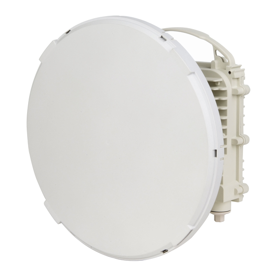
- Page 18 ODU + antenna (31 cm): 4 kg Weight ODU + antenna (31 cm): 3.5 kg Functional Description Licensing Management Error! Reference source not found. Figure 1-1 EtherHaul 1200 System EH-INST-03, Issue 1.0 Page 18...
-
Page 19: System Applications
As a bonus, licensing registration processes for this band are cheaper, simpler, and quicker. With 1 Gbps throughput, the EtherHaul 1200 radio future-proofs the backhaul network to meet the growth in demand for data capacity from 4G, LTE, and WiMAX installations. -
Page 20: Main Features
“pay as you grow” basis. Supporting point-to-point, daisy-chain, ring, and mesh configurations, the EtherHaul system offers carrier class availability and services. The following are some of the main features of the EtherHaul 1200 (availability of features depends on platform): All-Outdoor Packet E-band Radio EH-INST-03, Issue 1.0... - Page 21 Installation and User Manual Operates in the licensed 71-76/81-86 GHz E-band Up to 1 Gbps throughput Asymmetric capacity configuration [1200/TL] High gain narrow beam-width directional antenna Low latency Highest Spectral Efficiency in E-band Spectrum 250 MHz, 500 MHz channel bandwidth ...
- Page 22 Installation and User Manual Advanced AES encryption and security Narrow and secure beam-width EH-INST-03, Issue 1.0 Page 22...
-
Page 23: Eh1200 Product Family
Installation and User Manual EH1200 Product Family Feature EH1200 EH1200TL EH1200F EH1200FL Frequency 71-76 GHz 71-76/81-86 GHz Duplexing Modulation QPSK/QAM16/QAM64 QPSK/QAM16 QPSK/QAM16/QAM64 QPSK/QAM16 Schemes- ABCM Up to 1000Mbps 700Mbps Up to 1000Mbps 7000Mbps System throughput half-duplex half-duplex full-duplex full-duplex 4xGE - 2xCopper+ 2xFiber ports Traffic Interfaces 2 x GE –... -
Page 24: Functional Description
ODU + antenna (31 cm): 4 kg Weight ODU + antenna (31 cm): 3.5 kg Functional Description The EtherHaul 1200 system consists of an outdoor unit (radio link unit and antenna). Figure 1-4 EtherHaul 1200/1200TL Functional Block Diagram EH-INST-03, Issue 1.0 Page 24... -
Page 25: Licensing
Antenna – Siklu’s self-designed, innovative antenna is designed for best price- performance ratio. Licensing The EtherHaul 1200 provides for easy migration to support Gigabit throughput, enabling operators to enhance bandwidth capacity on a “pay as you grow” basis as well as adding EH-INST-02, Issue 5.0... -
Page 26: Management
The software licenses are serial number dependent. Management You can manage an EtherHaul 1200 system using a Web-Based Element Management System (Web EMS) or a Command Line Interface (CLI). The CLI is compatible with SNMP. Advanced network features must be managed using the CLI. -
Page 27: Installing The Etherhaul 1200
Performing Initial System Setup Note: The installation and maintenance of the EtherHaul 1200 link should only be done by service personnel who are properly trained and certified to carry out such activities. Preparing the Site Carefully select and prepare each EtherHaul ODU site to make device installation and configuration as simple and trouble-free as possible. -
Page 28: Cabling Requirements
Improper electrical grounding can result in excessive electromagnetic interference or electrical discharge. Note: Siklu will not be held responsible for any malfunction or damage in the event that the ODU is not properly grounded. EtherHaul 1200 Package Contents An EtherHaul 1200 link consists of two ODUs and two mounting assemblies. -
Page 29: Unpacking The Etherhaul 1200
EtherHaul distributor before attempting to install the equipment. Unpacking the EtherHaul 1200 When you unpack the components of the EtherHaul 1200, it is important to use care so as to avoid damaging or scratching the antenna radome: ... - Page 30 Installation and User Manual Calculating the expected RSSI: RSSI = P – LFS – Att + Gant2 ant1 Where: – ODU’s Tx Power (typically +5dBm) Gant1 – Gain of antenna 1 (in dBi) Gant2 – Gain of antenna 2 (in dBi) ...
-
Page 31: Mounting The Etherhaul 1200
These instructions are for mounting a system with a one-foot antenna. For Note: instructions on mounting the EtherHaul 1200 with a two-foot antenna, refer to Appendix A: Install the ODU with Two Foot Antenna. Torque level for tighten the nuts/bolts is 8nm. - Page 32 Installation and User Manual 5. Use the 13mm open wrench to tighten the nuts on both Unit Mounting Bolts. Temporarily tighten the Unit Mounting Bolts at this stage to keep the unit from moving freely. 6. By default, the ODU is delivered with the Quick Release Plate () securely attached in a vertical polarization.
-
Page 33: Connecting The Cables
4. Ethernet Cable RJ45 Interface 9, Reset Button (press for more than 5 seconds to restore factory defaults) 5. Fiber Cable SFP Interface Figure 2-2 EtherHaul 1200 Connection Panel Details Figure 2-3 EtherHaul 1200 DC Power Connector Pin-Out Diagram EH-INST-02, Issue 5.0... -
Page 34: Grounding The Etherhaul 1200
Installation and User Manual 2.7.1 Grounding the EtherHaul 1200 The location of the Electrical Ground Outlet on the ODU is shown in Figure 2-2. 1. Connect one end of the Grounding Cable to the Ground Outlet on the left side of the ODU using the Grounding Cable Lug. -
Page 35: Preparing The Cables
The DC input is floating, so either (+) or (-) can be connected to the GND on the power supply side. For the sake of consistency with other systems, Siklu recommends that you connect the (+) to the GND. -
Page 36: Removing Connectors From The Etherhaul Odu
Installation and User Manual 3 sets of Rubber Gasket Insert are provided for different cable diameters: 4.2mm inner diameter – for cable diameter 3.5-4.9mm 5.8mm inner diameter – for cable diameter 5.0-6.7mm 7.9mm inner diameter – for cable diameter 6.8-9.0mm 1. -
Page 37: Connecting The Power
Installation and User Manual 2. Unscrew the Connector Outlet Portion () of the All-Weather Shell from its ODU port. 3. Remove the cable connector from its port. 2.7.5 Connecting the Power 1. Carefully screw the Connector Outlet Portion ( ) of the All-Weather Shell into the PWR port or alternatively, if a PoE connection is being used, the RJ1 port. -
Page 38: Setting The Odu To Alignment Mode
Appendix A: Install the ODU with Two Foot Antenna. Note: These instructions refer to Figure 2-1 EtherHaul 1200 Mounting Assembly Components 1. Verify that the ODU is in Alignment Mode. Refer to Aligning the Antenna on page 37. - Page 39 Installation and User Manual Fine Alignment When aligning an antenna, the antenna in the remote node must remain completely stationary. Fine alignment is performed first on the local antenna, and only Note: afterwards on the remote antenna. The optimum alignment may require several adjustment iterations between the local and remote antennas.
-
Page 40: Performing Initial System Setup
3. Carefully reinsert and tighten using the 13mm open wrench the AUX port protective seal. The EtherHaul 1200 link can now pass traffic and management between the ports and over the radio link. Further configuration can be performed using the Web EMS or the CLI. - Page 41 Installation and User Manual Note: To perform configuration and monitoring, you must connect your laptop or PC to one of the two Ethernet ports on the ODU. EH-INST-02, Issue 5.0...
-
Page 42: Performing Basic Configuration Using The Web Ems
Installation and User Manual Performing Basic Configuration Using the Web EMS This chapter explains how to perform basic configuration tasks using the Web EMS. For instructions how to configure a link using the CLI, refer to Performing Basic Configuration using the CLI on page 55. ... -
Page 43: Connecting To The Odu Using The Web Ems
Installation and User Manual Connecting to the ODU Using the Web EMS 1. Launch an Internet browser and enter the ODU’s IP address in the address bar. The default IP address is https://192.168.0.1. 2. Wait for the Java Applet to load and enter the username and password (admin, admin). -
Page 44: Saving Configuration Changes And Resetting The System Using The Web Ems
Installation and User Manual Figure 3-2 Web EMS Main Screen (1200FL/1200F) Saving Configuration Changes and Resetting the System Using the Web EMS Whenever you make changes to the ODU configuration using the Web EMS, you must click Save Configuration on the Web EMS Main screen in order to save the configuration changes to the startup configuration. -
Page 45: Configuring And Displaying Basic System Information Using The Web Ems
Installation and User Manual Configuring and Displaying Basic System Information Using the Web EMS You can view and configure basic system information in the System Information section of the Quick Configuration screen. Figure 3-45 Web EMS Quick Configuration Screen – System Information Section The following are the basic system parameters: ... -
Page 46: Configuring System Ip Addresses Using The Web Ems
Installation and User Manual Voltage (and indication about power source: DC or PoE) Configuring System IP Addresses Using the Web EMS You can change and add system IP addresses in the IP section of the Quick Configuration screen, or by clicking System on the Web EMS Main screen and clicking the IP section of the System screen. -
Page 47: Figure 3-6 Add Route Window
Installation and User Manual 2. In the Index field, select the index of the IP you want to add or change. Select Index #1 if a single IP is used and you wish to change it. Note: If you change the default IP address, your connection to the ODU will be lost. To re- establish a connection, launch an Internet browser and connect using the new IP address. -
Page 48: Configuring Radio Parameters Using The Web Ems
Installation and User Manual Index – 1 IP Address – Static 192.168.0.17 Prefix Lenght – 24 VLAN – 0 ODU config – Static Route screen: Index – 1 Destination – 0.0.0.0 Prefix Length – 0 ... -
Page 49: Figure 3 -8 Web Ems System Screen - Radio Section (1200F/1200Fl)
Installation and User Manual Figure 3-8 Web EMS System Screen – Radio Section (1200F/1200FL) Tx Frequency (MHz) – Select a frequency channel (on 1200F/1200FL systems, the Rx Frequency will be updated automatically). The default values is 74375/84375. Channel Width (MHz) – 250MHz or 500MHz. Default value is 500. ... - Page 50 Installation and User Manual Note: Max modulation for 1200TL/1200FL systems is 16QAM Sub Channels – From 1 to 4 (occupied bandwidth. For Channel Width 500MHz: 125-500MHz) Repetitions – 1,2 or 4 FEC Rate – 0.5 When using the system in Static mode, you must select from a pre-defined list of modulation profiles.
-
Page 51: Viewing Modulation Profiles Using The Web Ems
Installation and User Manual Viewing Modulation Profiles Using the Web EMS To view the available modulation profiles, click Radio on the Web EMS Main screen and click the Modulations section of the Radio screen. Note that different modulation tables may apply according to product and according to the frequency channel used. -
Page 52: Figure 3-11 Interface Icons On Web Ems Main Screen
Installation and User Manual Figure 3-11 Interface Icons on Web EMS Main Screen Figure 3-12 Interface Screen Admin Status – Determines whether the port is enabled (up) or disabled (down). Default value is up. Oper. Status – Displays the operational status of the port - up or down. ... -
Page 53: Configuring Snmp Settings
Installation and User Manual Ethernet Type – When Auto Negotiation is disabled, select the port’s speed manually in this field (10/100/1000, HF/FD). When using the SFP physical port, set this field to 1000xfd. Default value for the Electrical RJ45 ports is 1000fd (1000 Full-Duplex). -
Page 54: Default Vlan Setting
Installation and User Manual You can define up to five managers, with the following settings: Destination IP Address UDP Port Number Security Name (community) Figure 3-13 Web EMS System Screen – SNMP Managers Section To add or change managers, click Add. When you are finished, click Apply. -
Page 55: Performing Basic Configuration Using The Cli
Installation and User Manual Performing Basic Configuration using the CLI This chapter explains how to perform basic configuration tasks using the CLI. For instructions how to configure a link using the Web EMS, refer to Performing Basic Configuration Using the Web EMS on page 42. ... -
Page 56: Saving Configuration Changes And Resetting The System Using The Cli
Installation and User Manual Saving Configuration Changes and Resetting the System Using the CLI Whenever you make changes to the ODU configuration, you must save the configuration changes to the startup configuration. If you do not save the configuration, the changes will be lost the next time the system is reset. -
Page 57: Configuring System Ip Addresses Using The Cli
Installation and User Manual Configuring System IP Addresses Using the CLI The EtherHaul ODU supports up to four IP addresses that can be on different subnets and associated with different VLANs. You can assign a static route to each IP address. The Default IP-Gateway is defined as a static route. - Page 58 Installation and User Manual For example: 1200/1200F/1200FL Systems Local_Site>show ip ip 1 ip-addr : static 192.168.0.11 ip 1 prefix-len : 24 ip 1 vlan ip 1 default-gateway : 192.168.0.254 To delete IP entries, use the clear ip command: clear ip <index> To create and modify an IP Route and Default Gateway, use the set route command:...
-
Page 59: Configuring Radio Parameters Using The Cli
Installation and User Manual Configuring Radio Parameters Using the CLI This section lists and describes the CLI commands you need to configure and display radio parameters. Use the set rf command, followed by the name of the parameter you want to configure, to configure the ODU’s radio parameters: For example: Local_Site>set rf tx-power 3... -
Page 60: Configuring The Radio Parameters Using The Cli
Installation and User Manual For example: 1200/1200F/1200FL Systems Local Site>show rf rf operational : up rf tx-state : normal rf rx-state : normal rf cinr : 24 rf rssi : -42 rf channel-width : 500 rf tx-frequency : 72375 rf rx-frequency : 82375 rf role : auto... -
Page 61: Viewing Modulation Profiles Using The Cli
Installation and User Manual [lowest-modulation {<modulation> <subchannels> <repetitions> <fec-rate> - (from list of modulations)}] [tx-asymmetry (for 1200T/1200TL systems) for master use 50tx-50rx, 75tx-25rx, 90tx-10rx for slave use 50tx-50rx, 25tx-75rx, 10tx-90rx}] [tx-link-id <integer 0..127>] [rx-link-id <integer 0..127>] [loopback {internal-mac-swap <modulation> <subchannels> <repetitions> <fec-rate> - (from list of modulations) | disabled}] [loopback-timeout <integer 0..86400>] [tx-power <integer -35..5>]... -
Page 62: Configuring Ethernet Interfaces Using The Cli
Installation and User Manual Configuring Ethernet Interfaces Using the CLI The EtherHaul system has four Ethernet interfaces: Host – Management interface Eth0 – Radio interface Eth1 – ODU interface, port 1 Eth2 – ODU interface, port 2 ... -
Page 63: Default Vlan Setting
Installation and User Manual | alarm-propagation}]] The following is an example of an Ethernet interface status display. Local_Site> show eth eth1 eth eth1 description : Siklu eth eth1 mtu : 9216 eth eth1 mac-addr : 00:24:a4:00:06:d2 eth eth1 admin : up... -
Page 64: Commissioning And Acceptance Procedure
RF link commissioning and acceptance. 5.1.1 Physical Installation Verification This inspection verifies the physical installation of the ODU, in accordance with Installing the EtherHaul 1200 on page 27. Pole mount installation ... -
Page 65: Link Errors Test
Installation and User Manual Receive Signal Strength Indication (RSSI) achieved in Alignment Mode is within +/-5dB of the expected value Carrier to Interference + Noise Ratio (CINR) is 17 or higher Link configuration (modulation, mode) is in accordance with plan requirements 5.1.3 Link Errors Test... -
Page 66: Etherhaul Commissioning And Acceptance Form
Mount type Roof-top Roof-top Mast/Tower Mast/Tower ODU mount above ground meters meters Clear line-of-sight ODU safely mounted using Siklu’s bracket correctly installed Pole diameter between 2-4” Bracket’s mounting bolts securely tightened ODU grounding Cables/Fibers Connections Eth1 Cat5 Eth1 Fiber Eth1 Cat5... - Page 67 Installation and User Manual Cables/Fibers are properly weatherproofed using the appropriate glands ODU DC source External DC External DC PoE model and manufacturer Measured DC power (or CLI/Web Volts DC Volts DC reading) RF Link Parameters ODU Model ODU P/N ODU S/N ODU running SW version Tx/Rx Frequency...
- Page 68 Installation and User Manual Measured RSSI Measured CINR Green “RF” led RF operational status Up RF Statistics error counters clear Ethernet Services Tests Packet-Loss test No Packet-Loss No Packet-Loss Packet Analyzer SW-based Test duration __________ Test duration __________ Eth Statistics dropped-packets counters clear Management IP address/Mask...
- Page 69 Installation and User Manual Additional Info / Remarks I&C Details I&C Date Installation team Commissioning team EH-INST-02, Issue 5.0...
-
Page 70: Etherhaul Networking Configuration
Installation and User Manual EtherHaul Networking Configuration This chapter presents the EtherHaul bridge management model and describes the initial procedures for configuring the EtherHaul network, including: Provider Bridge EH-INST-03, Issue 1.0 Page 70... -
Page 71: Provider Bridge
S-VLAN tag only, while the C-VLAN tag remains shielded during data transmission. The S-VLAN tag is removed when the frame exits the provider network, restoring the original customer frame. The EtherHaul 1200 incorporates a fully functional integrated Provider Bridge (IEEE 802.1ad). EH-INST-02, Issue 5.0... -
Page 72: Etherhaul Bridging Model
Installation and User Manual EtherHaul Bridging Model The Siklu implementation of Provider Bridge is a network of up to seven virtual bridges connected in a “cross-like” fashion as shown in Figure 6-1 and Figure 6-2. Figure 6-1 EH1200/1200TL Generic Model of the EtherHaul Bridge Figure 6-2 EH1200F/1200FL Generic Model of the EtherHaul Bridge Each component acts as a virtual bridge. -
Page 73: Configuring Vlans
Installation and User Manual You can change the default bridge configuration to suit your network by removing or adding the desired bridge components. All components are created, managed, and removed using the CLI or Web EMS. Configuring VLANs This section lists the default VLAN and Port settings, and provides instructions how to modify these settings. -
Page 74: Configuring Vlans Using The Web Ems
Installation and User Manual default>show vlan component-id fdb-id egress untagged history c1,c2,c3,c4 c1,c2,c3,c4 disable undef c1,c2,c3,c4 none disable host,s1 host disable undef host,s1 none disable eth0,s1 eth0 disable undef eth0,s1 none disable eth1,s1 eth1 disable undef eth1,s1 none disable eth2,s1 eth2 disable undef... -
Page 75: Figure 6 -3 Add Vlan Window
Installation and User Manual 2. Click Add. The Add VLAN window is displayed. Figure 6-5 Add VLAN Window 3. Configure the following VLAN attributes for the required components: - VID – C-VLAN Identifier. This can be any number from 1 to 4094, which identifies a particular C-VLAN, or the special value “undef”, which identifies configuration relevant for all VLANs that are not explicitly defined in the VLAN Table. -
Page 76: Configuring Vlans Using The Cli
Installation and User Manual 6.3.3 Configuring VLANs Using the CLI 6.3.3.1 Creating and Modifying VLANs VLAN definitions are stored in a table containing static configuration information for each VLAN that is configured in the device by local or network management. All VLAN Table entries are permanent and are restored when the device is reset. - Page 77 Installation and User Manual 6.3.3.3 Deleting VLANs Use the clear vlan command to delete VLANs and clear their associated statistics. Use the following syntax: clear vlan {<comp-id-list> | all} {<vid-list> | all} [statistics] 6.3.3.4 Displaying VLAN Details Use the show vlan command to display VLANs and their details.
-
Page 78: Configuring Bridge Ports
Installation and User Manual Configuring Bridge Ports 6.4.1 Configuring Bridge Ports Using the Web EMS To configure ports using the Web EMS: 1. In the Web EMS Main screen, click Bridge. The Bridge screen is displayed. 2. Click the Bridge Ports section of the Bridge Ports screen. Figure 6-6 Web EMS Bridge Screen –... -
Page 79: Configuring Bridge Ports Using The Cli
Installation and User Manual 5. Configure the following Port attributes: pvid A vid which will be assigned to an untagged frame or a priority-tagged frame, but VID is set to 0 indicating that the frame does not belong to any VLAN and only PCP field is relevant), which enters to the bridge through this port. -
Page 80: Configuring The Bridging Port
Installation and User Manual 6.4.3 Configuring the Bridging Port The bridging port provides access to port-wide definitions from the bridge. When using bridge-port commands, you can specify any combination of components and ports. However, only certain combinations will produce a result. In the current product version, the following usage restrictions exist: ... -
Page 81: Configuring Provider Bridge And Advanced Vlan Settings
Installation and User Manual Configuring Provider Bridge and Advanced VLAN Settings 6.5.1 Configuring PEP Virtual Ports PEP Virtual Ports are used to configure ingress port filtering. PEP table entries define traffic flows from the provider network to the customer edge port. The table is indexed by Component ID and S-VID. -
Page 82: S-Vid Translation Table
Installation and User Manual 6.5.2 S-VID Translation Table The S-VID Translation table is used to maintain bi-directional mapping between a Local S-VID (used in data and protocol frames transmitted and received through a CNP or PNP) and a Relay S-VID (used by the filtering and forwarding process). Each VID Translation Table definition contains Component, Port, Local S-VID values and the Relay S-VID values for each specified S-VID. -
Page 83: C-Vlan Registration Table
Installation and User Manual 6.5.3 C-VLAN Registration Table An element of the C-VID registration table is accessed by PB C-VLAN component, Customer Edge Port bridge port number, and C-VID. Each element contains the mapping between a C-VID and the S-VID which carries the service and Booleans for handling untagged frames at the PEP and CEP. -
Page 84: Forwarding Data Base (Fdb)
Installation and User Manual 6.5.5 Forwarding Data Base (FDB) The Forwarding Data Base (FDB) enables access to general parameters of the FDB Address table, which specifies configuration and control information for each Filtering Database currently operating on the device. The system maintains 64 permanent instances of the FDB object. Use the following command to create and modify FDB entries: set fdb s1 <fdb-id-list>... -
Page 85: Fdb Address Table
Installation and User Manual The Bridge Common option allows you to configure default CVlan EtherType when handling S-Vlan frames. Figure 6-9 Web EMS Bridge Common EtherType configuration using the CLI: CLI>set bridge c4 vlan-ethertype ? hex number 0x700..0xFFFF except 0x800, 0x806, 0x8809, 0x88CC, 0x8902 Example of setting C4 with Eth-Type of 0x8111: CLI>set bridge c4 vlan-ethertype 0x8111... - Page 86 Installation and User Manual Note that the set fdb-table command fails if its port already exists in the FDB with self as the assigned status. Use the following command to display FDB Address table entries: show fdb-table [{s1 | all} [{<fdb-id-list>...
-
Page 87: Performing Advanced Configuration
Installation and User Manual Performing Advanced Configuration Configuring Quality-of-Service Quality of Service (QoS) mechanisms enable service providers to offer different classes of service for different types of traffic or customers. QoS mechanisms are especially important in wireless links with adaptive capabilities, because changing link conditions may require the system to drop some traffic according to a predetermined priority and scheduling scheme. -
Page 88: Qos Classification
7.1.1 QoS Classification The EtherHaul 1200 QoS Engine classifies the incoming packets by port, VID, PCP, and/or DSCP (as defined by the IEEE 802.1 Q/p and RFC-2475 standards), or alternatively MPLS EXP bit and maps them onto {EVC, CoS} pairs. - Page 89 Installation and User Manual Classifier-Cos settings example for management priority (for traffic from ports: Host, Eth2): set classifier-cos 1 interface host precedence 1 vid 0-4094 pcp 0- 7 ip-cos dont-care cos 7 set classifier-cos 2 interface eth2 precedence 1 vid 0-4094 pcp 0- 7 ip-cos dont-care cos 7 Classifier-Cos settings example for priority based on PCP (pBits) on Eth1, Eth0 with management priority (for traffic from ports: Host, Eth2):...
-
Page 90: Figure 7-2 Classifier-Cos Setup
Installation and User Manual Figure 7-2 Classifier-COS Setup 7.1.1.2 Classifier-EVC Settings Use the following command to configure classifier-evc: set classifier-evc <classifier-id: 1..248> [interface <host|eth0| eth1|eth2>] [precedence <1..8>] [vid < list 0..4094>] [pcp < list 0..7>] [ip-cos <{{dscp-cos | mpls-exp} <list of 0..7>}|dont-care>] [evc <1..31>] Classifier-EVC settings for priority based on PCP (pBits) on Eth0 and Eth1: # classifier-evc configuring... -
Page 91: Metering And Coloring
Installation and User Manual set classifier-evc 7 interface eth0 precedence 1 vid 0-4094 pcp 6 ip-cos dont-care evc 7 set classifier-evc 8 interface eth0 precedence 1 vid 0-4094 pcp 7 ip-cos dont-care evc 8 Figure 7-3 Classifier-EVC Setup 7.1.2 Metering and Coloring 7.1.2.1 Configuring Meter This is an optional mechanism (only for use in cases in which classifier-evc is configured) -
Page 92: Qos Scheduling
The following is an example of binding the meter (configured above) to an evc and cos: # ingress-qos configuring set ingress-qos 5 5 meter 1 marking enable Figure 7-5 Ingress-COS Setup 7.1.3 QoS Scheduling The EtherHaul 1200 QoS mechanism operates according to the following scheduling mechanisms: EH-INST-03, Issue 1.0 Page 92... -
Page 93: Figure 7-6 Scheduling Mechanisms
Installation and User Manual Figure 7-6 Scheduling Mechanisms Strict Priority - Lower priority packets are served only if all higher priority queues are empty. Weighted Fair Queuing (WFQ) – Weights can be assigned to the radio queues, assuring fairness between the queues. ... -
Page 94: Figure 7-7 Wfq/Shaper Setup
Installation and User Manual Error! Reference source not found. provides an example of WFQ. Radio Rate Mbps # Queue Weight Expected Rate Stream rate = SP CoS 7 Stream rate = SP CoS 6 Stream rate = WFQ CoS 5 76.2 Stream rate = WFQ CoS 4... - Page 95 Installation and User Manual 7.1.3.2 Shaper Shaper is used to control traffic flows in order to optimize or guarantee performance and improve latency by limiting the maximum bandwidth of certain flows to maintain fairness and to assure SLA. You must set the Committed Information Rate to a value between 1-1000 Mbps. Error! Reference source not found.
- Page 96 Installation and User Manual 7.1.3.3 Egress Queues There are eight egress queues, one queue per CoS. Eight queues for each of the interfaces (Eth0, Eth1, Eth2, Eth3, Eth4) are served by four queues on the radio (RF). WFQ and Shaper can only be configured for queues 1 through 5. EH-INST-03, Issue 1.0 Page 96...
-
Page 97: Configuring Cfm (Connectivity Fault Management)
Installation and User Manual Configuring CFM (Connectivity Fault Management) This section explains how to configure CFM, and includes the following topics: CFM Overview Working with Maintenance Domains Working with Maintenance Associations Working with Component Maintenance Associations ... -
Page 98: Cfm Overview
Installation and User Manual 7.2.1 CFM Overview Connectivity Fault Management (CFM) is an Ethernet layer operation, administration, and management (OAM) protocol designed to monitor and troubleshoot networks. CFM enables you to detect, verify, and isolate connectivity failures in virtual bridged local area networks. -
Page 99: Working With Maintenance Domains
Installation and User Manual 7.2.1.4 Fault Notification and Recovery When an MEP detects a connectivity fault in its in its MA (CCM is not received or an invalid CCM is received), it sends an SNMP trap and enters a log entry. The network administrator responds to a fault notification to categorizing, isolating, and resolving the connectivity fault. -
Page 100: Working With Maintenance Associations
Installation and User Manual 7.2.3 Working with Maintenance Associations A Maintenance Association (MA) is used to monitor connectivity in relation to a specific service instance. All CFM entities that support that service instance are configured as MEPs, with the same Maintenance Association Identifier (MAID) and MD Level. ma-name Use the following command to set an MA. -
Page 101: Working With Maintenance End Points (Meps)
Installation and User Manual Figure 7-11 CFM MA Setup 7.2.5 Working with Maintenance End Points (MEPS) A Maintenance End Point (MEP) is a point, on the perimeter of a domain, which sends and receives CFM frames through the domain. Use the following command to set an MEP: set cfm-mep <md-idx>... -
Page 102: Figure 7 -11 Cfm Mep Setup
Installation and User Manual Figure 7-12 CFM MEP Setup EH-INST-03, Issue 1.0 Page 102... -
Page 103: Working With Peer Meps
Installation and User Manual 7.2.6 Working with Peer MEPs MEPs connected by the EtherHaul Provider Bridge feature are known as Peer MEPs. Peer MEPs can be used to measure CCM delay and changes in that delay. Use the following command to create a Peer MEP entry. This command causes automatic creation of entries in the Peer MEP DB for all MEPIDs that have entries in MEP table and this Peer MEP ID. -
Page 104: Working With Ccm Messages
Installation and User Manual 7.2.7 Working with CCM Messages An MEP can periodically transmit a multicast Connectivity Check Message (CCM) announcing the identity of the MEP and its MA. The MEP also tracks CCMs received from the other MEPs. The following information is displayed per CCM message stored: ... -
Page 105: Working With Linktrace Messages
Installation and User Manual 7.2.8 Working with Linktrace Messages Linktrace messages are multicast from an originating MEP to a target MAC (MIP or MEP)/MEP ID, to verify the path between the two. Linktrace Reply messages (LTRs) are unicast from the target (or MIPs on route) to the originating MEP. Receipt of an LTR verifies the path. -
Page 106: Sample Cfm Configuration
Installation and User Manual Figure 7-15 Link Trace Status 7.2.9 Sample CFM Configuration This section provides a sample CFM configuration script. Configuring the Local ODU The first step in configuring CFM parameters is to enable the OAM license, which is part of the L2 Networking license. - Page 107 Installation and User Manual The following command creates a Maintenance End Point (MEP). set cfm-mep 2 2 1 interface eth1 dir up cci enabled The following command creates a Peer MEP. set cfm-peer-mep-create 2 2 2 The following command sets the MIP to the lower level. set cfm-ma-comp c3 2 2 vlan 200 mhf-creation explicit To create MIPs on the radio potr (lower level), you must create the Component MA on C3 (Up MEP).
- Page 108 Installation and User Manual set cfm-ma-comp c3 2 2 vlan 200 The following command creates a Maintenance End Point (MEP). set cfm-mep 2 2 2 interface eth1 dir up cci enabled The following command creates a Peer MEP. set cfm-peer-mep-create 2 2 1 The following command sets the MIP to the lower level.
- Page 109 Installation and User Manual set cfm-mep 2 2 1 lbm-dst-mepid 2 set cfm-mep 2 2 1 lbm-tx-num 10 set cfm-mep 2 2 1 lbm-tx-status tx-pending To view the loopback reply, you must first verify the number for lbr-in-order . You can then transmit the loopback packets, using the following command: set cfm-mep 1 1 1 lbm-tx-status tx-pending Re-check the number for...
- Page 110 Installation and User Manual cfm-mep 1 1 1 ltm-tx-result : unknown cfm-mep 1 1 1 ltm-tx-sn cfm-mep 1 1 1 lm : disabled cfm-mep 1 1 1 lm-interval : 10s cfm-mep 1 1 1 dm : disabled cfm-mep 1 1 1 dm-interval : 10s cfm-mep 1 1 1 ais-generate : disabled...
- Page 111 Installation and User Manual cfm-mep 2 2 1 ltm-next-sn cfm-mep 2 2 1 ltr-unexpected cfm-mep 2 2 1 ltm-tx-result : unknown cfm-mep 2 2 1 ltm-tx-sn cfm-mep 2 2 1 lm : disabled cfm-mep 2 2 1 lm-interval : 10s cfm-mep 2 2 1 dm : disabled cfm-mep 2 2 1 dm-interval...
- Page 112 Installation and User Manual set cfm-mep 2 2 1 ltm-dst-mepid 2 set cfm-mep 2 2 1 ltm-tx-status tx-pending show cfm-mep 2 2 1 ltr cfm-mep 2 2 1 0 0 rx-ttl : 63 cfm-mep 2 2 1 0 0 ltr-forward : unknown cfm-mep 2 2 1 0 0 relay-action : fdb...
- Page 113 Installation and User Manual cfm-mep 2 2 1 0 2 trm-mep : unknown cfm-mep 2 2 1 0 2 last-egr-id : 00-00-00-24-a4-00-07-aa cfm-mep 2 2 1 0 2 next-egr-id : 00-00-00-00-00-00-00-00 EH-INST-02, Issue 5.0...
-
Page 114: Configuring Link Oam
Installation and User Manual Configuring Link OAM This section explains how to configure Link OAM. Link OAM, as defined in IEEE802.3ah, is an Ethernet layer operation, administration, and management (OAM) protocol designed to monitor and troubleshoot networks. Link OAM enables you to detect, verify, and isolate connectivity failures in point-to-point connections. -
Page 115: Link Oam Discovery
Installation and User Manual link-oam eth2 revision link-oam eth2 functions : loopback 7.3.2 Link OAM Discovery Once enabled, the Link OAM will perform discovery of the peer Ethernet port. To view the discovered peer port (MAC address and other settings): default>show link-oam-peer eth0 link-oam-peer eth0 mac-addr : 00:24:a4:00:1f:b8... - Page 116 Installation and User Manual Use reset loopback command to stop the loopback and return to status: none; default >reset link-oam-loopback eth0 default >show link-oam-loopback eth0 link-oam-loopback eth0 status : none link-oam-loopback eth0 peer-request : process EH-INST-03, Issue 1.0 Page 116...
-
Page 117: Configuring Synchronous Ethernet (Synce)
Synchronization Message Channel (ESMC). ESMC is similar to SSM (Synchronization Status Message), used in Sonnet/SDH systems. ESMC carries information about the Quality Level (ql) and sync status of the source clock, enabling the EtherHaul 1200 to determine which clock source of use-based on performance and the need to avoid loops. -
Page 118: Synce Configuration
Installation and User Manual Quality Levels (ql) names: Name Name ql-stu ql-ssu-b ql-prs ql-inv9 ql-prc ql-eec2 ql-inv3 ql-eec1 ql-ssu-a ql-smc ql-inv5 ql-st3e ql-inv6 ql-prov ql-st2 ql-dnu 7.4.2 SyncE Configuration SyncE is a licensed feature that requires a license for operation. Before configuring SyncE, verify that the SyncE license key is available and enable the license. -
Page 119: Figure 7 -15 Synce Setup Screen
Installation and User Manual ref-clock host ql-config : 11 ref-clock host ql-mode : disable ref-clock host ssm-cvid : none where: status – active | backup 1/2/3 | down ql-actual – The current ql of the active interface. ql-config –... -
Page 120: Typical Synce Scenario
Typical SyncE Scenario Figure 7-18 illustrates a typical SyncE Scenario in which: The local EtherHaul 1200 receives timing information on Eth1 from PRC (ql 2), and distributes it to all interfaces. The remote EtherHaul 1200 receives timing information and is locked on PRC, via Eth0 (RF). -
Page 121: Figure 7 -17 Typical Synce Scenario - Holdover Due To Radio Failure
The local EtherHaul 1200 receives timing information on Eth 1 from PRC (ql 2), and distributes it to all interfaces. There is no input on the remote EtherHaul 1200 because the radio link is down. The remote EtherHaul 1200 switches to holdover mode, maintaining the PRC it received previously and distributing it with its own ql (ql 11). - Page 122 Figure 7-20 illustrates a SyncE scenario in which there is a holdover situation due to line failure: Because of the line failure, the local EtherHaul 1200 does not receive timing information from PRC. The local EtherHaul therefore switches to holdover mode, maintains the timing information it received previously over Eth1, and distributes this information with its own ql (ql 11).
-
Page 123: Figure 7 -18 Typical Synce Scenario - Holdover Due To Line Failure
DNU (Do Not use, ql 15) is returned to the source in order to prevent timing loops. Figure 7-20 Typical SyncE Scenario – Holdover Due to Line Failure The configuration for this scenario is: Local EtherHaul 1200 Default>show ref-clock ref-clock host prio : 255... -
Page 124: Synce Alarms
Installation and User Manual ref-clock eth0 ql-actual : 11 ref-clock eth0 ql-config : 14 ref-clock eth0 ql-mode : enable ref-clock eth0 ssm-cvid : none 7.4.4 SyncE Alarms Event Classification Default Severity Destination Reference Clock Event Trap (ref-clock Switch switch), Log Reception of QL Alarm Medium... -
Page 125: Ieee 1588V2 Transparent Clock (Tc)
Installation and User Manual IEEE 1588v2 Transparent Clock (TC) 7.5.1 Implementation Overview In wireless link the compensation of the PDV needs to be done for the entire link including the air interface and not only per node. Siklus TC is based on Vitesse VSC8574 HW stamping and distributed TC algor ithm to synchronize the 2 ends of the link. -
Page 126: Optional Network Topologies
Installation and User Manual 7.5.2 Optional network topologies Figure 7-22 Optional Network Topology Boundary Clocks (BCs) and Transparent Clocks (TCs) can be used to overcome the performance issue due to packet delay variation. The topologies using either BC or T C or mixed together in the network will be determined by the results and the accuracy of the network between the master and the slave devices. - Page 127 Installation and User Manual CLI example: (Activated by Sync-E license) CLI>show eth eth1 ieee1588-ipudp eth eth1 ieee1588-ipudp : off CLI>set eth eth1 ieee1588-ipudp ? on | off CLI>set eth eth1 ieee1588-ipudp on Set done: eth eth1 CLI> EH-INST-02, Issue 5.0...
-
Page 128: Configuring Ethernet Ring Protection (Erp)
ERP support enables protection for any point of failure in the network. This means that network connectivity is maintained in the event that the Ethernet link, the radio link, or even the entire EtherHaul 1200 fails. This provides resiliency for both Ethernet-Ethernet rings that typically protect single site connectivity and Ethernet -RF rings that typically protect against RF network failure. -
Page 129: Erp Ring Commands
Installation and User Manual Ability to block RPL at both ends of the link (RPL owner and RPL neighbor) Multiple logical ERP instances over a given physical ring Link failure detection can be based over CCM's or Physical link down. ... -
Page 130: Erp Administrative Commands
| {<md-idx> <ma-idx> <mep-id> <peer-mep-id>} 7.6.3 ERP Administrative Commands The EtherHaul 1200 provides two commands for blocking a particular ring port: Forced Switch (FS) – Can be used even if there is an existing condition. Multiple FS commands are supported per ring. FS commands can be used to enable immediate maintenance operations. -
Page 131: Erp Timers
Installation and User Manual Set done: ring 3 Right_Master>show log 4 21:43:18 sw cad: local Manual switch at 200 CW unblocked ACW blocked Right_Master>set ring 3 action clear Set done: ring 3 Right_Master>show log 4 21:43:18 sw cad: local Manual switch at 200 CW unblocked ACW blocked 4 21:44:36 sw cad: ERP 200is ready Role acw-rpl 7.6.4... - Page 132 Installation and User Manual ring 1 hold-off-timer ring 1 hold-off-time ring 1 guard-timer : 500 ring 1 guard-timer : 500 ring 1 wtb-timer : 5500 ring 1 wtb-timer : 5500 ring 1 wtr-timer ring 1 wtr-timer ring 1 cw-status-data : unblocked ring 1 cw-status-data : unblocked ring 1 acw-status-data : unblocked...
-
Page 133: Monitoring The System
Installation and User Manual Monitoring the System This chapter explains how to monitor system events, status, and statistics, and includes the following topics: Viewing Active Alarms Viewing Alarm History and System Events Events configuration (masking) Viewing Radio Statistics ... -
Page 134: Viewing Alarm History And System Events
Installation and User Manual Viewing Alarm History and System Events You can display a log of alarms and system events using the Web EMS or the CLI. For a detailed explanation of EtherHaul events and alarms, and instructions on how to use them in diagnosing EtherHaul system problems, refer to EtherHaul Diagnostics on page 171. -
Page 135: Figure 8-3 Events Configuration Screen
Installation and User Manual set event-cfg <event-cfg-id-list> [mask <value>] Use the following command to view the events configuration: CLI>show event-cfg event-cfg link-down mask : no event-cfg temperature-high mask : no event-cfg cfm-fault-alarm mask : no event-cfg synthesizer-unlock mask : no event-cfg poe-status-low mask : no... -
Page 136: Viewing Radio Statistics
Installation and User Manual Viewing Radio Statistics You can display radio statistics using the Web EMS or the CLI. Radio statistic counters can be used to identify radio errors. When there are no errors on In Errored Octets, In Errored Packets, and In Lost Packets in the current radio statistics, this indicates that the radio link is operating without errors. -
Page 137: Viewing A Statistics Summary Using The Web Ems
Installation and User Manual 8.4.2 Viewing a Statistics Summary Using the Web EMS You can display a summary of the ODU’s radio statistics in graph or table format using the Web EMS. To display a summary of the ODU’s radio statistics, click Radio on the Web EMS Main screen and click the Statistics Summary section. -
Page 138: Viewing Radio Statistics Using The Cli
Installation and User Manual 8.4.3 Viewing Radio Statistics Using the CLI Use the show rf statistics command to display radio statistics using the CLI. Statistics are gathered for 96 intervals of 15 minutes (total 24 hours), recording the minimum and maximum values per interval. Local_Site>show rf statistics rf in-octets : 32535265564... -
Page 139: Viewing Radio Statistics Summary Using The Cli
Installation and User Manual 8.4.4 Viewing Radio Statistics Summary Using the CLI Use the show rf statistics-summary command to display a summary of radio statistics using the CLI. Statistics are gathered for 96 intervals of 15 minutes (total 24 hours), recording the minimum and maximum values per interval. Statistics are gathered for 96 intervals of 15 minutes (total 24 hours), recording the minimum and maximum values per interval. -
Page 140: Viewing Queue Statistics
Installation and User Manual Viewing Queue Statistics You can use the CLI to display statistics for outgoing queues and incoming queues. 8.6.1 Viewing Outgoing Queue Statistics Use the following command to display statistics for outgoing queues: show out-queue {{eth0, eth1, eth2,rf} | all} {1..8 | all} statistics Counters of all outgoing queues appear, as follows: Default>>... -
Page 141: Incoming Queues Commands
Installation and User Manual 8.6.2 Incoming Queues Commands Currently Incoming Queues are defined only for rf. However, the design should take into account the possibility that the other interfaces will also have incoming queues and their statistics may be different from rf. Use the following command to display statistics for incoming queues: show in-queue {rf | all} {1..4 | all} statistics Counters of all incoming queues appear, as follows:... -
Page 142: Viewing Ethernet Statistics Using The Cli
Installation and User Manual History – Displays 96 intervals of 15 minutes (total 24 hours) of the statistics counters. To clear the statistic counters, click Clear on the Current tab. 8.7.2 Viewing Ethernet Statistics Using the CLI To display Ethernet statistics using the CLI, use the following command: show eth <eth-list>... - Page 143 Installation and User Manual # start in-octets out-octets in-rate out-rate util 0 2012.12.05 01:01:10 eth0 747984743210 748161700832 1765192 1766392 To display the bandwidth utilization history (last 24 hours in 15 minutes intervals): show eth <eth-list> statistics-summary 0 95 EH-INST-02, Issue 5.0...
-
Page 144: Performing System Administration
Monitoring CLI Sessions Viewing System Inventory Upgrading the License Key Performing Address Translation Siklu File System (SFS) Command Line Scripts Configuring NTP Viewing User Activity Log Managing SNMP EH-INST-03, Issue 1.0... -
Page 145: Configuring Encryption
Installation and User Manual Configuring Encryption The EtherHaul supports 128bit and 256bit AES encryption with Static key. This means that the encryption key (32/64 characters long) must be inserted manually into both ends of the link. If there is an encryption mismatch, traffic will not go over the link. The encryption license must be enabled in order to configure encryption. -
Page 146: Working With Configuration Files
Installation and User Manual Working with Configuration Files The EtherHaul system supports the use of stored network configurations. Generally, a stored configuration is automatically loaded on system startup or following a system reset. 9.2.1 Saving Configurations A stored configuration is created by saving the currently active (running) configuration as the default configuration. -
Page 147: Rollback Operations
Installation and User Manual 9.2.4 Rollback Operations You can roll back system configurations. This is a safety measure to prevent unwanted system changes in the event that a loss of communication occurs while performing configuration activities. The Rollback timeout function reloads the saved startup configuration in the event that no command is entered within a predefined timeout period. -
Page 148: Figure 9-2 Web Ems Advanced Settings Screen - Users Section
Installation and User Manual Figure 9-2 Web EMS Advanced Settings Screen – Users Section 3. Click Add. The Add User window is displayed. Figure 9-3 Web EMS – Add Users Screen 4. In the User Name field, enter the user name. 5. -
Page 149: Upgrading The Odu Software
Installation and User Manual Upgrading the ODU Software The EtherHaul system supports switching in real time between two software versions. EtherHaul maintains an active (running) and a standby software version simultaneously. This enables you to upgrade the software with minimal interruption of service. An external FTP server is required for software download. -
Page 150: Upgrading The Odu Software Using The Web Ems
Installation and User Manual 9.4.1 Upgrading the ODU Software Using the Web EMS To upgrade the ODU software: 1. Connect to the ODU. Refer to Connecting to the ODU Using the Web EMS on page 43. 2. From the Web EMS Main screen, click Advanced Settings and click the Software section of the Advanced Settings screen. -
Page 151: Upgrading The Odu Software Using The Cli
Installation and User Manual 5. Click Apply to download the software. The Software Download window closes, and the software is downloaded to the standby flash bank of the ODU. 6. Once the software has been downloaded, click Run SW in the Software screen. The downloaded software version is activated. -
Page 152: Monitoring Cli Sessions
Installation and User Manual and the standby software version automatically becomes the active software version. 3. If the system reactivates after reset with a software version stored in the standby flash bank, use the accept sw command to make the standby version the active version. -
Page 153: Viewing System Inventory Using The Web Ems
: Chassis inventory 1 hw-rev inventory 1 fw-rev inventory 1 sw-rev inventory 1 serial : F026500011 inventory 1 mfg-name : Siklu inventory 1 model-name : EH-1200-ODU-2ft inventory 1 fru : true 9.6.1 Viewing System Inventory Using the Web EMS To view the ODU’s inventory list using the Web EMS: 1. -
Page 154: Upgrading The License Key
Layer 2 networking capabilities –OAM, Resiliency. Synchronization – Synchronous Ethernet (ITU-T G.8261) Encryption Upgrading a license requires loading (using FTP) a license key that is generated by Siklu based on your EtherHaul 1200 serial number. Default>copy license ://<ftp_user>:<ftp_password>@<FTP server IP address>/<license_file_name> …... -
Page 155: Performing Address Translation
Installation and User Manual Figure 9-10 Advance Setting Screen – License Section (EH1200F) Performing Address Translation The ARP table is used to map between IP addresses and physical addresses. Use the following command to create and modify entries in the ARP table [ip-address <mac-address>] If the ARP entry does not already exist, the set arp... -
Page 156: Siklu File System (Sfs)
Installation and User Manual Table 11-35 on page 250 lists and describes the ARP table attributes. Siklu File System (SFS) 9.9.1 Understanding SFS With SFS, all files can be listed and classified (binary, text file, and so on), including files on remote servers. -
Page 157: File System Commands
Table 9-1 lists and describes the currently supported file storage devices. Table 9-1 Supported Support Devices Device Identification Description FTP server (external server) flash Local flash memory (linux shell /var/siklu/etc). eprom RF module ROM. No directories. /scripts directory resides under flash ( flash:scripts 9.9.3... -
Page 158: Sfs Example For Backup/Restore Of Configuration File
Installation and User Manual 9.9.4 SFS Example for Backup/Restore of Configuration file Backup the configuration file (startup-configuration.txt) to your PC: CLI>copy flash:/startup-configuration.txt ftp://user1:pass@192.168.0.222/backup.txt … finished Restore the Startup-configuration back into the ODU (from the PC): CLI>copy ftp://user1:pass@192.168.0.222/backup.txt flash:/startup- configuration.txt … finished * FTP server address = 192.168.0.222 (Username = user1 // Password = pass) Default>dir flash:... -
Page 159: Displaying Scripts
Installation and User Manual 9.10.1 Displaying Scripts To display scripts using the Web EMS: 1. In the Web EMS Main screen, click Advanced Setup. The Advanced Setup screen is displayed. 2. Click the Scripts section of the Advanced Setup screen. Figure 9-12 Web EMS Advanced Setup Screen –... -
Page 160: Viewing Script Content
Installation and User Manual Figure 9-13 Adding Scripts 9.10.4 Viewing Script Content You cannot display script content directly from the CLI. To view the content of a script, transfer the script to the server and view it with a text editor. In the same manner, you cannot edit scripts directly on the ODU. -
Page 161: Command Line Scripts Using The Cli
The Network Time Protocol (NTP) is a protocol for synchronizing the clocks of network elements over packet-switched, variable-latency data networks. The EtherHaul 1200 supports NTP client. It can synchronize the host clock to any NTP server in the LAN/Internet to deliver accurate and reliable time. -
Page 162: Viewing User Activity Log
Dec 23 08:10:05 sw cad: User: cli admin : set rf tx-mute disable Dec 23 08:12:24 sw cad: User: cli admin : clear log Dec 23 08:16:08 sw cad: User: cli admin : copy sw ftp://192.168.0.254/pub/siklu- uimage-40-5444 Dec 23 08:45:48 sw cad: User: cli tech : run sw immediate no-timeout EH-INST-03, Issue 1.0... -
Page 163: Accss Control List (Acl)
Installation and User Manual Dec 23 09:06:36 sw cad: User: cli admin : copy running-configuration startup- configuration Dec 23 09:13:09 sw cad: User: cli admin : clear log Dec 24 02:36:48 sw cad: User: cli admin : set rf mode alignment Dec 24 02:44:34 sw cad: User: cli admin : set license data-rate status 1000 9.13 Accss Control List (ACL) -
Page 164: Lldp - Link Layer Discovery Protocol
Installation and User Manual access-list 1 cleared CLI> 9.14 LLDP - Link Layer Discovery Protocol The Link Layer Discovery Protocol (LLDP) is a unidirectional neighbor discovery protocol. It enables the EH1200 to discover other network elements that are connected to it. This feature enables, amongst other things, to discovery third-party network elements connected to the EH1200 so that they can be managed. -
Page 165: Figure 9 -16 Web Ems Lldp Window
Installation and User Manual Figure 9-17 Web EMS LLDP Window LLDP configuration using CLI: An example of the remote answer of the LLDP-remote (Eth0 = Over the Radio) CLI>set lldp eth0 admin rx-tx Set done: lldp eth0 CLI>show lldp-remote lldp-remote eth0 0 chassis-id : 192.168.1.152 lldp-remote eth0 0 chassis-id-subtype : network-addr... -
Page 166: Dhcp
Installation and User Manual 9.15 DHCP The Dynamic Host Configuration Protocol (DHCP) is a computer networking protocol used by devices (DHCP clients) to obtain configuration information for operation in an Internet Protocol network. This protocol reduces system administration workload, allowing networks to add devices with little or no manual intervention. DHCP is built on a client-server model, where designated DHCP server hosts allocate network addresses and deliver configuration parameters to dynamically configured hosts. - Page 167 Installation and User Manual CLI>show ip 2 ip 2 ip-addr : dhcp 192.168.0.36 ip 2 prefix-len : 23 ip 2 vlan ip 2 default-gateway : 192.168.1.254 CLI> EH-INST-02, Issue 5.0...
-
Page 168: Managing Snmp
Installation and User Manual 9.16 Managing SNMP The EtherHaul supports SNMPv2 and SNMPv3. SNMP managers and users can be configured. 9.16.1 SNMP Managers The following command sets the SNMP Trap Destination lists: set snmp-mng <ip-addr-list> [udp-port <0..65535>] [security- name <string>] [snmp-version {v2 | v3}] set snmp-mng <1..5>... -
Page 169: Snmp Agent Communities
Installation and User Manual 9.16.2 SNMP Agent Communities The following command sets the SNMP agent communities: set snmp-agent [read-com <value>] [write-com <value>] [snmp-version <value>] Default read-com is “public”. Default write-com is “private”. Default snmp-version is v2. To view the SNMP agent communities: default>show snmp-agent snmp-agent read-com : public... -
Page 170: Figure 9 -19 Web Ems System Screen - Snmp Users Section
Installation and User Manual Figure 9-20 Web EMS System Screen – SNMP Users Section EH-INST-03, Issue 1.0 Page 170... -
Page 171: Etherhaul Diagnostics
Installation and User Manual EtherHaul Diagnostics The EtherHaul system’s highly reliable and easy-to-use radio link features a wide range of built-in indicators and diagnostic tools designed to enable you to quickly evaluate a link’s performance, identify operating faults, and resolve them. The general diagnostics process for an EtherHaul link is to identify whether there is a problem that needs to be addressed, to isolate the root cause of the problem, and to implement the steps that are required to solve the problem. - Page 172 Installation and User Manual Isolate the Fault Further isolate and characterize the problem using all available link indications. Ascertain if the problem is related to: End-equipment configuration or an interconnection A hardware fault in the link’s accessories (such as a cable) ...
-
Page 173: Etherhaul Odu Leds
Installation and User Manual 10.2 EtherHaul ODU LEDs The following table lists the possible status of all LEDs, together with a description for purposes of diagnostics. Color Description PWR (Power) Green – Power OK Blink Green – Device boot Red – Power Failure Off –... -
Page 174: Etherhaul System Alarms And Events
Installation and User Manual 10.3 EtherHaul System Alarms and Events The following table lists all System Alarms and Events, together with their severity, possible cause and corrective actions. Indication Classification Explanation Probable Corrective Actions and Severity Cause The ODU is re-initializing Cold Start Event due to a Power-Up or... - Page 175 Installation and User Manual Classification Probable Indication Explanation Corrective Actions and Severity Cause Link Up Event The communication link (either the RF or one of the Ethernet ports) is [Trap, Log] operational. Modulation Event The modulation setting Change for the RF link (currently in Adaptive mode) has [Trap, Log] changed.
- Page 176 Installation and User Manual Classification Probable Indication Explanation Corrective Actions and Severity Cause Synthesizer Event The synthesizer has been Locked locked. [Trap, Log] Synthesizer The synthesizer has been Alarm Unlocked unlocked. High [Trap, Log, Active Alarm List] The power level being Problematic PoE, 1) Check voltage POE Status Low...
-
Page 177: Etherhaul System Statistics
Installation and User Manual Classification Probable Indication Explanation Corrective Actions and Severity Cause Reception of QL Alarm SyncE quality received on Network changes or the link is same or worse EEC1 or Worse sync failure that the ODU’s internal [Trap, Log, clock quality Active Alarm List]... -
Page 178: Vlan Statistics
Installation and User Manual 10.4.2 VLAN Statistics You can display statistic counters of each EtherHaul component per VLAN: Default>>show vlan all statistics component vlan port in-pkts out-pkts drop-pkts elapsed-time host 0000:00:00:32 host 0000:00:00:32 eth0 0000:00:00:32 eth0 0000:00:00:32 eth0 28601 0000:00:00:32 eth0 28601 0000:00:00:32... -
Page 179: Etherhaul System Loopbacks
10.5.1 Loopback Diagrams 10.5.1.1 System Loopback Points Figure 10-1 EtherHaul 1200 System Loopback Points 10.5.1.2 Ethernet External Line Loopback Point The Ethernet traffic from the customer’s end-equipment or Ethernet analyzer is looped on the Ethernet interface (Eth1 or Eth2), enabling testing of the connection (cable/fiber) and the interface between end-equipment and the ODU. - Page 180 Installation and User Manual When testing a link from one side (local), an external line loopback should be applied on the local unit. The loopback can be applied separately for Eth1 and Eth2, and can be set with or without MAC Address swapping. Set the loopback mode to external for the desired Ethernet port and set the loopback - timeout in seconds: set eth eth1 loopback-timeout 300...
- Page 181 Installation and User Manual Set the loopback mode to internal for the desired Ethernet port and set the loopback - timeout in seconds: set eth eth1 loopback-timeout 300 set eth eth1 loopback-mode internal-mac-swap Use the following command to clear the loopback: set eth eth1 loopback-mode disable EH-INST-02, Issue 5.0...
-
Page 182: Using The Etherhaul Cli
3. Login as user 4. Enter the password admin When a successful connection is established, the ODU responds as follows: Siklu-OS > Default> EtherHaul CLI commands should only be entered at the above prompt. EH-INST-03, Issue 1.0 Page 182... -
Page 183: Cli Command Syntax
Installation and User Manual 11.2 CLI Command Syntax After invoking the CLI, you can input commands. Each CLI command is submitted to the EtherHaul device for execution, after which a response is typically returned. Each command line submitted to the CLI consists of: 1. -
Page 184: Common Syntax Rules
Installation and User Manual 11.2.2 Common Syntax Rules This document uses the following notation conventions when presenting CLI usage examples. These syntax conventions are found in commands, index names, objects and attributes. Syntax Meaning {a | b | c} One of the specified values must be entered in the command line <name>... -
Page 185: Cli Command Types
Installation and User Manual Convention Meaning A comma-separated list of external port names, e.g., host, eth0, eth1, eth2. <ext-bridge-port-list> Any combination of the names can be included in the list. For details, refer to Designating Named Objects on page 189. A list of ranges of VIDs from 1 to 4094. - Page 186 Installation and User Manual Hint: CLI command syntax changes to fit the EtherHaul object being managed or displayed. For specific command syntax and execution details, see the information that accompanies a particular object, starting in CLI Managed Object Reference on page 196.
- Page 187 Installation and User Manual For example: When this Command is entered… …the CLI interprets the Command as: show system show system info. show eth show eth all info. show bridge-port show bridge-port all info show bridge-port c2 show bridge-port c2 all info show bridge-port c2 eth0 show bridge-port c2 eth0 info show vlan...
-
Page 188: Designating Objects In Cli Commands
Installation and User Manual 11.2.4.4 Clear Commands The Clear command is used to reset or delete the specified values for a chosen object. The generic form of the Clear command is: clear object-name <object-ids> [attribute-name] Nearly all clear commands require that at least one object identifier follow the object name in the command line. -
Page 189: Designating Named Objects
Installation and User Manual Object Names Object Indexes 11.2.6 Designating Named Objects Certain EtherHaul CLI objects are identified by symbolic names. These names are static and are always assigned to the same EtherHaul object type. Using static names generally makes system configuration much easier and more consistent from network to network. - Page 190 Installation and User Manual egress host, s1 specifies two egress ports: host and s1. Hint: When using the show and clear commands, the keyword all may be substituted for a list of object names. In this context, “all” means all of the objects. For example: eth all is identical to eth host, eth0, eth1, eth2.
- Page 191 Installation and User Manual vlan 230-270, 300, 401-410 refers to VLANs with the index numbers 230 to 270, VLAN number 300 and VLANs 401 to 410. Designating indexed objects is valid in all show clear commands. If the show command is executed for indexed objects which do not exist, the non-existing objects are ignored and the command is only executed for existing objects.
-
Page 192: Viewing The Cli Command History
Installation and User Manual 11.3 Viewing the CLI Command History The EtherHaul CLI maintains a history of the 100 most recent commands. This is especially useful when recalling long, complex or repetitive entries. To recall commands from the history buffer, you can press the following keys: Key press Result Up Arrow... - Page 193 Installation and User Manual Feature Description Returns a detailed list of commands that begin with a particular character <string> ? string. For example: Default> set vlan? Will return: Default> set vlan <comp-id-list> <vid-list> [fdb-id <fdbid>] [egress <bridge ports>] [untagged <bridge ports>] where <bridge ports>...
-
Page 194: Cli Error Messages
Installation and User Manual 11.5 CLI Error Messages EtherHaul CLI issues three types of error messages: %Ambiguous command. This error occurs when the command entered can only be partially interpreted. If possible, following the error message, a help syntax line is returned to assist you in correcting the command. For example: Default>... -
Page 195: Viewing The Etherhaul Statistics History
Installation and User Manual 11.6 Viewing the EtherHaul Statistics History The EtherHaul CLI enables you to view standard operational and performance statistics for various objects in the system. View the statistics history using the show command: show <object> <comp-id> statistics [{<hist-range>... -
Page 196: Cli Managed Object Reference
Installation and User Manual 11.7 CLI Managed Object Reference This section describes all EtherHaul System objects that can be created, modified, displayed or deleted using the command line interface. Use Figure 11-1 to quickly identify and locate a specific EtherHaul object according to its logical function in the EtherHaul System. -
Page 197: Management Object Attributes
Installation and User Manual 11.8 Management Object Attributes This section lists and describes the attributes of network commands. 11.8.1 System Object Attributes Table 11-1 System Object Attributes Attribute (CLI Description SNMP Object ID Value Access Default Attribute Name) System A text string describing the sysDescr Variable ASCII text EH-1200 HW W.X SW... - Page 198 Installation and User Manual Attribute (CLI Description SNMP Object ID Value Access Default Attribute Name) System Name A name assigned by the sysName Up to 256 characters. "Default" administrator to this (name) (1.3.6.1.2.1.1.5) If no system name managed node. Generally, by exists, the value convention, this is the node's returns a zero-length...
-
Page 199: Physical Inventory Object Attributes
Installation and User Manual 11.8.2 Physical Inventory Object Attributes Table 11-2 Physical Inventory Attributes Attribute (CLI Description SNMP Object ID SNMP Syntax CLI Syntax Attribute Name) entPhysicalIndex integer32 Inventory Index The index for the table entry. integer (1.3.6.1.2.1.47.1.1.1.1.1) (1..2147483647) Physical A textual description of entPhysicalDescr character string... - Page 200 Installation and User Manual Attribute (CLI Description SNMP Object ID SNMP Syntax CLI Syntax Attribute Name) Class (class) An indication of the general entPhysicalClass INTEGER { {other, unknown, hardware type of the physical chassis, backplane, (1.3.6.1.2.1.47.1.1.1.1.5) other(1), entity. If no appropriate container, power- unknown(2), standard registration...
- Page 201 Installation and User Manual Attribute (CLI Description SNMP Object ID SNMP Syntax CLI Syntax Attribute Name) Physical Name The textual name of the entPhysicalName character string character string physical entity. The value of (name) (1.3.6.1.2.1.47.1.1.1.1.7) this object should be the name of the component as assigned by the local device and should be suitable for use in...
- Page 202 Installation and User Manual Attribute (CLI Description SNMP Object ID SNMP Syntax CLI Syntax Attribute Name) Physical The vendor-specific firmware entPhysicalFirmwareRev character string character string Firmware revision string for the physical (1.3.6.1.2.1.47.1.1.1.1.9) Revision (fw-rev) entity. Note that if revision information is stored internally in a non-printable (e.g., binary) format, then the agent must convert such...
- Page 203 Installation and User Manual Attribute (CLI Description SNMP Object ID SNMP Syntax CLI Syntax Attribute Name) Physical Serial The vendor-specific serial entPhysicalSerialNum character string character string (up number string for the physical Number (serial) (1.3.6.1.2.1.47.1.1.1.1.11) (up to 32 chars) to 32 chars) entity.
- Page 204 Installation and User Manual Attribute (CLI Description SNMP Object ID SNMP Syntax CLI Syntax Attribute Name) Field Replaceable This object indicates whether entPhysicalIsFRU {true (1), false(2)} {replaceable | not- Unit Indicator or not this physical entity is (1.3.6.1.2.1.47.1.1.1.1.16) replaceable} (fru) considered a 'field replaceable unit' by the vendor.
-
Page 205: Physical Inventory Entities
RF IC Antenna Modem FPGA CPLD Boot Figure 11-2 Physical Inventory Hierarchy Scheme 11.8.3.1 Overall Product Attribute Value Inventory Index Descriptor “Siklu EH-1200” Contained In Class chassis Parent Relative Position Name “EH-1200” Hardware Revision empty Firmware Revision empty Software Revision empty Serial Number <to be read in runtime>... - Page 206 Model Name empty Field Replaceable Unit Indicator not-replaceable 11.8.3.3 RF IC Attribute Value Inventory Index Descriptor “Siklu EH-1200 RF IC” Contained In Class module Parent Relative Position Name “RF IC” Hardware Revision <to be read in runtime> Firmware Revision empty...
- Page 207 Installation and User Manual 11.8.3.4 Base Band Board Attribute Value Inventory Index Descriptor “Siklu EH-1200 Base Band Board” Contained In Class container Parent Relative Position Name “Base Band Board” Hardware Revision <to be read in runtime> Firmware Revision empty Software Revision...
- Page 208 Installation and User Manual 11.8.3.6 FPGA Attribute Value Inventory Index Descriptor “Siklu EH-1200 FPGA” Contained In Class module Parent Relative Position Name “FPGA” Hardware Revision empty Firmware Revision <to be read in runtime> Software Revision empty Serial Number empty Manufacturer Name...
- Page 209 Installation and User Manual 11.8.3.8 Attribute Value Inventory Index Descriptor “Siklu EH-1200 SFP” Contained In Class module Parent Relative Position Name “SFP” Hardware Revision <to be read in runtime> Firmware Revision empty Software Revision empty Serial Number empty Manufacturer Name <to be read in runtime>...
-
Page 210: Radio Object Attributes
Installation and User Manual 11.9 Radio Object Attributes 11.9.1 RF Object Attributes This section lists configurable RF attributes (Table 11-3) and read-only RF attributes (Table 11-5) separately. Table 11-3 Configurable RF Attributes Attribute (CLI Description SNMP Object ID Value Default Attribute Name) Number of The maximum allowed... - Page 211 Installation and User Manual Attribute (CLI Description SNMP Object ID Value Default Attribute Name) Lowest Dropping below the Lowest Mode causes RF link failure, wherein: Modulation mod = Modulation type. {QPSK, QAM16, QAM64} scnum = The number of subchannels [1..4] rep = Repetition {1, 2, 4} fec = FEC {0.5, 0.67, 0.8} frame = The frame number to be used for the execution of the new modulation (only in static mode)
-
Page 212: Radio Statistics
Installation and User Manual Attribute (CLI Description SNMP Object ID Value Default Attribute Name) RF Temperature The current temperature of the RF rfTemperature Varies (rf-temperature) device. (1.3.6.1.4.1.31926.2.1.1.26) 11.9.2 Radio Statistics Table 11-6 Radio Statistic Descriptions Attribute (CLI Attribute Description SNMP Object ID Name) Incoming Octets (in- The total number of octets received from the RF... -
Page 213: Encryption Object Attributes
Installation and User Manual usrHistoryObjectIndex usrHistoryObjectVariable rfOutIdleOctets (1.3.6.1.4.1.31926.2.2.1.6) rfInPkts (1.3.6.1.4.1.31926.2.2.1.7) rfInGoodPkts (1.3.6.1.4.1.31926.2.2.1.8) rfInErroredPkts (1.3.6.1.4.1.31926.2.2.1.9) rfInLostPkts (1.3.6.1.4.1.31926.2.2.1.10) rfOutPkts (1.3.6.1.4.1.31926.2.2.1.11) 11.10 Encryption Object Attributes Table 11-8 Encryption Attributes Attribute (CLI Description SNMP Object ID Syntax Access Default Attribute Name) Encryption Encryption Mode. This attribute is {disabled | disabled Encrypti... -
Page 214: Connectivity Fault Management (Cfm) Object Attributes
Installation and User Manual 11.11 Connectivity Fault Management (CFM) Object Attributes 11.11.1 Maintenance Domain (MD) Object Attributes Table 11-9 MD Attributes Attribute (CLI Description SNMP Object ID Syntax Access Default Attribute Name) Value to be used as the index of the dot1agCfmMdIndex MD Index Integer... -
Page 215: Maintenance Association (Ma) Object Attributes
Installation and User Manual 11.11.2 Maintenance Association (MA) Object Attributes Table 11-10 MA Attributes Attribute (CLI Description SNMP Object ID Syntax Access Default Attribute Name) MD Index Value to be used as the index of the dot1agCfmMdIndex Integer MA table MD Domain when the (1.3.111.2.802.1.1.8.1 management entity wants to create .5.2.1.1) - Page 216 Installation and User Manual Attribute (CLI Description SNMP Object ID Syntax Access Default Attribute Name) MD Index Value to be used as the index of the dot1agCfmMdIndex Integer MA table entries for the MD when (1.3.111.2.802.1.1.8.1 the management entity wants to .5.2.1.1) create a new entry in that table.
-
Page 217: Maintenance End Point (Mep) Object Attributes
Installation and User Manual 11.11.4 Maintenance End Point (MEP) Object Attributes This section includes separate tables for configurable MEP object attributes (Table 11-12) and read-only MEP object attributes (Table 11-13). Table 11-12 Configurable MEP Attributes Attribute (CLI Description SNMP Object ID Syntax Access Default... - Page 218 Installation and User Manual Attribute (CLI Description SNMP Object ID Syntax Access Default Attribute Name) Primary VLAN An integer indicating the Primary 1.3.111.2.802.1.1.8. 0..4094 VID of the MEP. A value of 0 1.7.1.1.4 (vlan) indicates that either the Primary (dot1agCfmMepPri VID is that of the MEP's MA, or that maryVid) the MEP's MA is not associated with...
- Page 219 Installation and User Manual Attribute (CLI Description SNMP Object ID Syntax Access Default Attribute Name) LBM Destination A unicast destination MAC address 1.3.111.2.802.1.1.8. Mac address in the 00-00-00- MAC Address specifying the target MAC address 1.7.1.1.27 form NN-NN-NN-NN- 00-00-00 (lbm-dst-mac) field to be transmitted.
- Page 220 Installation and User Manual Attribute (CLI Description SNMP Object ID Syntax Access Default Attribute Name) LTM Destination The MA End Point Identifier of 1.3.111.2.802.1.1.8. 0..8191 MEPID (ltm-dst- another MEP in the same MA to 1.7.1.1.39 mepid) which the LTM is to be sent. This (dot1agCfmMepTra address will be used if the value of nsmitLtmTargetIs...
- Page 221 Installation and User Manual Table 11-13 Read-Only MEP Attributes Attribute (CLI Description SNMP Object ID Syntax Attribute Name) Fault Notification The current state of the MEP Fault 1.3.111.2.802.1.1.8.1.7.1.1.6 {reset | defect | report-defect | Generator State (fng- Notification Generator state machine. See (dot1agCfmMepFngState) defect-reported | defect- state)
-
Page 222: Ccm Message Object Attributes
Installation and User Manual Attribute (CLI Description SNMP Object ID Syntax Attribute Name) Unexpected Incoming The total number of unexpected LTRs 1.3.111.2.802.1.1.8.1.7.1.1.24 Integer LTR (ltr-unexpected) received. (dot1agCfmMepUnexpLtrIn) LTM Transmit Result Indicates the result of the operation. 1.3.111.2.802.1.1.8.1.7.1.1.42 {ok | not-ok} (ltm-tx-result) (dot1agCfmMepTransmitLtm Result) -
Page 223: Peer Mep Object Attributes
Installation and User Manual 11.11.6 Peer MEP Object Attributes Table 11-15 Peer MEP Attributes Attribute (CLI Description SNMP Object ID Syntax Access Attribute Name) Value to be used as the index of the dot1agCfmMdIndex MD Index Integer MA table entries for the MD when the (1.3.111.2.802.1.1.8.1.5.2.1.1) management entity wants to create a new entry in that table. - Page 224 Installation and User Manual Attribute (CLI Description SNMP Object ID Syntax Access Attribute Name) Peer MEPID Integer identifying a specific 1.3.111.2.802.1.1.8.1.7.3.1 1..8191 Peer Maintenance Association End Point. (dot1agCfmMepDbRMepI dentifier) Peer MEP State The operational state of the 1.3.111.2.802.1.1.8.1.7.3.1 {idle | start | failed | ok} (state) remote MEP IFF State machines.
- Page 225 Installation and User Manual Attribute (CLI Description SNMP Object ID Syntax Access Attribute Name) Peer Interface An enumerated value of the 1.3.111.2.802.1.1.8.1.7.3.1 {none | up | down | testing | Interface status TLV received unknown | dormant | not- Status (if-status) in the last CCM from the (dot1agCfmMepDbInterfa present | lower-layer-down}...
-
Page 226: Ltr Object Attributes
Installation and User Manual 11.11.8 LTR Object Attributes Table 11-17 LTR Attributes Attribute (CLI Description SNMP Object ID Syntax Access Attribute Name) Value to be used as the index dot1agCfmMdIndex MD Index Integer of the MA table entries for the (1.3.111.2.802.1.1.8.1.5.2. - Page 227 Installation and User Manual Attribute (CLI Description SNMP Object ID Syntax Access Attribute Name) LTR Management The TDomain that identifies 1.3.111.2.802.1.1.8.1.7.2.1 {snmp-udp, snmp-ieee802} Address Domain the type and format of the (mng-addr-domain) related (dot1agCfmLtrManAddres dot1agCfmMepDbManAddress sDomain) object, used to access the SNMP agent of the system transmitting the LTR.
- Page 228 Installation and User Manual Attribute (CLI Description SNMP Object ID Syntax Access Attribute Name) LTR Egress MAC MAC address returned in the 1.3.111.2.802.1.1.8.1.7.2.1 MAC Address - NN-NN-NN- ingress MAC address field. If NN-NN-NN, where N is a Address (egr-mac) the dot1agCfmLtrIngress (dot1agCfmLtrEgressMac) hexadecimal number (for object contains the value...
-
Page 229: Network Object Attributes
Installation and User Manual Attribute (CLI Description SNMP Object ID Syntax Access Attribute Name) LTR Next Egress An octet field holding the Next 1.3.111.2.802.1.1.8.1.7.2.1 8 pairs hexadecimal digits, Identifier (next-egr- Egress Identifier returned in each pair separated by the LTR Egress Identifier TLV (dot1agCfmLtrNextEgress dashes: NN-NN-NN-NN-NN- of the LTR. - Page 230 Installation and User Manual Attribute (CLI Description SNMP Object ID Value Default Attribute Name) Alias (alias) A text string containing an ifAlias Up to 256 characters. 0 length 'alias' name for the (1.3.6.1.2.1.31.1.1.1.18 string When the set command is used interface, as assigned by a together with the alias attribute, network manager.
- Page 231 Installation and User Manual Attribute (CLI Description SNMP Object ID Value Default Attribute Name) Auto Negotiation An integer representing the ifMauAutoNegAdminSt 1 = Enabled Enabled Admin Status administrative state of auto- atus 2 = Disabled (auto-neg) negotiation signaling for the (1.3.6.1.2.1.26.5.1.1.1) interface.
- Page 232 Variable text {“Siklu EH-1200 (description) This value generally includes the (1.3.6.1.2.1.2.2.1.2) Host”; manufacturer’s name, the product name “ Siklu EH-1200 and the interface hardware and software Eth 0”; versions. “Siklu EH-1200 Eth 1”; “Siklu EH-1200 Eth 2”} MTU Size (mtu)
- Page 233 Installation and User Manual Attribute (CLI Description SNMP Object ID Value Default Attribute Name) Operational Status The current operational state of the ifOperStatus 1 = Up (Ready (operational) interface, expressed as an integer. (1.3.6.1.2.1.2.2.1.8) to pass packets) When this attribute is in the Down state, but the Administrative Status attribute 2 = Down (Not ) is in the Up state, then a fault...
- Page 234 Installation and User Manual Attribute (CLI Description SNMP Object ID Value Default Attribute Name) Connector An integer that indicates whether the ifConnectorPresent 1 =True (connector) interface sublayer has a physical (1.3.6.1.2.1.31.1.1.1. (Connector is connector. present) 2=False True (Connector is absent) Actual Ethernet This object identifier represents the ifMauType...
-
Page 235: Ethernet Statistic Descriptions
Installation and User Manual 11.12.2 Ethernet Statistic Descriptions Table 11-21 Ethernet Statistics Attribute (CLI Attribute Description SNMP Object ID Name) Incoming Octets (in-octets) The total number of octets received on the interface, ifInOctets 1.3.6.1.2.1.2.2.1.10 including framing characters. Incoming Unicast Packets (in- The number of unicast packets received on the ifInUcastPkts 1.3.6.1.2.1.2.2.1.11 ucast-pkts) -
Page 236: Bridge Object Attributes
Installation and User Manual 11.12.3 Bridge Object Attributes Table 11-22 Bridge Object Attributes Attribute (CLI Description SNMP Object ID Value Access Default Attribute Name) Used to distinguish between ieee8021BridgeBas Component ID None the multiple virtual bridge eComponentId instances within a PBB. (1.3.111.2.802.1.1. - Page 237 Installation and User Manual Attribute (CLI Description SNMP Object ID Value Access Default Attribute Name) Bridge Base Port The number of the port for ieee8021BridgeBasePort host, eth0, eth1, eth2, which this entry contains (1.3.111.2.802.1.1.2.1.1.4.1.2) s1, c2, c3, c4 bridge management information.
- Page 238 Installation and User Manual Attribute (CLI Description SNMP Object ID Value Access Default Attribute Name) Bridge Port The frame types that will be ieee8021QBridgePortAccepta All= Admit all Acceptable Frame accepted on the port and bleFrameTypes untagged and priority- Types (admit) assigned to a VID.
-
Page 239: Outgoing Queue Object Attributes
Installation and User Manual 11.12.5 Outgoing Queue Object Attributes Table 11-24 Outgoing Queue Attributes Attribute (CLI Description SNMP Object ID Syntax Access Attribute Name) {eth0 | eth1 | eth2 | rf Interface Name Interface name | all} Queue ID Queue ID Range from 1 to 8 The counter of the per-Q transmitted Tx Frame Counter... -
Page 240: Ip Object Attributes
Installation and User Manual 11.12.7 IP Object Attributes Table 11-26 IP Attributes Attribute (CLI Description SNMP Object ID SNMP Value Access Default Attribute Name) Syntax IP Index The index to the IP address 1..4 table. IP Address (ip- The IP address to which this 1.3.6.1.2.1.4.34.1.2 InetAddress ip address in the... -
Page 241: Vlan Table Attributes
Installation and User Manual Attribute (CLI Description CLI Object ID Access Default Attribute Name) VLAN Version The version number of IEEE ieee8021QBridgeVlanVersionN version1 umber Number (version) 802.1Q that this device supports. (1.3.111.2.802.1.1.4.1.1.1.1.2) Maximum VLAN The maximum IEEE 802.1Q VLAN- ieee8021QBridgeMaxVlanId ID (max vid) ID that this device supports. -
Page 242: C-Lan Registration Table Attributes
Installation and User Manual Attribute (CLI Description CLI Object ID Access Default Attribute Name) Per-VLAN The number of valid frames received by this ieee8021QBridgeTpVlanPortInFram Incoming Packets port from its segment that were classified as es (1.3.111.2.802.1.1.4.1.4.6.1.1) (in-pkts) belonging to this VLAN. Note: A frame received on this port is counted by this object only if it is for a protocol being processed by the local... -
Page 243: Pep Virtual Port Table Attributes
Installation and User Manual Attribute (CLI Description SNMP Object ID Value Access Defaul Attribute Name) The C-VID of this C-VLAN Registration ieee8021PbCVidRegistra C-VID 1..4094 entry. tionCVid (1.3.111.2.802.1.1.5.1.2. The VID must be defined in the VLAN 1.1) Table (Table 11-28). The bridge component port specified in the command must match the Component ID in the VLAN Table. -
Page 244: S-Vid Translation Table Attributes
Installation and User Manual Attribute (CLI Description SNMP Object ID Value Access Default Attribute Name) PEP Default User An integer range 0-7 to be used for ieee8021PbEdgePortDef 0..7 None untagged frames received at the aultUserPriority Priority (prio) Provider Edge Port. (1.3.111.2.802.1.1.5.1.3. -
Page 245: Snmp Iftable Attributes
Installation and User Manual Attribute (CLI Description SNMP Object ID Value Access Default Attribute Name) Relay S-VID The translated S-VID delivered ieee8021PbVidTranslati 1..4094 (received) over the EISS from a CNP or onRelayVid (relay-svid) PNP. (1.3.111.2.802.1.1.5.1.1. 1.2) The VID must be defined in the VLAN Table (Table 11-28) and the Bridge Port specified in the command must belong to the S-component. - Page 246 Installation and User Manual Attribute (CLI Description SNMP Object ID SNMP Value Attribute Name) Access MTU Size The size of the largest packet which ifMtu 9216 can be sent/received on the (1.3.6.1.2.1.2.2.1.4) interface, specified in octets. For interfaces that are used for transmitting network datagrams, this is the size of the largest network datagram that can be sent...
-
Page 247: Forwarding Data Base (Fdb) Object Attributes
Installation and User Manual Attribute (CLI Description SNMP Object ID SNMP Value Attribute Name) Access Promiscuous This object has a value of False (2) if ifPromiscuousMode False (0) this interface only accepts (1.3.6.1.2.1.31.1.1.1.16 Mode packets/frames that are addressed to this station. This object has a value of True (1) when the station accepts all packets/frames transmitted on the media. -
Page 248: Fdb Address Table Attributes
Installation and User Manual Attribute (CLI Description SNMP Object ID Value Access Defaul Attribute Name) Learned Entry The total number of Forwarding ieee8021QBridgeFdbL Varies Discards (full- Database entries that have been or earnedEntryDiscards table-counter) would have been learned, but have (1.3.111.2.802.1.1.2.1. - Page 249 Installation and User Manual Attribute (CLI Description SNMP Object ID Value Access Default Attribute Name) FDB ID (fdb-id- The identity of this ieee8021QBridgeFdbId 1..64 list) Forwarding Database. The (1.3.111.2.802.1.1.2.1.2.1. system maintains 64 1.2) permanent instances of the It is an index to FDB Address Table object.
-
Page 250: Arp Table Attributes
Installation and User Manual 11.12.16ARP Table Attributes Table 11-35 ARP Table Attributes Attribute (CLI Description SNMP Object ID Value Access Default Attribute Name) ARP Interface The index value that uniquely ipNetToPhysicalIfInd 1..4 (interface) identifies the interface for this entry. (1.3.6.1.2.1.4.35.1.1) The interface identified here is identical to that of the MIB's ifIndex. -
Page 251: Appendix A: Installing The Odu With A Two Foot Antenna
Installation and User Manual Appendix A: Installing the ODU with a Two Foot Antenna This appendix presents the installation instructions of EH1200 ODU with two foot antenna. 1. Install the two foot antenna according to the mounting diagram in the next page. - Page 252 Installation and User Manual Page 252...
Need help?
Do you have a question about the EtherHaul 1200 and is the answer not in the manual?
Questions and answers