Table of Contents
Advertisement
Quick Links
Advertisement
Table of Contents

Related Manuals for Veethree EGM


Summary of Contents for Veethree EGM
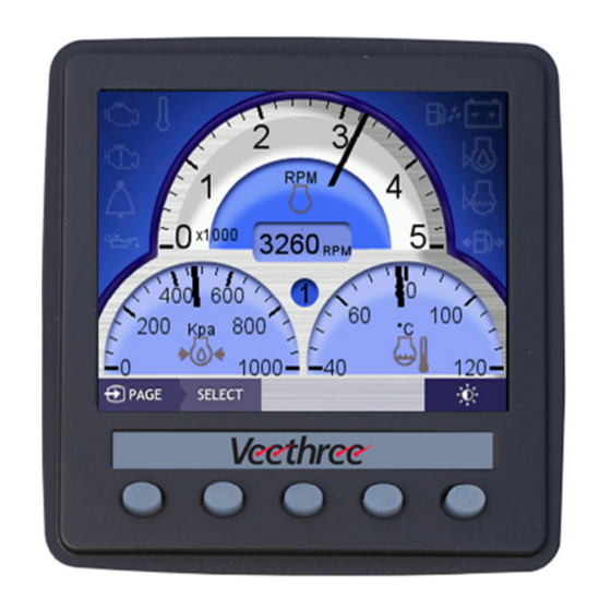
- Page 1 Marine Engine Gateway Monitor (EGM) Installation Guide...
-
Page 2: Table Of Contents
Contents Installing the Displays ................3 1.1 Mounting the Display ................3 1.2 Power Connections to the Display (all engine types) ......3 1.3 Attaching to NMEA 2000 (optional) ............3 1.4 Attaching to a J1939 Engines (CAN-bus) ..........4 1.5 Attaching to an Engine via Analogue Signals .......... -
Page 3: Installing The Displays
1. Installing the Displays The EGM supports up to three engine types (Non-electric, J1939 or NMEA 2000) and each display can be allocated to be Port (or single), Starboard or Centre. When mounting the displays the allocation of position is not important as this is done during the commissioning sequence. -
Page 4: Attaching To A J1939 Engines (Can-Bus)
If you have a dual station system you will need to connect to the NMEA 2000 network to share data between EGM’s even if you don’t have any other NMEA 2000 equipment. 1.4 Attaching to a J1939 Engines (CAN-bus) You will need to find the CAN-Low and the CAN-High from the Engine ECU or off of the Transmission –... -
Page 5: Attaching To A Fuel Level Sender
harness. The rudder sensor ground is connected to the spare black wire from the display (used for all analogue senders). 1.7 Attaching to a Fuel Level Sender The fuel level (one tank per display) can be measured from standard two wire fuel senders. -
Page 6: Commissioning The System
2 Configuring System Settings On completion of section 1, you are now ready to commission the system which will involve accessing the menu items described below to configure the various options. But first you will apply power to the system and check that the display(s) all power up correctly. -
Page 7: Engine Id
Analogue Settings. • Fuel Management. • Diagnostics. • Restore defaults. • 2.2 Engine ID The engine ID can be changed to either port/single engine, starboard engine or a centre engine, select the option that correctly describes the engine that the display is connected to. 2.3 Data Sources The ‘Data Source’... - Page 8 will need to set the engine settings to analogue and the speed setting to NMEA 0183.
-
Page 9: Nmea 2000 Settings
2.4 NMEA 2000 Settings In this menu you can choose the fluid level instance that is read from the NMEA 2000 network by the display. You can also, choose whether the gateway will be enabled or disabled, if enabled it transmits based on its Engine ID. -
Page 10: J1939 Settings
Source Address One: This is the Address of the J1939 Engine, and is used to Restrict what sources the EGM will accept J1939 from. It can also be set to GLB which means it will accept data from any source. -
Page 11: Analogue Settings
2.6 Analogue Settings The ‘Analogue Settings’ menu allows you to calibrate the signals from a non- electronic engine. RPM calibration is a simple multiplier, have the engine running on idle and adjust using the plus or minus until the number in brackets is the same as the RPM shown on your gauge, or is reading the same as the idle RPM from the Engine Manual. - Page 12 The screen title shows you which channel you have selected at the top. You then have three settings you can change, it also shows you the raw value the EGM is measuring, as well as the final data value, based on the chosen calibration.
-
Page 13: Fuel Management Settings
When connected to a non- electronic engine or a J1939 engine the fuel management information should be considered as just a guideline. In a single engine, single EGM system set it to master, in a multi EGM system you need ONE master the rest MUST be set to slave. -
Page 14: Diagnostics
2.8 Diagnostics The ‘Diagnostics Menu’ allows you to view all of the information that your display is receiving from every network input. The CAN viewer will allow you to check if and where the raw CAN data is being received and sent to. The UART viewer will allow you to view the raw NMEA 0183 data that is being received. - Page 15 The Data viewer allows you to view all of the data that the display is reading. The Data viewer will show you the data coming into the display, the units the data is displayed in and where the unit is getting its data from.
Need help?
Do you have a question about the EGM and is the answer not in the manual?
Questions and answers