
Related Manuals for OLIMEX AM3352-SOM


Summary of Contents for OLIMEX AM3352-SOM
- Page 1 AM3352-SOM System-on-Module board capable of Linux boot USER’S MANUAL Document revision A, June 2015 Designed by OLIMEX Ltd, 2015 All boards produced by Olimex LTD are ROHS compliant...
-
Page 2: Disclaimer
This document is intended only to assist the reader in the use of the product. OLIMEX Ltd. shall not be liable for any loss or damage arising from the use of any information in this document or any error or omission in such information or any incorrect use of the product. -
Page 3: Table Of Contents
2. Introduction to the chapter ....................... 8 2.1 Layout (top view) ........................8 2.2 Layout (bottom view) ....................... 9 CHAPTER 3: SETTING UP THE AM3352-SOM BOARD ........10 3. Introduction to the chapter ..................... 10 3.1 Electrostatic and electrical polarity warnings ..............10 3.2 Requirements .......................... - Page 4 OLIMEX© 2015 AM3352-SOM user's manual 6.3.1 SD/MMC slot ..............................23 6.5 GPIO connectors ........................24 6.5.1 AM_CON-GPIO1 (General Purpose Input/Output) 40pin connector ............ 25 6.5.2 AM_CON-GPIO2 (General Purpose Input/Output) 40pin connector ............ 26 6.5.3 AM_CON-GPIO3 (General Purpose Input/Output) 40pin connector ............ 27 6.6 AM_CON-LCD 40pin connector ..................
-
Page 5: Chapter 1: Overview
Thank you for choosing this single board computer from Olimex! This document provides a user’s guide for the AM3352-SOM board. As an overview, this chapter gives the scope of this document and lists the board’s features. The document’s organization is then detailed. -
Page 6: Target Market Of The Board
AM3352-SOM user's manual 1.2 Target market of the board Using the AM3352-SOM as a stand-alone development board would be more suitable for users with some hardware experience or people already familiar with other single-board Linux boards and designs. As mentioned in the previous chapter the board is meant to be implemented in a hardware design. -
Page 7: Board Variants
OLIMEX© 2015 AM3352-SOM user's manual 1.4 Board variants At the time of writing this document, AM3352-SOM is the only Olimex-made board featuring Texas Instruments AM3352. Other SOM boards that might be compared to functionality are: the well-supported A20-SOM, and the new powerhouse RK3188-SOM. -
Page 8: Chapter 2: Board Description
2. Introduction to the chapter Here you get acquainted with the main parts of the board. Note the names used on the board might differ from the names used below to describe them. For the actual names check the AM3352-SOM board itself. -
Page 9: Layout (Bottom View)
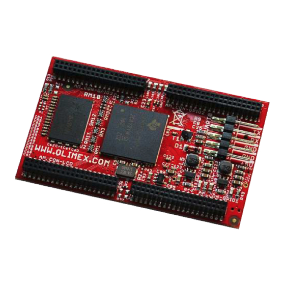
OLIMEX© 2015 AM3352-SOM user's manual 2.2 Layout (bottom view) The picture below shows the bottom side of the board and highlights the most important parts: The power LED indicates whether the board is powered properly. It is not connected to a processor pin. -
Page 10: Chapter 3: Setting Up The Am3352-Som Board
3.1 Electrostatic and electrical polarity warnings AM3352-SOM boards are shipped in a protective anti-static package. The board must not be exposed to high electrostatic potentials. A grounding strap or similar protective device should be worn when handling the board. Avoid touching the component pins or any other metallic element. -
Page 11: Requirements
AM3352-SOM user's manual 3.2 Requirements In order to set up the AM3352-SOM board optimally one or more additional items may be needed. These might be generally placed in two categories: Required – items that are needed in order to achieve minimum functionality;... -
Page 12: Powering The Board
3.3.1 Stand-alone powering If you use the board in stand-alone mode (e.g. it is neither attached to AM3352-SOM-EVB nor to any other board of peripherals) there are fewer options for powering it. Consider that you might need additional cables or connectors. You have the following options of powering the board: 1. -
Page 13: Mounted Powering
SOM-EVB, but what are the requirements to power AM3352-SOM-EVB? You need to provide 6V to 16V DC voltage to the power jack (named PWR) of AM3352-SOM- EVB board. The DC barrel jack has 2.0mm inner pin and 6.3mm hole. More information about the exact component might be found here: https://www.olimex.com/wiki/PWRJACK... -
Page 14: Interacting With The Board
AM3352-SOM user's manual 3.5 Interacting with the board The typical and recommended way of interacting with AM3352-SOM board is via a serial cable connected between the UART0 header and a personal computer. You would probably need a cable suitable for such a connection due to the fact that most personal computers lack a serial port nowadays. -
Page 15: Expanding The Debian File System Space
OLIMEX© 2015 AM3352-SOM user's manual 3.6 Expanding the Debian file system space The provided official Debian images have constant size but you may want to use a bigger microSD card. In case you don't know how to expand the file system space you can use the built-in shell script for this task. -
Page 16: Connecting And Calibrating A Display
However, there is only a 40-pin female connector AM_CON-LCD with a 0.05'' step. Unlike other OLIMEX Linux-enabled boards, the AM3352-SOM lacks a row of pins that allows the user to connect a display out-of-the-box. The board's AM_CON-LCD connector is female and has a smaller 0.05'' step (note that if you are using AM3352-SOM mounted on AM3352-SOM-EVB a... -
Page 17: Software Support
We usually try to provide extra details and best experiences with our products at our wordpress page: http://olimex.wordpress.com/. Another useful place is the Olimex forums where a lot of people share their experience and advice: https://www.olimex.com/forum/. -
Page 18: Chapter 4: The Am3352 Processor
OLIMEX© 2015 AM3352-SOM user's manual CHAPTER 4: THE AM3352 PROCESSOR 4. Introduction to the chapter In this chapter is located the information about the heart of AM3352 – its main processor. The information is a modified version of the datasheet provided by its manufacturers – Texas Instruments. -
Page 19: Block Diagram
OLIMEX© 2015 AM3352-SOM user's manual 4.2 Block diagram The block diagram was taken from the based on the AM3352's documentation. Page 19 of 36... -
Page 20: Chapter 5: Control Circuity
24 MHz quartz crystal Q2 is found at balls V11 and V10 of the AM3352 processor. 5.3 Power supply circuit A stand-alone AM3352-SOM consumes around 0.10A when connected to a 5V voltage source (provided at UART0 pins “GND” and “+5V”). -
Page 21: Chapter 6: Connectors And Pinout
The pins of the UART0 header might be used for serial communication between the board and a personal computer. They can also be used to power the whole AM3352-SOM board. In the case of a video output problem a cable might provide the needed feedback and greatly reduce the efforts needed to repair the board or to adjust the software setting. -
Page 22: Microsd Card Connector
OLIMEX© 2015 AM3352-SOM user's manual The UART0 header can also be used to power a stand-alone AM3352-SOM. This is the recommended way of powering a standalone AM3352 board. The voltage input pin (+) is named “+5V” and it is suitable for 5V DC external power supply unit. One of the two GND pins can be used as ground (-). -
Page 23: Sd/Mmc Slot
OLIMEX© 2015 AM3352-SOM user's manual 6.3.1 SD/MMC slot The schematic related to the SD/MMC (microSD connector) is shown below. SD/MMC slot is a microSD card slot connector, located on the bottom of the board. This slot is typically used for booting the OS, due to the larger capacities of the microSD cards (compared to SD or MMC cards). -
Page 24: Gpio Connectors
AM3352-SOM user's manual 6.5 GPIO connectors There are 3 GPIO connectors located on the bottom side of AM3352-SOM. They ease the access to processors pins. These connectors (and connector AM_CON-LCD) also provide a way to mount the board to a board of peripherals (like AM3352-SOM-EVB). -
Page 25: Am_Con-Gpio1 (General Purpose Input/Output) 40Pin Connector
OLIMEX© 2015 AM3352-SOM user's manual 6.5.1 AM_CON-GPIO1 (General Purpose Input/Output) 40pin connector AM_CON-GPIO1 connector Pin# Signal name Processor ball Pin# Signal name Processor ball 1 +5V 2 GND 3 3.3V 4 GND 5 P0_26/LCD_D21 6 P1_31/NDQS 7 P1_15/LCD_D16 8 P1_7/NDQ7... -
Page 26: Am_Con-Gpio2 (General Purpose Input/Output) 40Pin Connector
OLIMEX© 2015 AM3352-SOM user's manual 6.5.2 AM_CON-GPIO2 (General Purpose Input/Output) 40pin connector AM_CON-GPIO2 connector Pin# Signal name Processor ball Pin# Signal name Processor ball 3.3V USB1-VBUS USB1_ID USB1_DP USB1_CE USB1_DM 10 USB1_DRV 11 USB0-VBUS 12 USB0-ID 13 USB0_DP 14 USB0_CE... -
Page 27: Am_Con-Gpio3 (General Purpose Input/Output) 40Pin Connector
OLIMEX© 2015 AM3352-SOM user's manual 6.5.3 AM_CON-GPIO3 (General Purpose Input/Output) 40pin connector AM_CON-GPIO3 connector Pin# Signal name Processor ball Pin# Signal name Processor ball 3.3V P0_15/UART1_TXD P0_14/UART1_RXD P0_13/I2C2_SCL P0_12/I2C2_SDA P0_3/SPI0_D0(MISO) 10 P0_4/SPI0_D1(MOSI) 11 P0_2/SPI0_SCLK 12 P0_5/SPI0_CS0 13 P1_9/UART4_TXD 14 P1_8/UART4_RXD... -
Page 28: Am_Con-Lcd 40Pin Connector
*Pins 33 and 34 do not reach the processor due to the missing resistors r29 and r32. The values of these pins can be used to change the scanning mode (orientation) of the Olimex displays dynamically. The default scanning mode is “up to down, right to left“. -
Page 29: Jumper Description
(marked as NA in the schematic) 6.8 Additional hardware components The components below are mounted on the AM3352-SOM but are not discussed above. They are listed here for completeness: RST button – reset – used to reset the board NMI button –... - Page 30 OLIMEX© 2015 AM3352-SOM user's manual components missing from the circuit – not only the memory! You would also need to close the NAND_E SMT jumper. Note that we haven't performed any software tests with the NAND memory. Page 30 of 36...
-
Page 31: Chapter 7: Schematics
In this chapter is located information about the schematics describing logically and physically AM3352-SOM. 7.1 Eagle schematic AM3352 schematics may be found in the OLIMEX's GitHub repository: https://github.com/OLIMEX/SOM/tree/master/AM3352. You can download the whole repository as .zip without having a GitHub account. -
Page 32: Chapter 8: Revision History And Support
Board revision Notable changes Initial release of the board 8.3 Useful web links The web pages you can visit for more information about AM3352-SOM are: https://www.olimex.com/Products/SOM/AM3352/AM3352-SOM/ Wiki article of the board: https://www.olimex.com/wiki/AM3352-SOM A place for general questions, FAQ or friendly talk: https://www.olimex.com/forum/. -
Page 33: How To Purchase
8.4 How to purchase? You can purchase directly from our online shop or from any of our distributors. Note that usually it might be faster and cheaper to purchase Olimex products from our distributors. List of confirmed Olimex LTD distributors and resellers: https://www.olimex.com/Distributors. -
Page 34: Frequently Asked Questions
The tips above can also be used to prepare a microSD card with an Android image, suitable for a microSD card. Q: How to generate boot-able SD-card Linux image for AM3352-SOM? Build instructions and required files for the latest Debian images might be found at the wiki page of the board. - Page 35 VLAN for the router/switch/bridge or the network card otherwise the Ethernet connection to the AM3352-SOM-EVB board will fail. You can find a lot guides online on how to enable VLAN (or VLAN tagging) for your specific hardware and operating system.
-
Page 36: Product Support
All goods are checked before they are sent out. In the unlikely event that goods are faulty, they must be returned, to OLIMEX at the address listed on your order invoice. OLIMEX will not accept goods that have clearly been used more than the amount needed to evaluate their functionality.
Need help?
Do you have a question about the AM3352-SOM and is the answer not in the manual?
Questions and answers