Table of Contents
Advertisement
Advertisement
Table of Contents

Related Manuals for Ideal Boilers Classic RS 300


Summary of Contents for Ideal Boilers Classic RS 300
- Page 1 Wall hung, balanced flue, gas fired boilers Classic RS 330-360...
- Page 2 GENERAL Table 1 - General Data Boiler Size RS 330 RS 340 RS 350 RS 360 Gas supply connection " (BSP Female) Flow connection 22mm copper Return connection 22mm copper Maximum static water head m (ft.) 30.5 (100) Minimum static water head m (ft.) 0.45 (1.5) Electrical supply...
-
Page 3: Table Of Contents
GENERAL Classic RS Natural Gas only: I CONTENTS Data Badge: on top of the controls support B.G. Certified - P.I. No. 87AP108 Air Supply............... 6 Destination Countries: GB & IE Appliance type: C Boiler Assembly - Exploded view ......... 8 Models G.C. -
Page 4: Location Of Boiler
GENERAL BS. 5440: Part 1 Flues for gas appliances of rated input not INTRODUCTION exceeding 60 kW. The Classic RS 330-360 is a range of automatically fully BS. 5440: Part 2 Ventilation for gas appliances of rated input controlled, wall mounted, balanced flue, gas boilers. not exceeding 60 kW. -
Page 5: Boiler Water Connections
GENERAL 1 BOILER WATER CONNECTIONS 1. This appliance is NOT suitable for use in a direct hot water system. 2. If the boiler is to be used on a sealed system, an Overheat Thermostat Kit is available and must be installed in accordance with the instructions supplied with the kit. -
Page 6: Gas Supply
GENERAL Table 3 - Balanced flue terminal position Compartment Installations Terminal Position Minimum Spacing A compartment used to enclose the boiler MUST be designed and 330-340 350-360 constructed specially for this purpose. An existing cupboard or compartment may be used, providing it is modified for the purpose. 1a. -
Page 7: Water Treatment
GENERAL 3. Both air vents MUST communicate with the same room or Caradon Ideal Limited recommend Water Treatment in accordance with the Benchmark Guidance Notes on Water internal space or MUST be on the same wall to outside air. Treatment in Central Heating Systems. 4. -
Page 8: Boiler Assembly - Exploded View
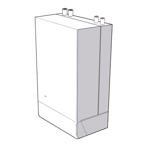
INSTALLATION 3 BOILER ASSEMBLY - Exploded View Classic RS 330 shown Programmer Controls support 18.1 Data badge LEGEND Boiler thermostat Heat exchanger Pipe - Return assy. Control thermostat knob Flue baffles Collector hood Balanced flue terminal Hook bolt kit assy. Combustion chamber 44B. - Page 9 INSTALLATION UNPACKING The boiler is supplied fully assembled in Pack A, together with a Pack A Contents standard flue assembly for lengths up to 305mm (12") in Pack B. - Hardware Pack (listed below) Unpack and check the contents. - Installation & Servicing Instructions - User's Instructions.
-
Page 10: Low Head Installations
INSTALLATION OPEN VENT SYSTEM REQUIREMENTS - Fully pumped Feed / expansion 450 (18") The system should be vented directly off the boiler flow pipe, as close to the boiler cistern Mimimum as possible. The cold feed entry should be inverted and MUST be positioned Water level between the pump and the vent, and not more than 150mm (6") away from the... - Page 11 INSTALLATION SEALED SYSTEM REQUIREMENTS Non-return valve Automatic air vent Hosepipe (disconnect after filling) Hose unions Additional stop valve Temporary hose (disconnect Hose connector Double check valve after filling) assembly (note direction of flow) Note. 4. Expansion Vessel The method of filling, refilling, topping up or flushing sealed primary hot water circuits from the mains via a temporary hose a.
- Page 12 INSTALLATION 10 SEALED SYSTEM REQUIREMENTS - continued draw-off points at a lower level then a double check 7. Mains Connection valve shall be installed upstream of the draw-off point. There must be no direct connection to the mains water supply c.
-
Page 13: Wall Mounting Template
INSTALLATION 11 WALL MOUNTING TEMPLATE 1. Tape the template to the wall in the selected position. Ensure squareness by use of a plumbline, as shown. 2. Mark out the position of the 3 wallplate screws, choosing one from each group of 3 holes. Also mark the position of the hole for the duct, the jacking screw and the top cover plate screws. -
Page 14: Mounting The Boiler
INSTALLATION 14 MOUNTING THE BOILER Flue Alignment It is 1. Lift the boiler onto the wall mounting plate, entering the projecting flue duct into the opening cut in the wall, and most lowering the 2 slots in the boiler back panel onto the angled important tabs on the top of the wall mounting plate. -
Page 15: Electrical Supply
INSTALLATION 16 GAS CONNECTION WATER CONNECTIONS 1. Remove the plastic plugs from the A MINIMUM gas pressure of 20 mbar (8 in.w.g.) MUST be available at the boiler flow and return pipes. inlet, with the boiler operating. The main gas cock is on the left hand side of the gas control valve, as shown. 2. - Page 16 INSTALLATION 20 PICTORIAL WIRING Gas valve Ignition/ detection electrode LEGEND b blue bk black br brown MAINS y yellow w white Printed ciruit board or orange v violet p pink gy grey y/g yellow/green Overheat thermostat (if fitted) Clas 2110 21 MID POSITION VALVE Pumped only Notes.
- Page 17 INSTALLATION 22 TWO SPRING CLOSED VALVES Pumped only Notes. 1. Some earth wires are omitted for clarity. Ensure proper earth continuity when wiring. 2. Numbering of terminals on thermostats is specific to the manufacturer. 3. This is a fully controlled system - set the boiler thermostat to maximum.
-
Page 18: Frost Protection
INSTALLATION 24 FROST PROTECTION Designation of the terminals will vary, but the programmer and Central heating systems fitted wholly inside the house do not thermostat manufacturer's leaflets will give full details. normally require frost protection as the house acts as a 'storage heater' and can normally be left at least 24 hrs. -
Page 19: Fault Finding
INSTALLATION 26 INITIAL LIGHTING LEGEND A Sightglass B Gas service cock C Inlet pressure test point D Thermostat knob E Main burner pressure adjuster F Burner pressure test point G Overheat stat reset button 1. Check that all drain cocks are CLOSED and any valves in 8. -
Page 20: Handing Over
INSTALLATION 27 GENERAL CHECKS Make the following checks for correct operation: The temperatures quoted below are approximate and vary between installations. 1. Set the boiler thermostat knob to position 6 and operate the mains on/off switch. Check that the main burner lights and extinguishes in response. -
Page 21: Gas Supply
SERVICING f. Check that the flue terminal is unobstructed and that the 29 SCHEDULE flue system is sealed correctly. To ensure the continued safe and efficient operation of the g. If the appliance has been installed in a compartment, check appliance it is recommended that it is checked at regular intervals that the ventilation areas are clear. -
Page 22: Initial Lighting
SERVICING 32 CLEANING THE FLUEWAYS 33 CLEANING THE BURNER AND PILOT ASSEMBLY 1. Remove the collector hood by undoing the front tie rod nuts and releasing the tie rods from the combustion chamber. Withdraw the rods. 1. Brush off any deposits that may have fallen on to the burner head (ensuring the flame ports are unobstructed) 2. -
Page 23: Replacement Of Parts
SERVICING REPLACEMENT OF PARTS 36 GENERAL When replacing any component: Note. In order to assist fault finding, the control box printed circuit board is fitted with 2 indicator lights which represent the 1. Isolate the electricity supply. following boiler conditions: 2. -
Page 24: Pilot Burner Replacement
SERVICING 39 CONTROL THERMOSTATREPLACEMENT 1. Refer to Frame 36. 2. Pull the knob off the shaft. 3. Remove the control box fixing screws. Pull the box forward and downward to disengage. 4. Remove the screws securing the thermostat control to the control box. 5. -
Page 25: Ignition Electrode And Lead Replacement
SERVICING 41 IGNITION ELECTRODE AND LEAD REPLACEMENT 1. Refer to Frame 36. 2. Remove the burner and air box assembly. Refer to Frame 43. 3. Remove the electrode retaining nut. 4. Remove the pilot shield. 5. Remove the ignition electrode and integral lead. 6. -
Page 26: Gas Control Valve Replacement
SERVICING 44 GAS CONTROL VALVE REPLACEMENT Note. Refer also to Frame 53 of 'Exploded Views' for illustration of the procedure detailed below. 1. Refer to Frame 36. 2. Remove the burner and air box assembly. Refer to Frame 43. 3. Remove the control box securing screws. Pull the box forward Gas cock union and downward to disengage. -
Page 27: Heat Exchanger Replacement
SERVICING 47 HEAT EXCHANGER REPLACEMENT 7. Remove the thermostat sensors from the pockets on the heat exchanger by removing the M3 screws and plates. Note. Refer to Frame 3 (Boiler Assembly - Exploded 8. Slacken 3 turns only the 4 heat exchanger / inter-panel view) for illustration of the procedure detailed below. -
Page 28: Fault Finding
FAULT FINDING Reset the overheat 'stat. Set control Check mains supply and fuses. START 'stat to maximum. Allow the boiler to Check programmer and system reach temperature - if the overheat Check that the Mains On thermostats are all ON. 'stat trips again, measure flow neon 'I3' is illuminated. -
Page 29: Short List Of Parts
When replacing any part on this appliance, use only spare parts that you can be assured conform to the safety and performance specification that we require. Do not use reconditioned or copy parts that have not been clearly authorised by Ideal Boilers. - Page 30 SHORT LIST OF PARTS 50 SHORT PARTS 18.1 Cla 2124 51 BOILER CASING ASSEMBLY Classic RS - Installation & Servicing...
-
Page 31: Burner Assembly - Exploded View
SHORT LIST OF PARTS 52 CONTROL BOX - Exploded View LEGEND 19. Control box 25.Boiler thermostat 23. Printed circuit board 26. Thermostat knob Optional Extra 53 BURNER ASSEMBLY - Exploded view LEGEND 10. Burner manifold 11. Air box and pilot assembly. 13. - Page 32 Technical Training The Ideal Boilers Technical Training Centre offers a series of first class training courses for domestic, commercial and industrial heating installers, engineers and system specifiers. For details of courses please ring: ....01482 498 432 The code of practice for the installation, commissioning &...
Need help?
Do you have a question about the Classic RS 300 and is the answer not in the manual?
Questions and answers