Sun Microsystems Fire V240 Administration Manual
Hide thumbs
Also See for Fire V240:
- Administration manual (114 pages) ,
- Manual (102 pages) ,
- Installation manual (70 pages)
Table of Contents

Related Manuals for Sun Microsystems Fire V240


Summary of Contents for Sun Microsystems Fire V240
- Page 1 Sun Fire V210 and V240 Servers Administration Guide Sun Microsystems, Inc. 4150 Network Circle Santa Clara, CA 95054 U.S.A. 650-960-1300 Part No. 816-4826-11 April 2003, Revision A Send comments about this document to: docfeedback@sun.com...
- Page 2 Sun, Sun Microsystems, le logo Sun, AnswerBook2, docs.sun.com, et Solaris sont des marques de fabrique ou des marques déposées, ou marques de service, de Sun Microsystems, Inc. aux Etats-Unis et dans d’autres pays. Toutes les marques SPARC sont utilisées sous licence et sont des marques de fabrique ou des marques déposées de SPARC International, Inc.
-
Page 3: Table Of Contents
To Turn The Locator LED Off 6 Front Panel Features 7 On/Standby Switch 7 Hard disk drives 9 DVD-ROM Drive 9 System Configuration Card (SCC) 10 Keyswitch (Sun Fire V240 server only) 12 Back Panel Features 14 I/O Ports 15 Network Status Indicators 15 Contents... - Page 4 Removing a SCSI Hard Disk Drive With Solaris Running 30 Removing And Replacing The DVD-ROM Drive 32 To Replace The DVD-ROM Drive 33 Sun Fire V240 Server: Removing and Replacing a Power Supply Unit 34 To Remove a Power Supply Unit 34 To Replace a Power Supply Unit 34 Sun™...
- Page 5 ALOM Management Ports 39 Setting the admin Password 39 Basic ALOM Functions 40 To Switch To The ALOM Prompt 40 To Switch To The Server Console Prompt 40 Sun Management Center 41 Sun Management Center 42 How Sun Management Center Works 42 Other Sun Management Center Features 43 Using Sun Management Center 43 Hardware Diagnostic Suite 44...
- Page 6 OpenBoot Diagnostics 59 To Start OpenBoot Diagnostics 60 Controlling OpenBoot Diagnostics Tests 61 OpenBoot Commands 63 To Run OpenBoot Commands 66 Operating Environment Diagnostic Tools 67 Error and System Message Log Files 67 Solaris System Information Commands 67 To Run Solaris System Information Commands 75 Recent Diagnostic Test Results 76 To View Recent Test Results 76 OpenBoot Configuration Variables 76...
- Page 7 Location Of Front Panel Features 7 FIGURE 1-4 Location Of Hard Disk Drive Service Indicators (Sun Fire V120 Server Shown) 9 FIGURE 1-5 Location Of The Keyswitch (Sun Fire V240 Server Only) 13 FIGURE 1-6 Keyswitch Positions (Sun Fire V240 Server Only) 13 FIGURE 1-7...
- Page 8 watch-net-all Diagnostic Output Message 80 FIGURE 6-5 Figures viii...
- Page 9 TABLE 1-8 Network Speed Indicators 16 TABLE 1-9 Power Supply Unit Indicators 17 TABLE 1-10 Power Supply Unit Ready To Remove Indicator (Sun Fire V240 only) 17 TABLE 1-11 Optional Components 18 TABLE 1-12 What ALOM Monitors 38 TABLE 3-1...
- Page 10 Using Solaris Information Display Commands 75 TABLE 6-6 Sun Fire V210 and V240 Servers Administration Guide • April 2003...
-
Page 11: Before You Read This Book
Preface The Sun Fire V210 and V240 Servers Administration Guide is intended to be used by experienced system administrators. As well as general descriptive information about the Sun Fire V210 and V240 servers, it includes detailed instructions on the various server administration tasks. - Page 12 Solaris Handbook for Sun Peripherals Other software documentation that you received with your system xii Sun Fire V210 and V240 Servers Administration Guide • April 2003...
-
Page 13: Typographic Conventions
Typographic Conventions Typeface Meaning Examples The names of commands, files, Edit your.login file. AaBbCc123 and directories; on-screen Use ls -a to list all files. computer output % You have mail. What you type, when contrasted AaBbCc123 with on-screen computer output Password: AaBbCc123 Book titles, new words or terms,... -
Page 14: Related Documentation
Related Documentation Application Title Part Number Unpacking Sun Fire V210 and V240 Servers Quick 816-4824-xx Start Guide Installation Sun Fire V210 and V240 Servers 817-1462-xx Compliance and Safety Manual Sun Fire V210 and V240 Servers 816-4825-xx Installation Guide Lights-Out Management ALOM Online Help 817-0076-xx Latest information... -
Page 15: Introduction
C H A P T E R Introduction This chapter describes the Sun Fire V210 and V240 servers and gives an overview of their main features. It contains the sections: “Overview of the Servers” on page 2 “Bezel Features” on page 4 “Back Panel Features”... -
Page 16: Overview Of The Servers
Overview of the Servers The Sun Fire V210 Server FIGURE 1-1 Sun Fire V210 Server The Sun Fire V210 server is a commercial grade server in a 1 RU high package. It uses the UltraSPARC IIIi processor and can be configured with either one or two processors. -
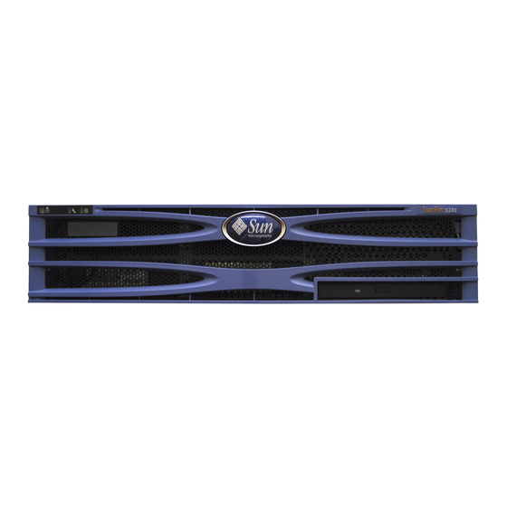
Page 17: Sun Fire V240 Server
The Sun Fire V240 Server FIGURE 1-2 Sun Fire V240 Server The Sun Fire V240 server is a commercial grade server in a 2 RU high package. It uses the UltraSPARC IIIi processor and can be configured with either one or two processors. -
Page 18: Differences Between The Servers
Front and rear service indicators Differences Between The Servers Sun Fire V210 and V240 Server: Differences TABLE 1-1 Sun Fire V210 server Sun Fire V240 server 1 RU high 2 RU high Height 1x64-bit 33/66 MHz 3.3V PCI 1x64-bit 33/66 MHz 3.3V PCI... -
Page 19: Server Status Indicators
Locator Service Activity Location of Status Indicators (Sun Fire V210 Server Shown) FIGURE 1-3 Server Status Indicators The server has three LED status indicators. They are located on the front bezel, and repeated on the rear panel. A summary of the indicators is given in TABLE 1-2 Server Status Indicators TABLE 1-2... -
Page 20: To Turn The Locator Led On
To Turn The Locator LED On Do one of the following: As root, type # /usr/sbin/locator -n At the ALOM command-line interface, type: sc> setlocator on To Turn The Locator LED Off Do one of the following: As root, type: # /usr/sbin/locator -f At the ALOM command-line interface, type: sc>... -
Page 21: Front Panel Features
The front panel contains the following: On/Standby switch Hard disk drive DVD-ROM drive System configuration card Sun Fire V240 server only: keyswitch Hard disk drive DVD-ROM drive System configuration card On/Standby switch Location Of Front Panel Features FIGURE 1-4 On/Standby Switch Access to the On/Standby switch is by opening the front bezel. -
Page 22: Table 1-3 On/Standby Switch Actions And Results
Press and immediately release Press and hold down for more than 4 seconds The results of these actions are summarised in TABLE 1-3 On/Standby Switch Actions and Results TABLE 1-3 Server Power State Press and release Press down for more than 4 seconds On (with Solaris Software performs orderly Server enters Standby state... -
Page 23: Hard Disk Drives
Hard disk drives The Sun Fire V210 server has slots for up to two hard disk drives. The Sun Fire V240 server has slots for up to four. The slots accept any Sun LVD SCSI hard disk drive conforming to the 1-inch SCA-2 form factor. -
Page 24: System Configuration Card (Scc)
For information on DVD-ROM drive installation, see “Removing And Replacing The DVD-ROM Drive” on page 32. System Configuration Card (SCC) The system configuration card is housed in a slot behind the front bezel, next to the On/Standby switch (see ). The card contains unique network identity FIGURE 1-4 information, including the MAC address and hostid (known as the idprom), and the OpenBoot™... - Page 25 OBP Configuration Parameters Stored On The System Configuration Card TABLE 1-6 Parameter Default Description Suppress all messages if true and diag- silent-mode? false switch? is false scsi-id of the scsi controller scsi-initiator-id If true, use custom OEM logo, otherwise, oem-logo? false use Sun logo If true, use custom OEM banner...
-
Page 26: Keyswitch (Sun Fire V240 Server Only)
Identifies number and order in which pci pcia-probe-list slots are probed Keyswitch (Sun Fire V240 server only) The Sun Fire V240 server has a keyswitch that provides control over the following aspects of the server’s operation: Power state Security level... -
Page 27: Figure 1-6 Location Of The Keyswitch (Sun Fire V240 Server Only)
Keyswitch Location Of The Keyswitch (Sun Fire V240 Server Only) FIGURE 1-6 The keyswitch has four positions, each of which forces the server into a different mode of behaviour. The key has an integral pointer, which you need to tell accurately which position the keyswitch is in. -
Page 28: Back Panel Features
Keyswitch positions and the behaviours they force are given in TABLE 1-7 Keyswitch Position and Server Behaviours TABLE 1-7 Keyswitch position Forced Server Behaviour Normal Normal operation Diagnostics Full POST during system boot Locked Disable on/standby switch Write-protect ALOM Flash PROM Write-protect OBP/POST Flash PROM Disable suspension to OBP/Kadb Forced Standby... -
Page 29: I/O Ports
NET MGT SERIAL Ethernet SCSI I/O Ports On A Sun Fire V240 Server FIGURE 1-9 I/O Ports The I/O ports on the rear of the Sun Fire V210 and V240 are arranged as shown in . For more information on the I/O ports, refer to the Sun... -
Page 30: Usb Ports
The network status indicators convey: Network link Network speed (does not apply to the NET MGT port) For a summary of what the network link indicators mean, see TABLE 1-8 Network Link Indicators TABLE 1-8 LED Colour LED State Network Link Status Green Link is established. -
Page 31: Power Supply Unit (Psu)
The PSU is operating normally. The Sun Fire V240 server has dual redundant PSUs. This server has an additional LED indicator which tells you when a power supply unit is ready to be removed with the server running. (The Sun Fire V210 server has a single PSU and does not support this function.) -
Page 32: Optional Components
Optional Components The following table lists the optional components that are available for the Sun Fire V210 and V240 server. Optional Components TABLE 1-12 Component Description Order Number Storage disk 36 GB 10000 RPM 1-inch SCSI X5244A Memory 256 MB X7402A 512 MB X7403A... -
Page 33: System Prompts
System Prompts The following default server prompts are used by the Sun Fire V210 and V240 servers: ok—OpenBoot PROM (OBP) prompt sc—Advanced Lights-Out Manager (ALOM) prompt #—Solaris superuser (Bourne and Korn shell) shows the relationship between the three prompts and how to change FIGURE 1-11 from one to the other. - Page 34 Sun Fire V210 and V240 Servers Administration Guide • April 2003...
-
Page 35: Removing And Replacing Components
C H A P T E R Removing and Replacing Components This chapter tells you how to remove and replace the components that are located behind the server’s front bezel. The procedures documented in this chapter do not require the attention of qualified service personnel. Caution –... -
Page 36: Replaceable Components
Replaceable Components Open the bezel down to access these components: System Configuration Card Hard disk drives DVD-ROM drive Note – Access to any other component requires the removal of the server’s lid, and involves procedures that must be carried out by trained personnel only. Avoiding Electrostatic Discharge To Avoid Electrostatic Discharge While Working On The Front Panel... -
Page 37: Figure 2-1 Opening The Bezel On A Sun Fire V210 Server
2. Open the bezel by rotating it down on its hinges. Opening The Bezel on a Sun Fire V210 Server FIGURE 2-1 Opening The Bezel on a Sun Fire V210 Server FIGURE 2-2 Note – Always grip the bezel at both ends to open it. Do not attempt to open it using a single point of grip. -
Page 38: Controlling Server Power
Read the documentation supplied with the device for specific instructions. 3. Open the front bezel. 4. Sun Fire V240 only: insert the system key into the keyswitch and set it to the Normal or Diagnostics position. 5. Press the On/Standby switch. -
Page 39: To Power Off Using The On/Standby Switch
5. Wait for the front panel green LED to go out. 6. Sun Fire V240 only: remove the system key from the keyswitch and store it in the clip on the back of the front bezel. -
Page 40: Figure 2-3 Inserting A System Configuration Card (Sun Fire V210 Server Shown)
2. Open the front bezel on both servers. See “To Open The Front Bezel” on page 22. 3. Remove the cable ties that secure the system configuration cards, and remove the cards. 4. Insert the system configuration card from the old server into the new one. 5. -
Page 41: Removing And Replacing Hard Disk Drives
Removing and Replacing Hard Disk Drives Caution – The server and hard disk drives contain electronic parts that are extremely sensitive to static electricity. Wear a grounded antistatic wrist strap when you carry out this procedure. Removing A Hard Disk Drive The hard disk drives are hot-pluggable modules. -
Page 42: Installing A Hard Disk Drive
Installing A Hard Disk Drive Caution – The server and hard disk drives contain electronic parts that are extremely sensitive to static electricity. Wear a grounded antistatic wrist strap when you carry out this procedure. Inserting a Hard Disk Drive (Sun Fire V210 Server Shown) FIGURE 2-4 5. -
Page 43: Installing A Scsi Hard Disk Drive With Solaris Running
Installing a SCSI Hard Disk Drive With Solaris Running Before performing the instructions in this section, install the Hard Disk Drive by following the instructions in “Installing A Hard Disk Drive” on page 28. Use the instructions below in conjunction with the cfgadm(M) man page. 1. -
Page 44: Removing A Scsi Hard Disk Drive With Solaris Running
4. Confirm that the disk is now connected and configured. Type: # cfgadm -al Ap_Id Type Receptacle Occupant Condition scsi-bus connected configured unknown c0::dsk/c0t0d0 CD-ROM connected configured unknown scsi-bus connected configured unknown c1::dsk/c1t0d0 disk connected configured unknown c1::dsk/c1t1d0 disk connected configured unknown scsi-bus... - Page 45 2. Get the correct Ap_Id label for the Hard Disk Drive that you want to remove. Type: # cfgadm -al Ap_Id Type Receptacle Occupant Condition scsi-bus connected configured unknown c0::dsk/c0t0d0 CD-ROM connected configured unknown scsi-bus connected configured unknown c1::dsk/c1t0d0 disk connected configured unknown...
-
Page 46: Removing And Replacing The Dvd-Rom Drive
5. Confirm that the Hard Disk Drive you want to remove from the server is no longer visible to the Operating System. Type the following: # format Searching for disks...done AVAILABLE DISK SELECTIONS: 0. c0t0d0 <SUN36G cyl 24427 alt 2 hd 27 sec 107> /pci@1f,0/pci@1/scsi@8/sd@0,0 6. -
Page 47: To Replace The Dvd-Rom Drive
5. Insert the new DVD-ROM drive. 6. Press it home firmly until the clips engage with the server’s chassis. 7. Close the bezel. Removing a DVD-ROM Drive (Sun Fire V240 Shown) FIGURE 2-5 Chapter 2 Removing and Replacing Components... -
Page 48: Sun Fire V240 Server: Removing And Replacing A Power Supply Unit
Sun Fire V240 Server: Removing and Replacing a Power Supply Unit The Sun Fire V240 server has dual-redundant power supplies. You can swap one power supply while the other is still running. The Sun Fire V210 server has a single power supply. Swapping it requires the attention of qualified service personnel. - Page 49 3. At the ALOM prompt, type: sc> poweron PSx Where x is the power supply unit identifier, 0 or 1. Chapter 2 Removing and Replacing Components...
- Page 50 Sun Fire V210 and V240 Servers Administration Guide • April 2003...
-
Page 51: Sun™ Advanced Lights-Out Manager
C H A P T E R Sun™ Advanced Lights-Out Manager This chapter gives an overview of the Sun Advanced Lights-Out Manager (ALOM) software. The chapter contains: “Sun™ Advanced Lights-Out Manager 1.0 (ALOM)” on page 38 “ALOM Management Ports” on page 39 “Setting the admin Password”... -
Page 52: Sun™ Advanced Lights-Out Manager 1.0 (Alom)
Sun™ Advanced Lights-Out Manager 1.0 (ALOM) Both the Sun Fire V210 server and the Sun Fire V240 server are shipped with Sun™ Advanced Lights Out Manager (ALOM) 1.0 installed. The system console is directed to ALOM by default and is configured to show server console information on startup. -
Page 53: Alom Management Ports
What ALOM Monitors TABLE 3-1 Component Information Server front panel Keyswitch position and LED status Voltage Status and thresholds SCSI and USB circuit breakers Status ALOM Management Ports The default management port is labeled SERIAL MGT. This port uses an RJ-45 connector and is for server management only—it supports only ASCII connections to an external console. -
Page 54: Basic Alom Functions
Basic ALOM Functions This section covers some basic ALOM functions. For comprehensive documentation, refer to the ALOM Online Help which is included on the Sun Fire V210 and V240 Server Documentation CD. To Switch To The ALOM Prompt 1. Type the default keystroke sequence: # #. -
Page 55: Sun Management Center
C H A P T E R Sun Management Center This chapter describes SunMC. The chapter contains the sections: “Sun Management Center” on page 42 “Hardware Diagnostic Suite” on page 44... -
Page 56: Sun Management Center
Sun Management Center Sun Management Center software provides enterprise-wide monitoring of Sun servers and workstations, including their subsystems, components, and peripheral devices. The system being monitored must be up and running, and you need to install all the proper software components on various systems in your network. Sun Management Center lets you monitor the following on the Sun Fire V210 and V240 server. -
Page 57: Other Sun Management Center Features
Other Sun Management Center Features Sun Management Center software provides you with additional tools, which can operate with management utilities made by other companies. The tools are an informal tracking mechanism and the optional add-on, Hardware Diagnostics Suite. Informal Tracking Sun Management Center agent software must be loaded on any system you want to monitor. -
Page 58: Hardware Diagnostic Suite
For detailed instructions, see the Sun Management Center Software User’s Guide. Obtaining the Latest Information For the latest information about this product, go to the Sun Management Center Web site: http://www.sun.com/sunmanagementcenter. Hardware Diagnostic Suite The Sun Management Center features an optional Hardware Diagnostic Suite, which you can purchase as an add-on. - Page 59 platform status information. In addition, you must install and set up Sun Management Center agent software on the systems to be monitored. Finally, you need to install the console portion of Sun Management Center software, which serves as your interface to the Hardware Diagnostic Suite. Instructions for setting up Sun Management Center, as well as for using the Hardware Diagnostic Suite, can be found in the Sun Management Center Software User’s Guide.
- Page 60 Sun Fire V210 and V240 Servers Administration Guide • April 2003...
-
Page 61: Sun Vts
C H A P T E R Sun VTS This chapter describes SunVTS. The chapter contains the following sections: “SunVTS” on page 48... -
Page 62: Sunvts
SunVTS SunVTS is a software suite that performs system and subsystem stress testing. You can view and control a SunVTS session over a network. Using a remote machine, you can view the progress of a testing session, change testing options, and control all testing features of another machine on the network. -
Page 63: Using Sunvts
If your site uses SEAM security, you must have the SEAM client and server software installed in your networked environment and configured properly in both Solaris and SunVTS software. If your site does not use SEAM security, do not choose the SEAM option during SunVTS software installation. -
Page 64: To Find Out Whether Sunvts Is Installed
SunVTS Tests TABLE 5-1 SunVTS Test Description env6test Tests the environmental devices ssptest Tests ALOM hardware devices i2c2test Tests I2C devices for correct operation To Find Out Whether SunVTS Is Installed Type: # pkginfo -l SUNWvts If SunVTS software is loaded, information about the package will be displayed. If SunVTS software is not loaded, you will see the following error message: ERROR: information for “SUNWvts”... - Page 65 SunVTS Quick Reference Card provides an overview of how to use the SunVTS CDE interface. SunVTS Test Reference Manual provides details about each individual SunVTS test. Chapter 5 Sun VTS...
- Page 66 Sun Fire V210 and V240 Servers Administration Guide • April 2003...
-
Page 67: Diagnostics
C H A P T E R Diagnostics This chapter describes the diagnostics tools available to the Sun Fire V210 and V240 servers. The chapter contains the sections: “Overview Of Diagnostic Tools” on page 54 “Sun™ Advanced Lights-Out Manager” on page 55 “Status Indicators”... -
Page 68: Overview Of Diagnostic Tools
Overview Of Diagnostic Tools Sun provides a range of diagnostic tools for use with the Sun Fire V210 and V240 server. Diagnostic tools are summarized in TABLE 6-1 Summary of Diagnostic Tools TABLE 6-1 Remote Diagnostic Tool Type What It Does Accessibility and Availability Capability ALOM... -
Page 69: Sun™ Advanced Lights-Out Manager
Center Sun™ Advanced Lights-Out Manager Both the Sun Fire V210 server and the Sun Fire V240 server are shipped with Sun™ Advanced Lights Out Manager (ALOM) pre-installed. ALOM enables you to monitor and control your server over either a serial connection (using the SERIAL MGT port), or Ethernet connection (using the NET MGT port). -
Page 70: Status Indicators
for a list of the components monitered by ALOM and the information TABLE 6-2 it provides for each. What ALOM Monitors TABLE 6-2 Item Monitored What ALOM Reveals Hard disk drives Presence and status System and CPU fans Speed and status CPUs Presence, temperature and any thermal warning or failure conditions... -
Page 71: To Start Post Diagnostics
POST detects most system faults and is located in the motherboard OpenBoot™ PROM. POST can be set to run by the OpenBoot program at power up by setting two environment variables, the diag-switch? and the diag-level flag, which are stored on the system configuration card. POST runs automatically when the system power is applied, or following an automatic system reset, if all of the following conditions apply: diag-switch? is set to true (default is false) -
Page 72: Controlling Post Diagnostics
5. When you have finished running POST, restore the value of diag-switch? to false by typing: ok setenv diag-switch? false Resetting diag-switch? to false minimizes boot time. Controlling POST Diagnostics You control POST diagnostics (and other aspects of the boot process) by setting OpenBoot configuration variables. -
Page 73: Openboot Diagnostics
OpenBoot Configuration Variables (Continued) TABLE 6-3 OpenBoot Configuration Variable Description and Keywords Specifies the class of reset event that causes power-on self-tests (or OpenBoot post-trigger Diagnostics tests) to run. These variables can accept single keywords as well as combinations of the first three keywords separated by spaces. For details, see “To View And Set OpenBoot Configuration Variables”... -
Page 74: To Start Openboot Diagnostics
To Start OpenBoot Diagnostics 1. Type: ok setenv diag-switch? true ok setenv auto-boot? false ok reset-all 2. Type: ok obdiag This command displays the OpenBoot Diagnostics menu. See TABLE 6-4 Sample obdiag Menu TABLE 6-4 obdiag 1 i2c@0,320 2 ide@d 3 network@2 4 network@2,1 5 rtc@0,70... -
Page 75: Controlling Openboot Diagnostics Tests
Controlling OpenBoot Diagnostics Tests Most of the OpenBoot configuration variables you use to control POST (see TABLE 6-3 on page 58) also affect OpenBoot Diagnostics tests. Use the diag-level variable to control the OpenBoot Diagnostics testing level. Use test-args to customize how the tests run. By default, test-args is set to contain an empty string. - Page 76 The test and test-all Commands You can also run OpenBoot Diagnostics tests directly from the ok prompt. To do this, type the test command, followed by the full hardware path of the device (or set of devices) to be tested. For example: ok test /pci@x,y/SUNW,qlc@2 Note –...
-
Page 77: What Openboot Diagnostics Error Messages Tell You
What OpenBoot Diagnostics Error Messages Tell You OpenBoot Diagnostics error results are reported in a tabular format that contains a short summary of the problem, the hardware device affected, the subtest that failed, and other diagnostic information. displays a sample OpenBoot CODE EXAMPLE 6-1 Diagnostics error message. - Page 78 Caution – If you used the halt command or the Stop-A key sequence to reach the ok prompt, then issuing the probe-scsi or probe-scsi-all command can hang the system. The probe-scsi command communicates with all SCSI devices connected to on- board SCSI controllers.
- Page 79 sample probe-scsi-all Command Output CODE EXAMPLE 6-3 probe-ide The probe-ide command communicates with all Integrated Drive Electronics (IDE) devices connected to the IDE bus. This is the internal system bus for media devices such as the DVD drive. Caution – If you used the halt command or the Stop-A key sequence to reach the ok prompt, then issuing the probe-ide command can hang the system.
-
Page 80: To Run Openboot Commands
show-devs Command The show-devs command lists the hardware device paths for each device in the firmware device tree. shows some sample output. CODE EXAMPLE 6-5 /pci@1d,700000 /pci@1c,600000 /pci@1e,600000 /pci@1f,700000 /memory-controller@1,0 /SUNW,UltraSPARC-IIIi@1,0 /memory-controller@0,0 /SUNW,UltraSPARC-IIIi@0,0 /virtual-memory /memory@m0,0 /aliases /options /openprom /chosen /packages@0,320//packages/terminal-emulator /packages/disk-label /packages/deblocker /packages/SUNW,builtin-drivers ... -
Page 81: Operating Environment Diagnostic Tools
Operating Environment Diagnostic Tools If a system passes OpenBoot Diagnostics tests, it normally attempts to boot its multiuser operating environment. For most Sun systems, this means the Solaris operating environment. Once the server is running in multiuser mode, you have access to the software-based diagnostic tools, SunVTS and Sun Management Center. - Page 82 CODE EXAMPLE 6-6 an excerpt of prtconf output (truncated to save space). # prtconf System Configuration: Sun Microsystems sun4u Memory size: 1024 Megabytes System Peripherals (Software Nodes): SUNW,Sun-Fire-V240 packages (driver not attached)
- Page 83 prtdiag The prtdiag command displays a table of diagnostic information that summarizes the status of system components. Chapter 6 Diagnostics...
- Page 84 The display format used by the prtdiag command can vary depending on what version of the Solaris operating environment is running on your system. Following is an excerpt of some of the output produced by prtdiag on a healthy Sun Fire Sun Fire V210 and V240 Servers Administration Guide •...
- Page 85 V240 server running Solaris 8, PSR1. # prtdiag System Configuration: Sun Microsystems sun4u Sun Fire V240 System clock frequency: 160 MHZ Memory size: 1GB ==================================== CPUs ==================================== Temperature Freq Size Impl. Mask Ambient Speed Unit -------- ---------- ------ ---- --------...
- Page 86 prtdiag Command Output CODE EXAMPLE 6-7 In addition to the information in , prtdiag with the verbose CODE EXAMPLE 6-7 option (-v) also reports on front panel status, disk status, fan status, power supplies, hardware revisions, and system temperatures. System Temperatures (Celsius): ------------------------------- Device Temperature...
- Page 87 prtfru The Sun Fire V210 and V240 system maintains a hierarchical list of all FRUs in the system, as well as specific information about various FRUs. The prtfru command can display this hierarchical list, as well as data contained in the serial electrically-erasable programmable read-only memory (SEEPROM) devices located on many FRUs.
- Page 88 Data displayed by the prtfru command varies depending on the type of FRU. In general, it includes: FRU description Manufacturer name and location Part number and serial number Hardware revision levels psrinfo The psrinfo command displays the date and time each CPU came online. With the verbose (-v) option, the command displays additional information about the CPUs, including their clock speed.
-
Page 89: To Run Solaris System Information Commands
When used with the -p option, this command displays installed patches. shows a partial sample output from the showrev command with CODE EXAMPLE 6-15 the -p option. Patch: 109729-01 Obsoletes: Requires: Incompatibles: Packages: SUNWcsu Patch: 109783-01 Obsoletes: Requires: Incompatibles: Packages: SUNWcsu Patch: 109807-01 Obsoletes: Requires: Incompatibles:... -
Page 90: Recent Diagnostic Test Results
Recent Diagnostic Test Results Summaries of the results from the most recent power-on self-test (POST) and OpenBoot Diagnostics tests are saved across power cycles. To View Recent Test Results 1. Go to the ok prompt. 2. Do either of the following: To see a summary of the most recent POST results, type: ok show-post-results To see a summary of the most recent OpenBoot Diagnostics test results, type:... -
Page 91: To View And Set Openboot Configuration Variables
To View And Set OpenBoot Configuration Variables 1. Halt the server to reach the ok prompt. To display the current values of all OpenBoot configuration variables, use the printenv command. The following example shows a short excerpt of this command’s output. ok printenv Variable Name Value... -
Page 92: Additional Diagnostic Tests For Specific Devices
Additional Diagnostic Tests for Specific Devices Using the probe-scsi Command To Confirm That Hard Disk Drives Are Active The probe-scsi command transmits an inquiry to SCSI devices connected to the system’s internal SCSI interface. If a SCSI device is connected and active, the command displays the unit number, device type, and manufacturer name for that device. -
Page 93: Using The Probe-Ide Command To Confirm That The Dvd Or Cd-Rom Drive Is Connected
Using the probe-ide Command To Confirm That the DVD or CD-ROM Drive is Connected The probe-ide command transmits an inquiry command to internal and external IDE devices connected to the system’s on-board IDE interface. The following sample output reports a DVD drive installed (as Device 0) and active in a server. probe-ide Output Message FIGURE 6-3 ok probe-ide... -
Page 94: Automatic Server Restart
Start the watch-net diagnostic test by typing the watch-net command at the ok prompt. For the watch-net-all diagnostic test, type watch-net-all at the ok prompt. watch-net Diagnostic Output Message FIGURE 6-4 {0} ok watch-net Internal loopback test -- succeeded. Link is -- up Looking for Ethernet Packets. -
Page 95: Automatic System Recovery (Asr)
If the kernel hangs and the watchdog times out, ALOM reports and logs the event and performs one of three user configurable actions. xir: this is the default action and will cause the server to sync the filesystems and restart. In the event of the sync hanging, ALOM will fallback to a hard reset after 15 minutes. -
Page 96: Auto-Boot Options
As long as a failed component is electrically dormant (not causing random bus errors or signal noise, for example), the system will reboot automatically and resume operation while a service call is made. Note – ASR is not enabled until you activate it. Auto-Boot Options The auto-boot? setting controls whether or not the firmware automatically boots the operating system after each reset. -
Page 97: Reset Scenarios
Note – If POST or OpenBoot Diagnostics detects a non-fatal error associated with the normal boot device, the OpenBoot firmware automatically unconfigures the failed device and tries the next-in-line boot device, as specified by the boot-device configuration variable. If a fatal error is detected by POST or OpenBoot Diagnostics, the system will not boot regardless of the settings of auto-boot? or auto-boot-on-error?. -
Page 98: To Disable Asr
2. Set the obdiag-trigger variable to power-on-reset, error-reset, or user- reset. For example, type: ok setenv obdiag-trigger user-reset 3. Type: ok reset-all The system permanently stores the parameter changes and boots automatically if the OpenBoot variable auto-boot? is set to true (its default value). Note –... - Page 99 SYMBOLS diag-switch? variable, 58 disk drive /var/adm/messages file, 67 caution, 24 agents, Sun Management Center, 42 electrostatic discharge (ESD) precautions, 22 auto-boot? variable, 58 error messages OpenBoot Diagnostics, interpreting, 63 exercising the system with Hardware Diagnostic Suite, 44 BIST, See built-in self-test with SunVTS, 48 BMC Patrol, See third-party monitoring tools built-in self-test...
- Page 100 hard disk drives, 29 overtemperature condition determining with prtdiag, 72 Integrated Drive Electronics, See IDE bus intermittent problem, 44 interpreting error messages OpenBoot Diagnostics tests, 63 patches, installed determining with showrev, 75 physical view (Sun Management Center), 42 POST log files, 42, 67 limitations of message display, 59 logical unit number (probe-scsi), 64 messages, 57...
-
Page 101: Figure 6-4 Watch-Net Diagnostic Output Message
showrev, 74 stress testing, See also exercising the system, 48 Sun Enterprise Authentication Mechanism, See SEAM Sun Management Center tracking systems informally with, 43 SunVTS exercising the system with, 48 system configuration card, 57 system control switch Diagnostics position, 24 Locked position, 24 Normal position, 24 system memory... - Page 102 Sun Fire V210 and V240 Servers Administration Guide • April 2003...
Need help?
Do you have a question about the Fire V240 and is the answer not in the manual?
Questions and answers