Table of Contents
Advertisement
Quick Links
Advertisement
Table of Contents

Related Manuals for DPM ST6 Series


Summary of Contents for DPM ST6 Series
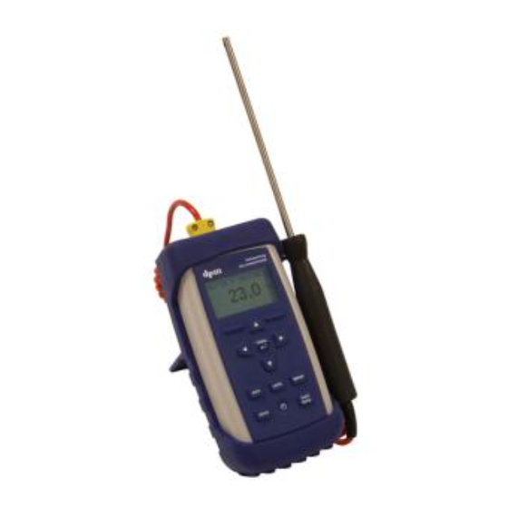
- Page 1 ST6 Series DIGITAL POCKET MANOMETER OPERATING MANUAL ...
-
Page 2: Table Of Contents
ST6 Instruction Manual CONTENTS Page 00 Limitations of Use Keypad Controls Mode of Operation Pressure Mode Display Velocity Mode Display Live Volume Display Volume Mode Display Temperature Mode Display Pressure Connections Velocity Volume Flow Rates User Menu 12 ‐ 17 Option Menu 18 ‐ 21 Conversion Tables Duct Traverse Points Downloading Data ... -
Page 3: Limitations Of Use
ST6 Instruction Manual LIMITATIONS OF USE Page 01 ST6 Series instruments are intended for measurement of low differential air pressure in and around commercial and industrial air handling systems and for use with a Pitot Static Tube, dpm Ane head, dpm Hood and dpm Short Hood. The instruments are not suitable for liquid pressure measurement and must not be used with corrosive, toxic or otherwise hazardous gases. The instruments are not classified as “Flameproof” or “Intrinsically Safe” and consequently must not be used where an explosion hazard may exist. They are also not authorised for Life Support applications. During normal operation small quantities of air (typically less than 0.1ml/min) may pass into or out of the system under test and it is the responsibility of the user to consider the consequences of such leakage before determining the suitability of the instrument for any particular purpose. The instrument must be turned off before it is stored or transported and, if it is to be stored for a long period of time or is to be transported by air, the batteries must be removed. There is a 12‐month guarantee on all manufactured parts. This guarantee does not cover any consumables, and/or wear and tear during normal or abnormal use. The guarantee becomes null and void if the instruments parts have been tampered with, misused, abused or used outside the parameters set out in this manual. The manufacturer will determine if the instrument is repairable or requires replacement; charges may apply. NOTE: RECHARGEABLE INSTRUMENTS MUST NOT BE FITTED WITH DRY CELL BATTERIES AS THIS MAY CAUSE A MALFUNCTION. ... -
Page 4: Keypad Controls
ST6 Instruction Manual KEYPAD CONTROLS Page 02 On and Off. Operate backlight. ▲ Scroll up in menu modes. Increase digits. Toggle between displays in mode of operation. (model dependent) The displays are arranged in loop formation as follows: ▲ Pressure Mode: ▲ Velocity Mode: ▲ Volume Mode: Pressure Velocity Volume Temperature Temperature Temperature Live Volume ► Scroll to the right in menu modes. Toggle between units of measurement in mode of operation. (model dependent) The units are arranged in loop formation as follows: Pa ► KPa ► mbar ► mmH O ► inH O ► mmHg ► inHg ► PSI ► m/sec ► ft/min ► ... -
Page 5: Mode Of Operation
ST6 Instruction Manual MODE OF OPERATION Page 03 Batteries Low: When the ‘battery low’ warning appears, the batteries must be replaced immediately, otherwise the readings obtained will be unreliable. If at any time the readings seem suspect, replace the batteries. For rechargeable instruments charge the internal batteries. Instrument top view: – 3 4 1: Pressure ports. The instrument responds to positive, negative and differential pressure. 2: K‐type Thermocouple. Connect a K‐type probe for temperature measurement. For temperature display see Temperature Mode Display page 08. 3: Analogue Output. Cables for the Analogue Output are supplied as an optional extra. The minimum output is 0.0 V and the maximum output is 2.5 V. The user sets the corresponding pressure in Pascals. To set pressures see User Menu page 16. Connect the white cable to the positive and the black cable to the ground. The instrument will now give voltage output corresponding to the positive pressures. 4: Mini USB port. For PC Connection used with DpmUsb Software to download data and for monitoring purposes. See Downloading Data page 24. For rechargeable instruments used with charger to charge the internal batteries. Keypad view: ... -
Page 6: Pressure Mode Display
ST6 Instruction Manual PRESSURE MODE DISPLAY Page 04 model dependent L1 Auto Zero . . . 0.0 Pa 23.3°CH Store AvPre: 36.5 S1 Speed. There are 5 different speed settings. Use the ‘speed’ key to toggle between speed settings. L1 Location number. Store data in up to nine different Locations see Option Menu page 19. The instrument will give an average value in the mode of operation for data that is stored in the same units of measurement and location. When data is downloaded to a PC it will be listed under the Location in which it is stored. Auto Zero . . . Whenever the Auto Zero sequence is initiated manually or at preset ‘Auto Zero. . .’ will be displayed until the cycle is complete. Unit of Measurement. Pa ... -
Page 7: Velocity Mode Display
ST6 Instruction Manual VELOCITY MODE DISPLAY Page 05 model dependent PT: 1.000 L1 Auto Zero . . . 0.0 m/s 23.3°CH Store AvVel: PT: 1.000 Pitot Tube Factor. Up to 5 different Pitot Tube Factors can be stored. To input Pitot Tube Factors see User Menu page 15. To select a Pitot Tube Factor see Option Menu page 20. A:1 Area Setting. Up to 5 different Area Settings can be stored. To input Area Settings see User Menu page 14. To select Area Settings see Option Menu page 19. S1 Speed. There are 5 different speed settings. Use the ‘speed’ key to toggle between speed settings. L1 Location number. Store data in up to nine different Locations see Option Menu page 19. The instrument will give an average value in the mode of operation for data that is ... -
Page 8: Live Volume Display
ST6 Instruction Manual LIVE VOLUME DISPLAY Page 06 model dependent Live Volume can only be activated when Area Settings have been stored. See User Menu page 14. To access the Live Volume Display press the ▼ key when in Velocity Mode. To return to Velocity Mode press the ▲ key. PT: 1.000 L1 Auto Zero . . . 0.0 L/s 23.3°CH Store AvVol: 47.5 PT: 1.000 Pitot Tube Factor. Up to 5 different Pitot Tube Factors can be stored. To input Pitot Tube Factors see User Menu page 15. To select a Pitot Tube Factor see Option Menu page 20. A:1 Area Setting. Up to 5 different Area Settings can be stored. To input Area Settings see User Menu page 14. To select Area Settings see Option Menu page 19. S1 Speed. ... -
Page 9: Volume Mode Display
ST6 Instruction Manual VOLUME MODE DISPLAY Page 07 model dependent +1.0/‐1.0 L1 Auto Zero . . . 0.0 sec 23.3°CH Store AvVol: +1.0/‐1.0 K Factor. Up to 4 different K Factors can be stored and a User Value can be temporarily input. To set default K Factors see User Menu page 15. To select a K Factor or to input a temporary User Value see Option Menu page 20. S1 Speed. There are 5 different speed settings. Use the ‘speed’ key to toggle between speed settings. L1 Location number. Store data in up to nine different Locations see Option Menu page 19. The instrument will give an average value in the mode of operation for data that is stored in the same units of measurement and location. When data is downloaded to a PC it will be listed under the Location in which it is stored. Auto Zero . . . Whenever the Auto Zero sequence is initiated manually or at preset ‘Auto Zero. . .’ will be displayed until the cycle is complete. ... -
Page 10: Temperature Mode Display
ST6 Instruction Manual TEMPERATURE MODE DISPLAY Page 08 To access the Temperature Mode Display press the ▲ key while in Measurement Mode. To return to Measurement Mode press the ▼ key. Display with Temperature Probe: Max: 22.8 Min: 22.3 22.5 °C Max: 22.8 Maximum Probe Reading. Min: 22.3 Minimum Probe Reading. °C Unit of Measurement Display without Temperature Probe: ‐‐‐‐‐ Default = 16°C ‐‐‐‐‐ No Probe Attached Default = Instrument Default Temperature. 16°C To change the default value, or to change the default setting from °C to °F, see User Menu page 16. To input a temporary value see Option Menu page 20. ... -
Page 11: Pressure Connections
Flow Grids: Connect +Ve tapping to + and ‐Ve tapping to –. Pressure readings should always be positive. Inlet Cones: Connect tapping to + using ‘T’ pieces to join the annular tapping together. Leave – open to atmosphere making sure that the open port is shielded against significant air movement from the ingoing airstream. Pressure readings should always be negative. Total Head Probe: Connect to +. Leave – open. Readings should always be positive dpm Ane™: Input Pitot tube factor 0.843. Connect clear tubing to + and blue tubing to –. Use the ‘units’ key to toggle to m/s or ft/min depending upon model. Readings should always be positive. dpm‐i Pitot Tube: Input the Pitot Tube factor 0.838. Connect clear tubing to + and black tubing to –. Use the ‘units’ key to toggle to m/s or ft/min depending upon model. Readings should always be positive. Ellipsoidal Pitot Tube: Input the Pitot Tube factor 1.000. Connect clear tubing to + and black tubing to –. Use the ‘units’ key to toggle to m/s or ft/min depending upon model. Readings should always be positive. ... -
Page 12: Velocity
ST6 Instruction Manual VELOCITY Page 10 dpm Ane™: Input the Pitot Tube factor 0.843. Connect the clear tubing to + and the blue tubing to –. The ane head should be placed into the air stream in the direction indicated by the arrows. Readings should always be positive. If negative readings are obtained, there may be a leak or blockage in one of the pressure tubes, the tubes may be connected the wrong way round, or the measurements may be from an extract grille. dpm‐i Pitot Tube: Input the Pitot Tube factor 0.838. Connect total pressure tapping to + and static pressure tapping to –. The larger hole located at the front of the dpm‐i Pitot Tube must face directly into the oncoming air stream. Readings should always be positive. If negative readings are obtained there may be a leak or blockage in one of the pressure tubes or the tubes may be connected the wrong way round. Ellipsoidal Pitot Tube: Connect total pressure tapping to + and static pressure tapping to –. The hole at the tip of the Pitot Static Tube must face directly into the oncoming air stream. Readings should always be positive. If negative readings are obtained, there may be a leak or blockage in one of the pressure tubes or the tubes may be connected the wrong way round. Most Pitot Static Tubes will give satisfactory results, but the NPL modified ellipsoidal pattern is particularly recommended. The velocity range is calibrated at ‘standard air’ 1000 mbar / 16°C, for use with Total Head Probes and Pitot Static Tubes having a calibration factor unity. For non‐standard air‐conditions the barometric pressure and temperature can be set via the User Menu, see page 16 or the Option Menu, see page 20. Air Velocity Calculations using S.I Scales: For non‐standard air conditions: V = 1.291 x PT 1 013.25 x T x Pv ... -
Page 13: Volume Flow Rates
ST6 Instruction Manual VOLUME FLOW RATES Page 11 model dependent First Method: Select the duct shape and input the duct dimensions in millimetres or inches. When data is stored in m/s or ft/min the Velocity Display shows the average velocity; in the Live Volume Display, this value is multiplied by the area to give the average volume. To access the Live Volume Display press the ▼ key when in Velocity Mode. To return to Velocity Mode press the ▲ key. PT: 1.000 L1 Auto Zero . . . L/s 23.3°CH Store AvVol: 47.5 AvVol: Average Volume of the stored readings. The Average Volume a function on Velocity multiplied by Area. Second Method: K Factor: The principle of calculation is to measure the differential pressure across the device, square root this value then multiply by the K Factor. The result is in m³/hr. The K Factor is printed or obtained from the device manufacturer. Alternatively, to determine the K Factor value: K = (m³/hr) / (√Pd). ‐ Connect the +Ve tapping to and the ‐Ve tapping to ... -
Page 14: User Menu 12
A manual zeroing facility is available see Keypad Controls page 02. Switch Off Period: To save battery the instrument is factory set to switch off after 10 minutes. This can be overridden by changing the default setting. Backlight Period: To increase or decrease the backlight time. Page 14 Area Settings: (model dependent) Select either inches or millimetres and input the duct shape and dimension. Store up to 4 different Area Settings. Note: If duct dimensions are input in inches, the instrument converts to millimetres in order to calculate the area, which is then converted into square feet. This is the area shown in Review Results. Page 15 Pitot Tube Factor: (model dependent) Store up to 4 Pitot Tube factors and the dpm Ane factor. K Factor (model dependent) Store up to 2 different K factors and the dpm Hood factors. Page 16 Temperature: Select a temperature unit and input a user temperature. Barometer: Select a barometer unit and input the barometric pressure. Analogue Output: Input the maximum and minimum output. Page 17 Vel / Vol Readings: (model dependent) Select the decimal places for velocity and volume readings. ... - Page 15 ST6 Instruction Manual USER MENU Page 13 Selecting from a list: menu Use ▲ and ▼ to scroll. Press to select. Entering a value: Use ▲ and ▼ to set each digit. Use ► to move on the next digit. menu Press to confirm. Set Clock AutoZero Period Auto Zero Time 060 Seconds Switch Off Period Max Setting: 600 menu Press Backlight Period Min Setting: 010 Area Settings To switch off input: 000 Pitot Tube Factor ...
- Page 16 ST6 Instruction Manual USER MENU Page 14 Selecting from a list: menu Use ▲ and ▼ to scroll. Press to select. Entering a value: Use ▲ and ▼ to set each digit. Use ► to move on the next digit. menu Press to confirm. Set Clock Select Unit Auto Zero Time Switch Off Period Backlight Period Exit Area Settings Select Entry Pitot Tube Factor 0 Dia. menu Press K Factor ...
- Page 17 Page 15 Selecting from a list: menu Use ▲ and ▼ to scroll. Press to select. Entering a value: Use ▲ and ▼ to set each digit. Use ► to move on the next digit. menu Press to confirm. Set Clock Select Entry Auto Zero Time dpm A: 0.843 Switch Off Period 0.000 Backlight Period 0.000 Area Settings 0.000 Pitot Tube Factor 0.000 K Factor Exit menu Press ...
- Page 18 ST6 Instruction Manual USER MENU Page 16 Selecting from a list: menu Use ▲ and ▼ to scroll. Press to select. Entering a value: Use ▲ and ▼ to set each digit. Use ► to move on the next digit. menu Press to confirm. Set Clock Select Temperature Units Auto Zero Time Centigrade Switch Off Period Fahrenheit Backlight Period Exit Area Settings Set Temperature Pitot Tube Factor 000°C K Factor Max Setting: 999°C / 1830°F ...
- Page 19 ST6 Instruction Manual USER MENU Page 17 Selecting from a list: menu Use ▲ and ▼ to scroll. Press to select. Entering a value: Use ▲ and ▼ to set each digit. Use ► to move on the next digit. menu Press to confirm. Set Clock Vel / Vol Reading Auto Zero Time Decimal Switch Off Period Points = Backlight Period Max Setting: Area Settings Min Setting: Pitot Tube Factor User Menu K Factor Temperature ...
-
Page 20: Option Menu 18
ST6 Instruction Manual OPTION MENU Page 18 The Option Menu is to temporarily change default settings. Any settings changed in the Option Menu will be lost as soon as the instrument is switched off. menu To access the Option Menu, press when the instrument is in operation mode. Page 18: Review Results: View stored data in the form of time, measured value and unit of measurement. Use the ► key to view further data on individual values. Note: In Review Results, when ‘mix units’ is shown this indicates a change of Location or units. Page 19: Del Last Result: Deletes the last stored value. Clear Memory: Deletes all stored data. Set Location: Select a location in which to store data. The instrument will give an average value in the mode of operation only for data that is stored in the same Units of Measurement and Location. When data is downloaded to a PC it will be listed under the location in which it is stored. Select Area: (model dependent) Select an area setting from a list of defaults. Page 20 Select P Factor: (model dependent) Select a Pitot Tube factor from a list of defaults. Select K Factor: (model dependent) Select a K factor from a list of defaults or input a User Value. Set Temperature: ... - Page 21 ST6 Instruction Manual OPTION MENU Page 19 Selecting from a list: menu Use ▲ and ▼ to scroll. Press to select. Entering a value: Use ▲ and ▼ to set each digit. Use ► to move on the next digit. menu Press to confirm. Review Results Delete Last Result Del Last Result Done Clear Memory To return to Option Menu menu Press Set Location menu press Select Area Select P Factor Select K Factor ...
- Page 22 Page 20 Selecting from a list: menu Use ▲ and ▼ to scroll. Press to select. Entering a value: Use ▲ and ▼ to set each digit. Use ► to move on the next digit. menu Press to confirm. Review Results Select Pitot Factor Del Last Result dpm A: 0.843 Clear Memory 1.000 Set Location 1.000 Select Area 1.000 Select P Factor 1.000 Select K Factor Exit menu Press ...
- Page 23 ST6 Instruction Manual OPTION MENU Page 21 Selecting from a list: menu Use ▲ and ▼ to scroll. Press to select. Entering a value: Use ▲ and ▼ to set each digit. Use ► to move on the next digit. menu Press to confirm. Review Results Barometric Pressure: Del Last Result 1000 mbar Clear Memory Max Setting: 1200 mbar / Set Location 35.50 inHg Select Area Min Setting: 800 mbar / 23.60 inHg Select P Factor Select K Factor Option Menu ...
-
Page 24: Conversion Tables
ST6 Instruction Manual CONVERSION TABLES Page 22 Pressure: Pa mbar O mmHg inHg Pa 1 100.0 9.806 249.1 133.3 3385 6892 mbar 0.010 0.098 2.491 1.333 33.85 68.92 O 0.102 10.20 25.40 13.60 345.42 702.8 O 0.004 0.402 0.039 0.535 13.51... -
Page 25: Duct Traverse Points
ST6 Instruction Manual DUCT TRAVERSE POINTS Page 23 Principle of Operation: Pitot Head The nose of the Pitot Tube should face directly into the airstream thus the Total Pressure flows down the inner tube which is connected to the Signal In port. The static holes are positioned around the side of the Pitot Tube and lead into an outer tube. This is connected to the black Velocity Pressure* = Total Pressure – Static Pressure tubing which in turn is connected to the Reference port. Calculated by the digital pocket manometer Log Linear Rule for Traverse Points on 3 Diameters in a Circular Duct: Ideally traverse points should be at least six duct diameters away from any bend or obstruction in the system. The Pitot Tube should be inserted at right angles to the walls of the ducts and measurements are taken in the positions shown in the diagrams (left). The directional pointer can be used to ensure that the Pitot Tube head is parallel to the duct walls. 0.032D 0.135D 0.321D 0.679D 0.865D 0.968D ... -
Page 26: Downloading Data
New’. A progress bar will appear on the screen followed by a message that reads ‘All data successfully loaded. Erase from the Unit?’ It is recommended to click ‘No’. The cable can be disconnected from the instrument. The data is stored now stored on the PC under the same Location number(s) as it is stored on the instrument. The data is non‐editable. Export Data: Click ‘File’ on the toolbar at the top of the screen. Under ‘File’ click ‘Export csv file’. Give the file a name and check where it will be saved then click ‘Save’. Open the file in Excel. Further information on the DpmUsb software can be found in the software help file. Maintenance: There are no user serviceable parts in the digital pocket manometer. With the exception of dry cell batteries there are no consumable parts. If the instrument is damaged or requires servicing it should be returned to the Buckingham England factory. Calibration: All ST6 instruments are calibrated against equipment traceable to National Standards. It is good practice to have the instrument calibrated and checked at least once a year. The Buckingham England factory offers a calibration service; see address below. In the interest of continuous product development and improvement DP Measurement reserve the right to amend specifications and to discontinue models, features and colours of the ST6 Series Micromanometers at any time without prior notice Manufactured in UK DP Measurement Unit 11, Top Angel, Buckingham Industrial Park Buckingham, England. MK18 1TH Tel / Fax: +44 (0)1280 817122 www.ttseries.com email: dpm@ttseries.com ... -
Page 27: Specifications
± 10.0 to 99.9 ± 100 to 510 O ± 0.000 to 0.999 ± 1.00 to 9.99 ± 10.0 to 20.0 mmHg ± 0.000 to 0.999 ± 10.00 to 37.51 inHg ± 0.000 to 0.999 ± 1.00 to 1.47 ± 0.000 to 0.726 Velocity: dpm Ane head dpm – i Pitot Tube Ellipsoidal Pitot Tube m/sec 0.70 to 25.0 0.70 to 90.0 0.70 to 90.0 ft/min 138 to 4921 138 to 17730 138 to 17730 Volume (Hood mode): Plate A Plate B L/sec Supply / Exhaust 13.0 to 100 35.0 to 555 /hr Supply / Exhaust 45.0 to 360 127 to 1998... - Page 28 Dimensions: 145 x 85 x 50 mm with holster Standard Accessories: 2mm x 6mm tubing adaptors (4) Instruction manual 3m x 2mm bore flexible tubing (2) Rubber holster Calibration certificate Soft lined case Optional Extras: Analogue Output DpmUsb software TM dpm ane Pitot Static Tubes TM dpm Hood Temperature Probes dpm Short Hood USB cable Calibration certificate is traceable to National Standards. In the interest of continuous product development and improvement DP Measurement reserve the right to amend specifications and to discontinue models, features and colours of the ST6 Series Micromanometers at any time Manufactured in UK without prior notice. DP Measurement ...
Need help?
Do you have a question about the ST6 Series and is the answer not in the manual?
Questions and answers