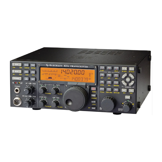
ELECRAFT K3S Owner's Manual
High-performance
160 – 6 meter transceiver
Hide thumbs
Also See for K3S:
- Assembly manual (92 pages) ,
- Kit assembly and instruction manual (91 pages) ,
- Programmer's reference manual (33 pages)

Related Manuals for ELECRAFT K3S


Summary of Contents for ELECRAFT K3S
- Page 1 LECRAFT ® ERFORMANCE 160 – 6 M ETER RANSCEIVER ’ WNER ANUAL Revision A1, May 26, 2015 Copyright © 2015, Elecraft, Inc. All Rights Reserved...
-
Page 2: Table Of Contents
Specifications ............8 Preamp 2 Limitations ........45 Customer Service and Support ......10 Remote Control of the K3S ......46 Front Panel ............. 11 Options and Accessories ........ 47 Control Groups ..........11 Firmware Upgrades ........47 ... -
Page 3: A Note To K3 S Owners
A Note to K3 Owners On behalf of our entire design team, we’d like to thank you for choosing the Elecraft K3 transceiver. The K3 is the same size and weight (~9 lbs.) as its predecessor, the K3. Yet nearly all internal modules have been redesigned, providing enhanced performance and many new features. -
Page 4: Quick-Start Guide
Quick-Start Guide To get started using your K3 right away, please read this page and the two that follow, trying each of the controls. The text uses braces to refer to numbered elements in the front- and rear-panel illustrations below. For example, {1} in the text refers to . - Page 5 Connections Connect a power supply to the DC input jack {26} (see Specifications, pg. 8). • On the K3 /100, a circuit breaker is provided on the fan panel for the 100-W stage {39}. • You can power an accessory device from the switched DC output jack {40} (1.0 A max). •...
- Page 6 VFOs {21} selects 10 or 50 Hz VFO/RIT tuning. See VFO menu entries, pg. 57. R A T E • and RIT/XIT {21} selects 1-Hz steps. selects large steps (MAIN menu, VFO CRS). F I N E C O A R S E •...
-
Page 7: Introduction
Introduction This comprehensive manual covers all the features APF (audio peaking filter) for digging out • and capabilities of the Elecraft K3 transceiver. We weak signals in CW mode (pg. 32) recommend that you begin with the Quick-Start Internal CW-to-RTTY or CW-to- •... -
Page 8: Specifications
Specifications Some specifications apply only if the corresponding option modules are installed (see Options, pg. 47). GENERAL Frequency Range Main and Sub Receivers: 100 kHz - 30 MHz and 44-54 MHz (see receiver Sensitivity spec). Transmitter: Amateur bands between 1.8 and 54 MHz (limits vary by country). 144-148 MHz with K144XV option. - Page 9 IF Shift/Width & Lo/High Cut with automatic crystal filter selection * Receive specifications are guaranteed only within ham bands. Dynamic range measurements based on 400-Hz, 8-pole filter. See www.elecraft.com for full list of available crystal filters. TRANSMITTER * Output Power /100: 0.1 W –100 W typ.
-
Page 10: Customer Service And Support
Elecraft products transferred by the purchaser to a third party, either by sale, gift, or other method, who is not disclosed to Elecraft at the time of original order, are not covered by this warranty. If the Elecraft product is being bought indirectly for a third party, the third party’s name and address must be provided at time of order to ensure... -
Page 11: Front Panel
Front Panel This reference section describes all front panel controls, the liquid crystal display (LCD), LEDs, and connectors. Operating instructions are covered in later sections. Control Groups Primary Controls (pg. 13): These controls Keypad (pg. 15): This group of switches is provide basic transceiver setup, including power numbered for use during memory store/recall and on/off, band, operating mode, AF and RF gain and... -
Page 12: Display (Lcd)
Display (LCD) Multi-character displays: The 7-segment display VFO Icons: The icon indicates which VFO is (upper) shows the VFO A frequency. The 13- selected for transmit. In TX TEST mode, or when segment display (lower) shows VFO B or text. TX is inhibited externally, flashes (see T E S T... -
Page 13: Leds
D A T A R E V A M - S mode, selects or simplex (pg. 31). MIC An Elecraft MH2, MD2, Proset-K2, or other compatible mic can be used (see pinout below). To Selects TX TEST ( LCD icon flashing);... -
Page 14: Multi-Function Controls
Dual-Concentric Potentiometers Transmit Controls — AF gain controls for main The primary functions of the transmit controls are: receiver (inner, or smaller knob) and sub receiver Keyer speed in WPM, 8-50 (8-100 S P E E D (outer ring, or larger knob). if CONFIG:CW QRQ is —... -
Page 15: Keypad
Direct Frequency Entry Receiver Control & Misc. (Lower Rows) To jump to any frequency within the tuning range Receiver control functions normally apply to of the K3, tap , then enter 1 to 3 MHz F R E Q E N T VFO A/main receiver. -
Page 16: Memory Controls
B display; “*” appears if you’re within the most to 5 characters (A-Z, 0-9, and various symbols). recent segment. Use VFO B to change the position. The Elecraft Frequency Memory Editor For DVR voice message record/play, see pg. 31. software application can be used to simplify setup and use of memories. -
Page 17: Rear Panel
(pg. 41), a buffered I.F. output for ANT3 (BNC, on the KPA3A option panel) is the use with the Elecraft P3 (pg. 47), and internal I.F. antenna jack for the optional K144XV 2-m module. connections for the K144XV 2-m module. Preamp... -
Page 18: Control And Audio Connections
If you also have a P3, connect it to the • USB Port (Control and Audio) RS232/P3 port as shown, using an Elecraft model CBLP3Y cable. The USB port can be used for computer-based remote control. It also acts as the equivalent of a Set the CONFIG:RS232 menu parameter to •... - Page 19 To connect a P3 Panadapter to the K3 , and optionally connect a computer to the P3 (via The RS232/P3 port can be used with an Elecraft P3 RS232): Panadapter, or with a computer’s RS232 interface. Use the supplied Elecraft #E980297 cable to •...
- Page 20 RS232 Adapter Cable ACC (Accessory I/O) The supplied Elecraft #E970297 cable converts ACC connector pinouts are listed below. from RJ45 (at the K3 end) to DE9 (RS232 standard). The DE9 end can be connected to a P3’s ACC is not a VGA video connector. The K3 XVTR jack, or to a computer’s RS232 port.
- Page 21 Elecraft KRC2 Universal Band Decoder accessory via the AUXBUS line. Note: T R N 1 - 7 An Elecraft KRC2 can be used with the K3 to are sent as 1-7, but are sent as 0. T R N 8 - T R N 9 perform station switching functions;...
- Page 22 LINE OUT level, and can also worsen noise very low-output mics. Not required for use with pickup. If a high-impedance mic input must be the Elecraft MH2. used, you can add a resistive attenuator between the If the rear-panel mic has a PTT line, it can be...
-
Page 23: Basic Operation
Basic Operation MAIN Menu to access the main menu. (Tapping • M E N U This section covers the fundamentals of K3 again exits the menu.) M E N U receive and transmit operation. It’ll also get you Use VFO B to scroll through the menu entries, •... - Page 24 Band and Mode Selection Using the VFOs Tap either end of to select the desired ham VFO A is both the main receive and transmit B A N D band (160 through 6 meters). You can use direct frequency, except during SPLIT, in which case frequency entry (pg.
-
Page 25: Receiver Setup
Receiver Setup Filter Passband Controls This section explains how to use basic receiver As you rotate the filter controls (shift, width, lo cut, controls. Setup for specific operating modes is hi cut), the associated parameter value is shown on described in later sections; see Voice Modes (pg. VFO B. - Page 26 Filter Presets (I/II) Custom Settings (NORM1 and NORM2) In addition to the standard "NORM" values, you Each operating mode provides two “floating” filter can save two of your own setups in each mode, then presets, I and II, which store filter settings on a recall them using the function.
-
Page 27: Reducing Interference And Noise
Reducing Interference and Noise The DSP noise blanker is in the 2 I.F., where it can’t be activated by signals outside the crystal The K3 provides several ways to cut interference, including DSP noise reduction, manual and auto filter passband. It can be used with high-duty-cycle notch, and noise blanking. -
Page 28: Transmitter Setup
Transmitter Setup VOX, PTT, and QSK Transmit Crystal Filter Considerations In voice and data modes, use to select VOX V O X (pg. 13) or PTT (push-to-talk). PTT can still be For each operating mode, you must specify which used even with VOX selected. Set VOX gain and I.F. - Page 29 External ALC Per-Band Power Control If the CONFIG:PWR SET menu parameter is set External ALC should only be used to protect , output on all HF bands follows the present your amplifier during operation into a failed N O R setting of .
-
Page 30: Voice Modes (Ssb, Am, Fm)
) jack, low or high mic gain range, and bias voltage for electret microphones. The front-panel mic jack is compatible with the • Elecraft MH2, MD2, Proset-K2, and some other 8- Adjust for the desired speech C M P •... - Page 31 Voice Mode VOX Setup Transmit Noise Gate selects push-to-talk (PTT) or voice-operated The noise gate function mutes mic audio below a V O X (VOX) transmit ( icon on). VOX hold time is selected threshold; this may be useful in noisy V O X set with (pg 14).
-
Page 32: Cw Mode
SPOT and Auto-Spot CW Mode When calling another station, you should try to CW Normal and Reverse match your frequency to theirs. To facilitate this, Select CW mode by tapping either end of the K3 provides both manual and automatic M O D E spotting for use with CW and DATA signals. -
Page 33: Data Modes
“TT1;” (text-to-terminal). “TT0;” modes, multiple data speeds are available; select turns it off. See the K3/KX3 Programmer’s them by rotating VFO A. Reference, available at www.elecraft.com. Also shown is the current sideband ( L S B U S B Data Mode Selection If this sideband is considered “data reverse”... - Page 34 AMTOR / PacTOR RTTY Dual-Tone Filter (DTF) AMTOR, PacTOR and similar modes can reliably Hold to turn on the RTTY dual-tone filter A P F transfer data – including e-mail – via HF radio (DTF). This creates two filters, one centered on the networks.
-
Page 35: Advanced Operating Features
Advanced Operating Features Text Decode And Display DATA Text Decode Setup The K3 can decode CW, PSK31 or PSK63, and To set up text decode for DATA modes: RTTY. Decoded text is displayed on VFO B. In to DATA. Then hold M O D E D A T A M D •... -
Page 36: Cw-To-Data
CW-to-DATA Tuning Aids: CWT and SPOT You can use data modes completely stand-alone Tapping turns the upper half of the S-meter C W T (i.e., without a computer). Just turn on text decode into a CW/DATA tuning aid. If no bar appears in (pg. -
Page 37: Audio Effects (Afx)
Audio Effects (AFX) Receive Audio Equalization (EQ) If you have stereo headphones or stereo external The K3 provides 8 bands of receive audio speakers, you can take advantage of the DSP’s equalization via the MAIN:RX EQ menu entry. RX audio effects. These create an illusion of greater EQ can compensate for the physical acoustics of acoustic space. -
Page 38: Split And Cross-Mode Operation
General-Coverage Receive SPLIT and Cross-Mode Operation Normally, VFO A is used for both receive and The KBPF3A option includes band-pass filters that transmit. When mode is selected, VFO B cover the areas between ham bands. The K3 will S P L I T becomes the transmit VFO. -
Page 39: Using The Sub Receiver
Using the Sub Receiver The sub receiver’s band cannot be set independently unless CONFIG:VFO IND is set to The KRX3A option adds an independent, high- Y E S . If it’s set to N O , you’ll see = M A IN when during B S E T , and the sub receiver performance sub receiver to the . - Page 40 8-pole filters are already matched (FLx matches the sub’s filter bandwidth to main, and FRQ = 0.00). Elecraft can provide pairs of 5-pole switches the sub receiver to its AUX antenna. The crystal filters with offsets within 40 Hz of each kHz decimal point of the VFO A display flashes as other on request.
-
Page 41: Receive Antenna In/Out
Receive Antenna In/Out Using Transverters The RX ANT IN/OUT jacks have various uses: Nine user-definable bands are provided for use with transverters. These can be used with the Elecraft Low-noise receiving antenna: Connect a • K144XV internal 2-m module, Elecraft XV-Series, Beverage or tuned loop to the RX ANT IN jack, or other transverters. -
Page 42: Scanning
(6- used on any band. meter scanning range is limited to 50-54 MHz by default; contact Elecraft for details.) The U.S. 60-meter USB channel assignments correspond to K3 VFO settings of 5330.5, 5346.5, Scanning while muted (normal scanning mode) 5357.0, 5371.5, and 5403.5 kHz. -
Page 43: Main And Sub Receiver Antenna Routing
Main and Sub Receiver Antenna Routing The simplified block diagrams in this section show how antennas are routed to the main and sub receivers. Heavy lines show the default RF path. All antennas are protected from electrostatic discharge by surge arrestors. Receive-only antenna inputs, indicated by asterisks (*), include carrier-operated relay circuitry (C.O.R.). - Page 44 RX Ant. Includes C.O.R. KXV3 KANT3 Main RX Ant. Input Module Ant 1 KRX3 Aux RF Sub RX Figure 2. Main/Sub Receiver Routing Including RX ANT IN on KXV3B Module KAT3A ATU and Antenna 2 The KAT3A internal ATU option, which can be installed in place of the KANT3 antenna input module, provides a second SO-239 antenna jack (ANT 2).
-
Page 45: Preamp 2 Limitations
Figure 4 shows the antenna possibilities when both the KAT3A and KXV3B are taken into consideration. The main receiver can use ANT 1, 2, or RX ANT IN. The sub receiver can either share the main receiver’s RF source or use its AUX RF input. The sub’s AUX signal can be obtained from either the non-transmit KAT3A antenna or the AUX RF BNC connector, as described earlier. -
Page 46: Remote Control Of The K3S
Frequency memories can be easily viewed and split mode, assign VFO A to B, move VFO B up 5, changed using our Elecraft Frequency Memory and turn on diversity receive. Refer to K3 Utility Editor application. This program shows the help or the Programmer’s Reference for examples. -
Page 47: Options And Accessories
Upgrades may level control (see CONFIG:PWR SET). Same size also be required when you install option modules. and styling as the K3 Please visit the Elecraft K3/K3 software page KAT500: 500 Watt+, wide-range ATU. The K3 (www.elecraft.com/K3/k3_software.htm) to obtain can be configured to update the KAT500 as the our free firmware download application, K3 Utility. -
Page 48: Configuration
Configuration Adjust VFO A so that the parameter matches • FL1’s marked frequency offset (as recorded in the filter information table, Appendix A). The Configuring the K3 involves installing modules default value, , corresponds to the nominal 0 . 0 0 and filters, then customizing menu settings. -
Page 49: Module Enables
Transmit Crystal Filter Selection (Per-Mode) KBPF3A general-coverage band-pass filter • module: set KBPF3A to (if you’re N O R This step applies only to filters on the RF board. installing a KBPF3A on the sub receiver, first in the menu entry). S U B Select CW mode by tapping M O D E... -
Page 50: Miscellaneous Setup
See pg. further details, refer to the K3/0-Mini manual. 13 for Elecraft mic bias recommendations. Tap boost gain for very low-output front panel mics. VFO A Knob Friction Adjustment AF Gain Range The VFO A knob’s spin rate can be adjusted by... -
Page 51: Vfo B Knob Friction Adjustment
VFO B Knob Friction Adjustment Use the supplied 5/64" (2 mm) Allen wrench to loosen the VFO B knob’s set screw. Between the knob and front panel is a felt washer which, when compressed, reduces the spin rate. Move the knob in or out in small increments until the desired rate is obtained, re-tightening the set screw each time. -
Page 52: Calibration Procedures
Milliwatt-meter Calibration (XVTR OUT) Calibration Procedures Set the CONFIG:KXV3B menu entry to • All calibration procedures are firmware- , forcing all bands to temporarily use the T E S T based. Please do not adjust any of the trimmer KXV3B’s transverter output jack. Power will capacitors or potentiometers inside the K3 be limited to 1.5 mW. -
Page 53: Reference Oscillator
High Power (50 W) TX Gain Calibration Before attempting to calibrate the reference oscillator using Method 1 or 2, allow the This applies to the K3 /100 only. Use the same transceiver to warm up at room temperature for procedure as shown for 5 watts, but set power to 50 at least 15 minutes (cover on). -
Page 54: Front Panel Temperature Sensor
SC change, re-adjust the SMTR OF setting for signal source (an accurate signal generator such as an S-9 indication. an Elecraft XG2 or XG3 can be used). When you have completed this procedure, • Switch to a band applicable to your signal •... -
Page 55: Menu Functions
Menu Functions Save your configuration using K3 Utility after changing menu settings. There are two groups of menu functions: MAIN and CONFIG. Each group is ordered alphanumerically. MAIN menu entries are shown below. CONFIG entries, which are used for initial configuration and advanced features, start on page 57. - Page 56 RX EQ +0 dB, Receiver audio graphic equalizer. VFO A is used as an 8-band bar graph, showing each boost or cut dB to dB in 1 dB increments) for each AF band. ( - 1 6 + 1 6 band The 8 bands are 0.05, 0.1, 0.2, 0.4, 0.8, 1.6, 2.4 and 3.2 kHz.
-
Page 57: Config Menu
CONFIG Menu Save your configuration using K3 Utility after changing menu settings. Tech Mode Entries Menu entries that include [T] are tech mode entries. These are only visible if CONFIG:TECH MD is set to They are normally left at their defaults. Entries described as “Advanced” or “Troubleshooting” should be changed with caution. - Page 58 If set to , a 400-Hz transmit audio filter is added (via DSP) in order to AFSK TX FIL OFF F I L O N maximize transmit signal to noise ratio. This may be useful in high-noise computer environments. Applies only to AFSK-A mode (RTTY). (Advanced) Integration time for displays in ms.
- Page 59 (8215.0 kHz). Use the offset F L x value specified on the crystal filter’s label or PC board, if any. For example, if an Elecraft 5-pole, 200-Hz filter were labeled “-0.91”, adjust VFO A for – 0 . 9 1 0 dB Crystal filter loss compensation in dB.
- Page 60 If the menu entry name is (without the ), then the K3 has not correctly K I O 3 detected the KIO3B module, and the USB and RS232 ports will not function. Try turning power off/on. If the problem persists, contact Elecraft.
- Page 61 KPA3 Not Inst Set to if KPA3A 100-W amp installed. Set to if KPA3A is P A N O R P A I O O N not installed, but the KPAIO3A transition PC board is. Other settings include (disables PA if installed), PA fan test settings ( B Y P P A F N 1 F N 4...
- Page 62 Set to if your mic has UP/DOWN buttons compatible with the front-panel mic jack. Not applicable to the Elecraft MH2 or MD2 microphones. Tapping UP/DOWN once moves the VFO up/down one step (based on current tuning rate); holding UP/DOWN moves up/down continuously. If frequency moves up/down continuously, your mic is not compatible;...
- Page 63 PTT RLS (Advanced) Provides a delay between release of PTT and dropping of the transmit carrier; intended for use with fast turn-around data protocols such as AMTOR and PacTOR. (No effect in CW, FSK D, or PSK D modes.) A value of 20 or higher may be needed to ensure accurate data transmission with these protocols.
- Page 64 (Advanced; Optional) SIG RMV can be used to remove fast-tuning carrier SIG RMV [T] signals (spurs or “birdies”) that are audible even with an antenna connected. Limitations: Applies only to CW/SSB/DATA modes, and only to the main receiver. In CW and DATA modes, SIG RMV should not be used in combination with a CONFIG:PB CTRL setting of .
- Page 65 SQ MAIN This menu entry normally sets the main receiver squelch value ( ). If VFO A is rotated fully clockwise, the parameter changes to . Squelch for = S U B P O T both main and sub receivers will then be controlled by the SUB RF/SQL knob, and both main and sub RF gain will be controlled by the MAIN RF/SQL knob.
- Page 66 TUN PWR If set to power level follows the POWER knob. Otherwise, N O R T U N E establishes a fixed power level for , overriding the present POWER knob T U N E setting. Note1: TUN PWR does not pertain to , which always uses 5 A T U T U N E or 10 W and is internally controlled.
- Page 67 TXGN{pwr} (Troubleshooting) Shows transmit gain constant for the present band and power mode, where {pwr} = (0-12W), (13-120W), or (0.1-1.5 mW). The gain constant is updated whenever the function is activated on a given T U N E band at one of three specific power levels: 5.0 W, 50 W, and 1.00 milliwatt. See transmit gain calibration procedure, pg.
- Page 68 Elecraft XV- T R N 1 T R N 7 series transverters and the Elecraft KRC2 band decoder, so they are sent on the “AUXBUS” serial control line (TRN8 and TRN9 are sent as 0 on the auxBus). –...
-
Page 69: Troubleshooting
Most problems are related to firmware or control settings. Subsequent sections cover Parameter Initialization (pg. 72) and Module Troubleshooting (pg. 73). If the problem persists, please contact Elecraft support (see pg. 10) or post a question on our email reflector. - Page 70 A L C O F F • turned off during band-pass filter alignment (do not adjust filters without consulting Elecraft support). Can’t transmit in CW mode: (1) Make sure the key or keyer paddle is plugged into the correct jack.
- Page 71 12, 10, or 6 meters, then the K3 has not recognized the correct RF board type. Try turning power off/on. If the problem persists, contact Elecraft. (4) Make sure the CONFIG:KXV3B menu entry name is , not .
-
Page 72: Parameter Initialization
Parameter Initialization Menu parameters are stored in non-volatile memory (EEPROM and/or FLASH). It is possible, though rare, for parameters to become altered in such a way as to prevent the firmware from running correctly. If you suspect this, you can reinitialize parameters to defaults, then restore a previously-saved configuration (or re-do all configuration steps manually;... -
Page 73: Module Troubleshooting
DO NOT ADJUST ANY TRIMMER CAPACITORS OR POTENTIOMETERS unless you have access to appropriate lab test equipment and have consulted Elecraft support regarding the proper settings. All trimmers have been aligned at the factory, and if misadjusted could degrade performance. - Page 74 ERR DSG DSP internal gain error Turn K3 off and back on to clear the error condition. Please report this to Elecraft, along with DSP internal error information. (In the TECH MD menu entry, tap to get main/aux DSP info, respectively.)
- Page 75 (pg. 72). ERR IF1 RF board IF shift registers not responding Try turning power off/on. If the problem persists, contact Elecraft. ERR IF2 Sub RX IF shift registers not responding Try turning power off/on. If the problem persists, contact Elecraft.
- Page 76 This usually indicates a problem with band-pass filter alignment or one of the low-pass filters. In either case it could affect one or two bands. Consult Elecraft support before attempting to realign band- pass filters; all settings are aligned at the factory.
-
Page 77: Theory Of Operation
Schematics and additional details can be found on the Elecraft web site. Only basic modules are covered here; for option module circuit details, refer to the individual instruction manuals (KPA3A, KBPF3A, KRX3A, etc.). - Page 78 General coverage receive capability can be added to the K3 with the KBPF3A option, which includes another 8 band-pass filters that cover all of the areas from 100 kHz to 28 MHz that are not covered by the filters on the RF board.
-
Page 79: Kat3A (Atu) And Kant3
RS232 communications and/or the P3 panadapter, and a DE-15 accessory connector for external band decoders (such as the KRC2), transverters (such as the Elecraft XV series), and similar devices. The DE-15 is also used for direct FSK or PSK signaling. - Page 80 Front Panel Board This board provides the transceiver’s user interface: 35 custom-labeled switches; two dual-concentric potentiometers for gain and squelch control; seven shaft encoders; custom, 240-segment, high-contrast LCD; and 13 discrete LED indicators. Mic and headphones can be plugged into the front panel, or optionally at the rear panel (see KIO3B description, pg.
-
Page 81: Kref3 (Ref./2 Ksyn3A (Synthesizer)
The DSP board is piggybacked onto the Front Panel board as part of the Front Panel assembly. The Auxiliary DSP (used if the KRX3A Second Receiver Option is installed) and the KDVR3 option plug into the DSP board. KREF3 (Ref./2 The KREF3 module’s 49.380-MHz temperature-compensated crystal oscillator (TCXO) is the signal source for the synthesizers. - Page 82 Transmit ALC and Per-Band Power Control To eliminate transmit splatter, all ALC in the K3 is applied before the narrow first-I.F. crystal filter. However, with some vocalizations, speech energy may build up within a narrow crystal filter to produce a slight peaking effect.
-
Page 83: K3 S Block Diagram
Block Diagram... -
Page 84: Appendix A: Crystal Filter Installation
(ESD) can occur if you don’t take proper precautions. Such damage is not covered by the Elecraft warranty, and could result in costly repairs. We recommend that you use an anti-static mat and wear a conductive wrist strap with a series 1-megohm resistor. - Page 85 Locate the crystal filters you presently have installed in slots FL1 - FL5 on the RF board (or sub receiver). There may be a mix of 5-pole filters (below left) and 8-pole filters (right). Review the information below to ensure that your crystal filter setup conforms to K3 requirements.
- Page 86 Fill in the table below (include sub receiver info, if applicable). Use pencil, since you may change the configuration later. can be obtained from the model number of each filter. 5-pole filters have a B A N D W I D T H marked on the side of one of the crystals, e.g.
- Page 87 Turn the K3 right side up. Unplug all filters to be repositioned (those whose mounting screws have been removed). Lift the filters at each end carefully, first one end then the other, until the connectors separate. Reposition the filters as required. They will only fit one way. If you put one in backwards, it will not fit within its outline, and the standoff will not line up with the screw hole in the RF board (or sub receiver board).
-
Page 88: Index
Index 12 VDC IN, 17 Circuit Breaker, 17, 74 12 VDC OUT, 17 Clock/Calendar, 65 1-Hz Tuning, 24 Compression, 14, 28, 30 Accessory 12 VDC Output, 17 CONFIG Menu, 23, 48, 55, 57, 65 Accessory I/O (ACC), 20 Configuration, 7, 48, 72 AF Balance Control, 39, 65 Connector Groups, 17 AF Gain Range, 57... - Page 89 FM Deviation, 60 LPA, 77 FM Mode, 13, 30, 31 M1-M4, 6, 11, 16, 31, 32 FP ACC, 13 Macros, 23, 46 Frequency Entry, Direct, 15 MAIN Menu, 23, 55 Frequency Memories, 16 Memories, 16, 62 Frequency Range, 8, 42 Memory Label, 16, 42 Friction Adjustment, VFO Knob, 50, 51 Menu Help, 23...
- Page 90 RF Board, 77 Synthesizer, 38, 52, 74, 78, 79, 81, 83 RF GAIN, 54 Tap/Hold Switch Functions, 11, 23 RFI Detection, 63 TCXO, 8, 34, 47, 53, 81 RIT, 6, 11, 14, 16, 24, 67 Tech Mode Menu Entries, 65 RIT/XIT Offset, 7, 14, 16, 23, 24, 35, 38, 67 Temperature Sensor, 54, 60, 62, 70 Roofing Filter, 7, 80...
Need help?
Do you have a question about the K3S and is the answer not in the manual?
Questions and answers