Table of Contents
Advertisement
Quick Links
Advertisement
Chapters
Table of Contents
Troubleshooting

Related Manuals for LG TL-AT130M


Summary of Contents for LG TL-AT130M
- Page 1 TIME LAPSE VCR SERVICE MANUAL CAUTION BEFORE SERVICING THE UNIT, READ THE “SAFETY PRECAUTIONS” IN THIS MANUAL. MENU POWER / TIMER MOVE TRACKING DOWN REC / PB SPEED ALARM PAUSE / STILL LOCK PLAY / REC CHK STOP / EJECT...
-
Page 2: Table Of Contents
TABLE OF CONTENTS SECTION 1 SUMMARY • SPECIFICATIONS ...1-1 • LOCATION OF CUSTOMER CONTROLS ...1-2 • CRITICAL PARTS REPLACING TIME TABLE...1-5 • CRITICAL PARTS DESCRIPTION ...1-5 SECTION 2 CABINET & MAIN FRAME EXPLODED VIEWS...2-1 1. Cabinet and Main Frame Section ...2-1 2. -
Page 3: Specifications
SECTION1 SUMMARY GENERAL Head System Power Source Power Consumption Back up time (clock) Dimensions (WxHxD) Operating Temperature Operating Humidity Timer Weight Tape Speed (NTSC) Tape Speed (PAL) Maximum Recording Time Tape Width Rewind Time Video Signal System(PAL) Video Signal System(NTSC) Video Input Video Output Signal to Noise Ratio... -
Page 4: Location Of Customer Controls
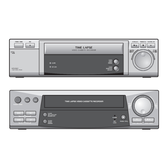
SECTION1 SUMMARY LOCATION OF CUSTOMER CONTROLS FRONT 1 POWER/TIMER BUTTON 2 MENU BUTTON 3 REC (RECORD) BUTTON 4 MOVE BUTTON 5 SEL (SELECT) BUTTON 6 DOWN BUTTON 7 UP BUTTON 8 ALARM INDICATOR 9 KEY LOCK INDICATOR REAR 1 POWER CORD 2 AUDIO IN/OUT JACK 3 VIDEO IN/OUT JACK 10 CASSETTE LOADING SLOT... - Page 5 SECTION1 SUMMARY LOCATION OF CUSTOMER CONTROLS INDICATOR PANEL 1 TIME LAPSE VCR TIME INDICATION 2 ALARM INDICATION 3 SERIES INDICATION 4 RECORD INDICATION 5 TIMER INDICATION 6 CASSETTE INDICATION VCR FUNCTION INDICATION 7 INDEX INDICATION 8 POWER FAILURE INDICATION 9 KEY LOCK INDICATION...
- Page 6 INPUT ‘Series Record’ work Output signal appears when the tape reaches to end or deck is OUTPUT error in recording. Outputs whether VCR deck is OUTPUT error. The signal is output which is used by switching several cameras in OUTPUT general space with using camera multi-plexer.
-
Page 7: Critical Parts Replacing Time Table
SECTION1 SUMMARY CRITICAL PARTS REPLACING TIME TABLE No. DESCRIPTION 1500 3000 5000 6000 7500 9000 10000 12000 Test freatures DRUM ASSY ARM ASSY CLEANER MOTOR CAPSTAN (D-35) BELT CAPSTAN BASE ASSY A/C HEAD F/E ARM ASSY IDLER HOLDER ASSY PINCH BAND ASSY TENSION 10 HOUSING ASSY 11 CAPSTAN SOFT BRAKE... -
Page 8: Cabinet & Main Frame
353-051A 353-051E 353-136A EXPLODED VIEWS DESCRIPTION SPECIFICATION ASSEMBLY SECTION DECK ASSEMBLY,VIDEO DECK/MECHA D35 LG T/L (4HD(ALL PWB(PCB) ASSEMBLY,TOTAL T/L VCR KEY2 JOG/SHUTTLE PANEL ASSEMBLY,FRONT CCD TIME LAPSE PANEL FRONT ASS PWB(PCB) ASSY,TOTAL TL-AR30 (SERIES) - W. RS232C - PWB(PCB) ASSEMBLY,TOTAL... - Page 9 SECTION2 CABINET & MAIN FRAME 1-1. Cabinet and Main Frame Section Cabinet & Main Frame Section Parts list ASSEMBLY PARTS SECTION 6871RK5700K Ass'y Front PCB 05503805 ASS'Y FRONT CAVINET 6871R-4462A Ass'y Ant. PCB 3501RK3200B Ass'y Main PCB EXPLODED VIEWS SNILN4T3526 NTH960 C-TYPE TL-AR30(SERIES) CCD LV-TL1960...
-
Page 10: Packing & Accessory Section
SECTION2 CABINET & MAIN FRAME 2. Packing & Accessory Section 803 : PACKING 804: SHEET ROLL 802: BOX CARTON • Packing Accessory Section Parts list MODEL : TL-AT130M S AL LOCA.NO. PART NO 3835RS0069N 3890R-C065K 3920R-E016A 3858R-S001A 534-008C 6711R1P041H EXPLODED VIEWS... -
Page 11: Electrical Adjustment Procedures
SECTION3 ELECTRICAL ELECTRICAL ADJUSTMENT PROCEDURES 1. PG ADJUSTMENT MODE SPECIFICATION PLAYBACK IN SP PG : 416 ± 20 1. Connect CH-1 of the oscilloscope to W357 and W362, and adjust it to 1Vp-p as TRIGGER. (In case of 10:1 Probe, adjust it 50m Vp-p) 2. -
Page 12: Electrical Troubleshooting Guide
SECTION3 ELECTRICAL ELECTRICAL TROUBLESHOOTING GUIDE 1. Power Circuit(SMPS) (1) No 5.3 A No 5.3V Is F101 normal? Is BD101 normal? Is R101 normal? Is there Vcc (about 13~19V) at IC101 pin 5? Is D106 normal? Is there about 2.5V at IC103 pin 1? Is D109 normal? Is L103 normal? - Page 13 SECTION3 ELECTRICAL ELECTRICAL TROUBLESHOOTING GUIDE (4) No 5.2 A (TO AVCP , BIAS) No 5.2V Is D106 normal? Is Q153 normal? Is there voltage (about 0V) at Q157 collector. Check/ Replace Q156 (5) No 10V No 10V Is D109 normal? Replace D106.
-
Page 14: Servo Circuit
SECTION3 ELECTRICAL ELECTRICAL TROUBLESHOOTING GUIDE 2. SERVO CIRCUIT (1) Video is unstable in PB mode In PB mode Does noise level on the screen change periodically? Does CTL pulse appear at IC501 Pin 76? Does CTL pulse move on tracking? Does Video Envelope wave form appear at IC501 pin 86? Replace IC501. - Page 15 SECTION3 ELECTRICAL ELECTRICAL TROUBLESHOOTING GUIDE (3) Capstan motor stops When the capstan motor stops Is it 12VA at PMC01 Pin2? Is there 2.8V at PMC01 Pin9? Check the Ass’y between PMC01 and Capstan motor Aren’t pattern or componets between IC501 Pin33 and PMC01 Pin9 short? Check CFG signal appear at IC501 Pin67? Does Capstan PWM signal appear...
-
Page 16: Y/C Circuit
SECTION3 ELECTRICAL ELECTRICAL TROUBLESHOOTING GUIDE 3. Y/C CIRCUIT (1) No Video in EE Mode No Video in EE Mode Does the Video signal appear at the IC3G1 Pin9? Does the Video signal appear at the IC301 Pin38? Is 5V applied to the IC301 Pin16, 40, 55, 58, 75, 87? Does the Video signal appear at the IC301 Pin29? - Page 17 SECTION3 ELECTRICAL ELECTRICAL TROUBLESHOOTING GUIDE (2) When the Y(Luminance)signal doesn’t appear on the screen in PB Mode. Is 5V applied to the IC301 Check the line of the 5.3VA Pin 16, 40, 55, 58, 87? Is the I C Bus signal applied Check the System Circuit.
- Page 18 SECTION3 ELECTRICAL ELECTRICAL TROUBLESHOOTING GUIDE (3) When the C(Color) signal doesn't appear on the screen in PB Mode Is 5V applied to the IC301 Pin 16, 40, 55, 58, 87? Is the Color Rotary signal applied to the IC301 Pin 10? Is Color Rotary "H"...
-
Page 19: Audio Circuit
SECTION3 ELECTRICAL ELECTRICAL TROUBLESHOOTING GUIDE 4. AUDIO CIRCUIT (1) No sound in EE Mode No sound in EE Mode. No sound. Is 5V applied to the IC301 Check the line of the 5V Line. Pin 75? Is the Audio signal applied to the IC301 Pin 76? Does the Audio signal appear Is the Audio Mute "High"... - Page 20 SECTION3 ELECTRICAL ELECTRICAL TROUBLESHOOTING GUIDE (3) No sound in REC Mode. NO sound in REC Mode. Sound is not recorded. Is Playback O.K.? Is the Audio signal applied Check the path of Line Audio. to the IC301 Pin 76? Is the “High” signal applied to the Does the Audio waveform appear at the IC301 Pin 7? Is 5V applied to the FL401...
-
Page 21: System/Key Circuit
SECTION3 ELECTRICAL ELECTRICAL TROUBLESHOOTING GUIDE 5. SYSTEM/KEY CIRCUIT (1) AUTO STOP Auto Stop Does SW waveform appear at IC501 Check Drum motor signal pin23? Does T/up reel pulse appear Does T/up reel pulse appear at IC501 Pin27? Replace T/up reel sensor of deck Replace IC501 (2) No cassette tape loading No cassette tape loading... -
Page 22: Osd Circuit
SECTION3 ELECTRICAL ELECTRICAL TROUBLESHOOTING GUIDE (3) No Key display No Key display Is there 5.2VA at IC501 Pin79, 80, 81? As pressing the byttons doeseach function work properly? 6. OSD CIRCUIT (1) No OSD display. No OSD display. Is there 5.3V IC501 Pin 51? Does oscillation appear at the IC501 PIns 37, 38? Check peripheral circuit and... -
Page 23: Block & Circuit Diagrams
SECTION3 ELECTRICAL BLOCK & CIRCUIT DIAGRAMS 1. OVERALL WIRING DIAGRAM 3-13 3-14... -
Page 24: Power Block Diagram
SECTION3 ELECTRICAL BLOCK & CIRCUIT DIAGRAMS 2. POWER BLOCK DIAGRAM 3-15 3-16... -
Page 25: Power Circuit Diagram
SECTION3 ELECTRICAL BLOCK & CIRCUIT DIAGRAMS 3. POWER CLRCUIT DIAGRAM 3-17 3-18... -
Page 26: Audio Block Diagram
SECTION3 ELECTRICAL BLOCK & CIRCUIT DIAGRAMS 4. AUDIO BLOCK DIAGRAM 3-19... -
Page 27: Y/C Block Diagram
SECTION3 ELECTRICAL BLOCK & CIRCUIT DIAGRAMS 5. Y/C BLOCK DIAGRAM 3-20... -
Page 28: A/V Circuit Diagram
SECTION3 ELECTRICAL BLOCK & CIRCUIT DIAGRAMS 6. A/V CIRCUIT DIAGRAM 3-21 3-22... - Page 29 SECTION3 ELECTRICAL BLOCK & CIRCUIT DIAGRAMS 3-23...
-
Page 30: System Block Diagram
SECTION3 ELECTRICAL BLOCK & CIRCUIT DIAGRAMS 7. SYSTEM BLOCK DIAGRAM 3-24 3-25... - Page 31 SECTION3 ELECTRICAL BLOCK & CIRCUIT DIAGRAMS 3-26...
-
Page 32: System Circuit Diagram
SECTION3 ELECTRICAL BLOCK & CIRCUIT DIAGRAMS 8. SYSTEM CLRCUIT DIAGRAM 3-27 3-28... -
Page 33: Jack Circuit Diagram
SECTION3 ELECTRICAL BLOCK & CIRCUIT DIAGRAMS 9. JACK CLRCUIT DIAGRAM 3-29 3-30... -
Page 34: Key-Board Circuit Diagram
SECTION3 ELECTRICAL BLOCK & CIRCUIT DIAGRAMS 10. KEY-BOARD CLRCUIT DIAGRAM 3-31 3-32... - Page 35 SECTION3 ELECTRICAL PRINTED CIRCUIT DIAGRAMS 1. MAIN P .C.BOARD 3-33 3-34...
-
Page 36: Printed Circuit Diagrams
SECTION3 ELECTRICAL PRINTED CIRCUIT DIAGRAMS 2. KEY 1 P .C.BOARD 3. KEY 2 P .C.BOARD PRINTED CIRCUIT BOARD DIAGRAMS 4. JACK P .C.BOARD 3-35... - Page 37 SECTION 4 MECHANISM DECK MECHANISM PARTS LOCATIONS • Top View...4-1 • Bottom View ...4-1 DECK MECHANISM DISASSEMBLY 1. Drum Assembly ...4-2 2. Plate Top ...4-4 3. Holder Assembly CST ...4-4 4. Opener Door ...4-4 5. Bracket Assembly L/D Motor...4-4 6. Gear Assembly Rack F/L ...4-4 7.
-
Page 38: Deck Mechanism Parts Locations
DECK MECHANISM PARTS LOCATIONS • Top View • Bottom View NOTE : When reassembly perform the procedure in the reverse order. 1) When reassembling, confirm Mechanism and Mode Switch Alignment Position (Refer to Page 4-13) 2) When disassembling, the Parts for Starting No. Should be removed first. -
Page 39: Deck Mechanism Disassembly
DECK MECHANISM DISASSEMBLY Carbon Brush 1. Drum Assembly (Fig. A-1-1) 1) Unplug the Drum FPC Connector. 2) Remove three Screws(S1) on bottom side and separate the Drum assembly. 3) Unhook (H1), (H2) and separate the Holder FPC and Cap FPC. 1-1. - Page 40 DECK MECHANISM DISASSEMBLY (Fig. A-2-1) Plate Top (B') (Fig. A-2-2) Holder Assembly CST (Fig. A-2-6) Arm Assembly F/L (C1) (Fig. A-2-7) Lever Assembly S/W (H8) Bracket Assembly L/D Motor Spring Lever S/W (Fig. A-2-4) (C') (E') Opener Door (Fig. A-2-3) (H6) Chassis Gear Assembly Rack F/L...
-
Page 41: Plate Top
DECK MECHANISM DISASSEMBLY 2. Plate Top (Fig. A-2-1) 1) Pull the (B) portion of the Plate Top back in direction of arrow and separate the right side of it. 2) pull the (B’) portion of the Plate Top back in direction of arrow and separate the left side of it. -
Page 42: Arm Assembly Cleaner
DECK MECHANISM DISASSEMBLY Head F/E (Fig. A-3-2) 9. Arm Assembly Cleaner (Fig. A-3-1) 1) Breakaway the (A) portion as Fig. A-3-1 from the embossing of the Chassis, turn the Arm assembly Cleaner to clockwise direction and lift it up. 10. Head F/E (Fig. A-3-2) 1) Breakaway the (A) portion of the Head F/E from the embossing of the Chassis, turn it to counterclockwise direction and lift it up. -
Page 43: Brake Assembly T
DECK MECHANISM DISASSEMBLY Arm Assembly Tension (Fig. A-4-3) (H11) Spring Tension (H12) Base Tension 12. Brake Assembly T (Fig. A-4-1) 1) Unhook the Spring TB from the Hook(H9) of the Chassis. 2) Lift the Brake Assembly T up. 13. Brake Assembly RS (Fig. A-4-2) 1) Unhook the Spring RS from the Hook(H10) of the Chassis. -
Page 44: Base Assembly P4
DECK MECHANISM DISASSEMBLY Base Assembly P4 (Fig. A-5-1) 16. Base Assembly P4 (Fig. A-5-1) 1) Breakaway the (A) portion of the Base Assembly P4 from the embossing of the Chassis. 2) Turn the Base Assembly P4 to counterclockwise direction and lift it up. 17. -
Page 45: Belt Capstan/Motor Capstan
DECK MECHANISM DISASSEMBLY Brake Assembly Capstan (Fig. A-6-5) (L2) (S5) 20. Belt Capstan (Fig. A-6-1)/ Motor Capstan (Fig. A-6-2) 1) Remove the Belt Capstan. 2) Remove the three Screws(S5) on bottom Chassis and lift the Motor Capstan up. 21. Lever F/R (Fig. A-6-3) 1) Unlock the Locking Tab(L1) as Fig. -
Page 46: Gear Drive/Gear Cam
DECK MECHANISM DISASSEMBLY Gear Cam Hole(B) Gear Drive Hole(A) Gear Drive Hole(C) 24. Gear Drive (Fig. A-7-1)/ Gear Cam (Fig. A-7-2) 1) Remove the Washer(W2) and lift the Gear Drive up. 2) Unhook the Hook(H14) of the Gear Cam and lift the Gear Cam up. -
Page 47: Gear Assembly P2
DECK MECHANISM DISASSEMBLY Gear Assembly P2 Hole Gear Assembly P3 Hole Lever Spring Boss 29. Gear Assembly P2 (Fig. A-8-1)/ Gear Assembly P3 (Fig. A-8-2) 1) Just lift the Gear Assembly P2 up. 2) Just lift the Gear Assembly P3 up. NOTE When reassembling, align the two holes of the Gear Assembly P2 and P3 in a straight line after confirmation... -
Page 48: Base Loading
DECK MECHANISM DISASSEMBLY Base Tension (Fig. A-9-2) 31. Base Loading (Fig. A-9-1) 1) Remove the Screw(S7). 2) Lift the Base Loading up. 32. Base Tension (Fig. A-9-2) 1) Breakaway the (A) portion of the Base Tension from the embossing of the Chassis. 2) Turn the Base Tension to counterclockwise direction and lift it up. -
Page 49: Deck Mechanism Adjustment
DECK MECHANISM ADJUSTMENT • Tools and Fixfures for Service 1. Cassette Torque Meter SRK-VHT-303(Not SVC part) Parts No: D00-D006 4. Torque Gauge Adaptor Parts No:D09-R001 2. Alignment Tape Parts No NTSC: DTN-001 PAL:DTN-0002 5. Post Height Adjusting Driver Parts No:DTL-0005 4-12 3. -
Page 50: Mechanism Alignment Position Check
DECK MECHANISM ADJUSTMENT 1. Mechanism Alignment Position Check Purpose:To determine if the Mechanism is in the correct position, when a Tape is ejected. Test Equipment/ Fixture • Blank tape 1) Turn the Power S/W on and eject the Cassette by press- ing the Eject Button. -
Page 51: Preparation For Adjustment
DECK MECHANISM ADJUSTMENT 2. Preparation for Adjustment (To set the Deck Mechanism of the loading state without inserting a cassette tape). 1) Unplug the power cord from the AC outlet. 2) Disassemble the Top Cover and Plate Assembly Top. 3) Plug the power cord into the AC outlet. 4) Turn the power S/W on and push the Lever Stopper of the Holder Assembly CST to the back for loading the 3. -
Page 52: Guide Roller Height Adjustment
If the adjustment is excessive or insufficient the tape will jam or fold. Test Conditions (Mechanism Condition) • Play or Review Mode ADJUSTMENT DIAGRAM Test Conditions VCR(VCP) State • Play an Alignment Tape PAL: SW 25Hz Waveform Diagrams P2 POST... -
Page 53: Audio/Control (A/C) Head Adjustment
DECK MECHANISM ADJUSTMENT 5. Audio/Control (A/C) Head Adjustment Purpose: To insure that the tape passes accurately over the Audio and Control Tracks in exact alignment of the both Record and Playback Modes. 5-1. Preliminary Adjustment (Height and Tilt Adjustment) Perform the Preliminary Adjustment, when there is no Audio Output Signal with the Alignment Tape. Test Equipment/ Fixture •... -
Page 54: Precise Adjustment(Azimuth Adjustment)
Tilt Adjustment Screw(C) for maximum output of the 1KHz and 7KHz segments, while maintaining the flattest envelope differential between the two frequencies. 6. X-Value Adjustment Purpose: To obtain compatibility with the other VCR(VCP) Models. Test Equipment/ Fixture • Oscilloscope • CH-1: PB RF Envelope •... -
Page 55: Adjustment After Replacing Drum Assembly (Video Heads)
CH1 CH2 Fig. C-7 Test Conditions (Mechanism Condition) • Play an Alignment Tape (with 6H 3kHz Color Bar Signal) Test Conditions (Mechanism Condition) VCR(VCP) State • Run the CUE, REV, Play mode at the beginning and the end of the tape. -
Page 56: Maintenance/Inspection Procedure
MAINTENANCE/INSPECTION PROCEDURE 1. Check before starting repairs The following faults can be remedied by cleaning and oil- ing. Check the needed lubrication and the conditions of cleanliness in the unit. Check with the customer to find out how often the unit is used, and then determine that the unit is ready for inspec- tion and maintenance. -
Page 57: Required Maintenance
MAINTENANCE/INSPECTION PROCEDURE 2. Required Maintenance The recording density of a VCR(VCP) is much higher than that of an audio tape recorder. VCR(VCP) components must be very precise, at tolerances of 1/1000mm, to ensure com- patibility with the other VCRs. If any of these components are worn or dirty, the symptoms will be the same as if the part is defective. -
Page 58: Greasing
MAINTENANCE/INSPECTION PROCEDURE 5-2) Greasing (1) Greasing guidelines Apply grease, with a cleaning patch. Do not use exces- sive grease. It may come into contact with the tape transport or drive system. Wipe excessive grease and clean with cleaning patch wetted in Isopropyl Alcohol. NOTE:Greasing Points 1) Loading Path Inside &... - Page 59 MAINTENANCE/INSPECTION PROCEDURE Lever, F/R, Base, Tension Lever, F/R Clutch (G-754. Yellow) GEAR AY, P2 & P3 Base, Tension Arm Tension Guide Hole 4-22 Boss...
-
Page 60: Mechanism Troubleshooting Guide
MECHANISM TROUBLESHOOTING GUIDE 1.Deck Mechanism Auto REW doesn't work. Is the output of END sensor of supply side "H"? “H”: more than 3.5V “L”: less than 0.7V~1V Is the voltage across IR LED between 0.8~1.5V? Check the syscon circuit. No F/R modes. Is the present mode F/R Mode? Does the Capstan Motor rotate? - Page 61 MECHANISM TROUBLESHOOTING GUIDE AUTO STOP. (PLAY/CUE/REV) In Play/Cue/Rev, Is the Pinch Roller in contact with the Capstan Shaft? Are there T/up and Supply Reel pulses. Check the Syscon, µ-COM. Cassette doesn’t load. Insert the cassette. Does the Lever Assembly S/W work normally? Is there variation for CST IN S/W Output?
- Page 62 MECHANISM TROUBLESHOOTING GUIDE In PB mode Tape Presence not sensed. Is the Pinch Roller attached to the Capstan Motor Shaft? Does the T/Up Reel turn? Does the Capstan Motor turn? Does the Drum Motor turn? Are there DPG, DFG pulses? Are the T/Up and Supply Reel Sensors ok? Check the Servo, Syscon.
-
Page 63: Front Loading Mechanism
MECHANISM TROUBLESHOOTING GUIDE 2. Front Loading Mechanism Cassette cannot be inserted. Does the Lever Assembly Switch work? Is the Vcc of Main P.C.Board Is the voltage between cassette switch and GND on Main P.C.Board 5V?? Check the Mode switch location and syscon circuit. - Page 64 MECHANISM TROUBLESHOOTING GUIDE Cassette does not load. Does the cassette insert? Does the Opener Lid work? Does the Gear Assembly Rack F/L work? Does the Opener Door work? Does the Arm Assembly F/L work? Does the L/D Motor work? Does the Holder Assembly Cassette move the Arm Assembly F/L? Replace the Front Loading Mechanism Assembly.
-
Page 65: Exploded Views
EXPLODED VIEWS 1. Front Loading Mechanism Section 4-28... -
Page 66: Moving Mechanism Section (1)
EXPLODED VIEWS 2. Moving Mechanism Section(1) OPTIONAL PART 4-29... -
Page 67: Moving Mechanism Section (2)
EXPLODED VIEWS 3. Moving Mechanism Section(2) OPTIONAL PART 4-30... - Page 68 NTH960N...
- Page 69 NTH960 K5700K 05503807 3211RKS008B FRAME ASSEMBLY 3501RK3200B BOARD ASSEMBLY 0502527 50502166 190B C/SKD SNILN4T3526 NTH960 C-TYPE VCR MAIN(S008B) + PACKING CCD TL-AT230 HRV30C NTH960C LCD PWB(ABS XR-401)
- Page 70 NTH960...
- Page 71 N H960...
- Page 72 NTH960...
- Page 73 NTH960...
- Page 74 NTH960 RUN DATE : 2004.05.01...
- Page 75 NTH960...
- Page 77 NTH960...
- Page 78 NTH960...
- Page 80 NTH960...